
Development of an Autonomous Flying Excavator †


Department of Automotive and Mechatronics Engineering, Ontario Tech University, Oshawa, ON L1G 0C5, Canada
*
Author to whom correspondence should be addressed.
†
Presented at the 1st International Electronic Conference on Machines and Applications, 15–30 September 2022; Available online: https://iecma2022.sciforum.net/ .
Eng. Proc. 2022, 24(1), 4; https://doi.org/10.3390/IECMA2022-12909
Published: 21 September 2022
(This article belongs to the Proceedings of The 1st International Electronic Conference on Machines and Applications)
Abstract
:In the construction industry, excavation is a difficult task that needs to be automated to save on resources such as cost, time, and labor. In this paper, a prototype of an excavating drone is presented which can operate totally autonomously without human interaction. The navigation control is achieved with Pixhawk flight controller and ARDUPILOT Mission Planner is used for path planning. A drone platform is integrated with an excavating arm that can exert 42 N of force to dig and lift the soil. A sensing algorithm is also developed by using the 3D depth camera integrated into the platform for a fully autonomous operation.
1. Introduction
The construction industry is one of the most focused industrial sectors that require autonomous technology to operate in harsh environments and excavation is the key stage of any construction process. For this task, an excavator is an indispensable tool that can handle duties that other machines cannot. By realizing the innovative idea that excavations can be carried out using a drone platform, many construction sites can speed up the related work in any environmental conditions and expand their working areas to any height levels using drones. In this study, an autonomous flying excavator platform is proposed in which a 3D printed excavator assembly is mounted on the drone. The platform ensures to withstand all the counter forces during the excavation in flight mode. The flight of the drone is autonomous using the prescribed mission uploaded on the controller. A Pixhawk cube orange is used with the latest Here 3 GPS and RTK technology to achieve accurate position control in the air. For the detection of soil piles, a sensing algorithm is developed under ROS architecture which uses 3D point cloud mapping techniques to properly place the tip of the bucket for excavation. The whole focus of this study is to give an idea of an autonomous flying excavator which can be very effective and beneficial in the construction industry from a different perspective. Section 2 provides a literature review on existing aerial manipulators and uses of drones in different construction applications. In Section 3, the working methodology is presented, and the sensing algorithm is in Section 4. Experimental results are given in Section 5 and finally, in the last section, concluding remarks and future works are presented.
2. Literature Review
Several different types of aerial manipulators have been used in the past. Some of these devices address sensor placement, gripping items in the air, and exerting force on various objects. In [1], a 2 DOF manipulator with a revolute joint and a prismatic joint for sensor placement was utilized to overcome this challenge. To make sure that none of the assembly pieces was close to the motors or their blades [2], a cable was used in tethered drones to connect the drone platform to the manipulator. In this way, it is possible to control all the components of the drone from the ground, where the battery status can be monitored, and the base station laptop can receive data about the drone’s real-time position so that it can send the correct coordinates to the controller for position control. In [3], a cable-suspended load was lifted from the ground by an unmanned aerial robot when the load mass was unknown. However, strong external forces cannot be applied to these systems since the drone may become unstable. Various types of airborne platforms were discussed in [4] to deal with the challenges of gripping an object, securing a sensor, and applying some force to a surface to execute the required duties. Dual manipulators were employed to handle any object that a single manipulator could grasp. These dual manipulators help provide extra rigidity to any parts, sensors, or platforms in architecture. However, there has been no method of attaching the manipulator to the drone for excavating activities, which encouraged us to create an excavator drone platform that would be a very innovative contribution to the construction and drone industries.
In recent years, drones have been widely used in many different construction activities, which mainly include building and land surveys, topographical mapping, and inspection of construction sites. A small drone has been utilized to eliminate safety risks associated with roof surveying and to gain access to difficult or complex roof sections [5]. The creation of topographic maps can be expensive and time-consuming, but they are of great value for all construction projects. In this situation, drones are an appropriate solution since they are capable of collecting a vast amount of data in a short period of time and thus can save costs, time, and other resources [6]. In [7], the support system’s geometry was captured using a smartphone-controlled multirotor drone during the excavation phase. Then, the 2D imaging data were converted into 3D construction staging models to obtain a detailed record of construction activities, including the site geometry change and geotechnical engineering evaluation, which can help builders to take future steps in the projects more effectively. The use of drones in the construction industry is limited to mapping, surveying, and image collection only. This motivated us to devise an idea for a flying excavator prototype that can utilize drones extensively for autonomous excavation.
3. Working Methodology
The proposed excavating drone platform has a three-component structure. First, we have the F450 mm frame size drone equipped with an orange cube Pixhawk controller and the Here 3 GPS system that is responsible for the drone’s flight, stability under diverse load situations, and maneuverability with robust control. The open-source Ardupilot platform was used to configure the Pixhawk controller, allowing various sensor modules, such as the IMU, magnetometer, and internal GPS data, to be utilized for the smooth operation of the flight. The second part is the manipulator which was first designed using the CAD tool Solid works 2018. Each part was 3D printed and after assembling all the components, they were rigidly fixed with the drone using nuts and bolts. The platform design process ensured that none of the components would contact the drone’s blades during flight and excavation operations. Especially, the interference of manipulator components with the blades was carefully cross-checked through the CAD model and simulations to prevent it before final assembly. The stability of the platform was also taken into account in the design process. In the initial design, all three components of the excavator boom, arm, and bucket were assembled. However, this design caused an instability issue, i.e., whenever the manipulator operated in flight mode, its center of mass shifted significantly, making the platform unbalanced and fall over. To resolve the above issue, the actuator and link for the boom were eliminated, leaving only two actuators for the arm and bucket. As a result, the total length of the manipulator was shortened from 410 mm to 374 mm.
This design change allowed us to balance the platform by moving the center of gravity to the lower center of the platform. Using inverse kinematics equations, the controller determines the length of each actuator and then sends the suitable amount of PWM signals for positioning the bucket’s tip at the correct location. The third component is the sensing algorithm which uses depth to detect the excavated ground and generate its 3D point cloud map. A cropping technique was employed to filter out unnecessary points and only the points within the region of interest (i.e., the area of excavated ground) are transmitted to the controller for processing, which then commands the excavator to begin excavation from the correct location.
3.1. Path Planning and Control
For successful drone navigation, it is a prerequisite to calibrate the radio transmitter and the motor ESCs through the mission planning platform that allows them to communicate with each other. To control the drone’s pitch, yaw, roll, and throttle, the transmitter was configured by adjusting the flying modes and channel and model settings. It is important to make sure that the “Failsafe” feature is always on during the drone flight so that it can return and land in the same spot where it first took off when flying out of the transmitter’s range. The flight modes used in this study are Loiter, Auto, and Autotune, which are available on the Ardupilot mission planner platform. The PID control parameters for the copter were fine-tuned using Autotune prior to the experiment in which the copter executed yaw, pitch, and roll movements. At the beginning of the experiment, the copter was armed in the Loiter mode, which can lock the GPS position, and after being given a small amount of throttle, it switched to the Auto mode to carry out the mission entirely autonomously. The EMAX 2826 motors and a Hobby King 70-amp ESC were utilized with 10 inches diameter propellers with two rotating in the clockwise direction and two in the anticlockwise direction [8]. Autonomous navigation control was achieved using GPS, RTK, and a mission planner. The user-given location was converted into longitude and latitude coordinates for the GPS module mounted on the drone using the mission planner. Positional accuracy can be enhanced up to a centimeter level using the RTK system. Then, the drone can precisely follow the coordinates and land at a target location for excavation. Autonomous navigation is terminated when the sensor begins scanning soil piles and it is resumed to dump the excavated soil to the designated area.
3.2. Excavator Modeling and Working Principles
The assembly of the excavator was designed using SOLIDWORKS 2018 and 3D-printed with PLA material. We chose the PLA because it can be printed quickly and withstand the required digging force during excavation. Figure 1 shows the CAD model for the components that require 3D printing.
The Atuonix L12 I series actuators with a gearing choice of 1:100 were employed in our platform. In full retraction and extension, their lengths are 102 mm and 152 mm, respectively. Each actuator weighs about 40 g and can handle a load of 42 N. The actuators can be actuated by sending PWM signals to Arduino which was selected as a microcontroller in this study. Figure 2 and Figure 3 show the platform created after assembling all the required hardware components.
4. Sensing Algorithm
For the fully autonomous excavation with the prototype platform, a sensing algorithm was developed by using the Intel Real sense D415 depth camera. This algorithm was used to detect the surface of the excavated soil with sensing data. Moreover, the sensing information can be used for the controller to generate the required commands to execute excavating operations and stabilize the drone. For the autonomous operation, we used the Nvidia Jetson Nano as an onboard computer, and the software architecture was based on the ROS platform. The packages utilized in our application are Intel real sense depth camera, pcl ros, move it, and mavros. As shown in Figure 4, the Intel real sense camera and PCL ROS package allow us to detect the terrain and publish point cloud information that can be visualized in RVIZ. After sensing the ground surface, the filtering technique (i.e., cropping point cloud) was applied to reduce the number of points along the x and z axes that do not belong to the region of interest (area of excavated ground).
5. Experimentation
To validate the performance of the developed platform, the test scenario was considered as seen in Figure 5, which outlined each step-by-step moment during one cycle of autonomous excavation. The drone took off from the initial home position and then landed at the targeted location. Based on the processed sensory information about the target ground for excavation, the platform started digging and loading the soil into the bucket. Then, the drone flew again to dump the soil in the prescribed area and finally landed at the original location after completing the required mission. The entire operation, position accuracy, and stability of the drone need to be guaranteed. For position control, RTK system data were fused with the GPS to get the most accurate location information. For stability, all the ESCs were finely tuned to deliver the appropriate amount of PWM signals to each motor. During the experiment, the platform navigated along the trajectory shown in Figure 6. The developed platform successfully completed autonomous excavation by handling the position accuracy and stability in the given scenario. The used RTK system and GPS provide centimeter-level positional accuracy for the platform. In the experiment, the target landing point and actual landing point for excavation were (0.000, 3.000) m and (0.004, 2.992) m, respectively. During the flight to reach this target point, the RMSE value between the desired trajectory (blue line in Figure 6) and the actual flight path (red line) was 0.00894 m. After that, the platform completed the dumping process in the air and landed at the final destination, whose desired and landed points were (1.500, 2.992) m and (1.492, 2.995) m. Finally, the RMSE value between the desired trajectory (green line) and the actual path (black line) to the final destination was 0.00854 m. Table 1 provides a summary of these results. For stability, the maximum lean angle allowable for the loiter mode in which the excavation was conducted was 30 degrees, and the average lean angle of our copter during the entire experiment was 20 degrees. Therefore, a stable flight was maintained during the operation.
6. Conclusions
The construction industry is one of the fields where drones are in use for various purposes to save time and costs. In this paper, a flying excavator prototype was presented using a drone equipped with the Pixhawk controller and Ardupilot mission planner interface. In addition, a sensing algorithm was developed to detect the excavated ground at the construction site. By using the detected ground information, the developed flying excavator platform was able to conduct the required digging task autonomously in the considered test scenario. To improve the control of the drone during excavation, a high-precision 1D LiDAR can be added to the platform for accurate height control. In addition, a more advanced GPS technology or flight mode control could be considered to lock the lateral and longitudinal directions of the platform, which is effective for maintaining the drone’s position under dynamic weather conditions such as wind.
Author Contributions
Writing—original draft preparation, A.M.Z.; writing—review and editing, J.S. All authors have read and agreed to the published version of the manuscript.
Funding
The research was funded by The Natural Sciences and Engineering Research Council of Canada (RGPIN-2020-05663).
Institutional Review Board Statement
Not applicable.
Informed Consent Statement
Not applicable.
Data Availability Statement
Not applicable.
Conflicts of Interest
The authors declare no conflict of interest.
References
- Lee, H.-J.; Liu, H.-C.; Jeong, G.; Lee, J. Newly proposed hybrid type multi-DOF operation motor for multi-copter UAV systems. In Proceedings of the 2016 IEEE Conference on Electromagnetic Field Computation (CEFC), Miami, FL, USA, 13–16 November 2016; p. 1. [Google Scholar] [CrossRef]
- Kim, D.; Oh, P.Y. Toward Lab Automation Drones for Micro-plate Delivery in High Throughput Systems. In Proceedings of the 2018 International Conference on Unmanned Aircraft Systems (ICUAS), Dallas, TX, USA, 12–15 June 2018; pp. 279–284. [Google Scholar] [CrossRef]
- Cruz, P.; Fierro, R. Autonomous lift of a cable-suspended load by an unmanned aerial robot by an unmanned aerial robot. In Proceedings of the 2014 IEEE Conference on Control Applications (CCA), Antibes, France, 8–10 October 2014; pp. 802–807. [Google Scholar] [CrossRef]
- Ruggiero, F.; Trujillo, M.A.; Cano, R.; Ascorbe, H.; Viguria, A.; Peréz, C.; Lippiello, V.; Ollero, A.; Siciliano, B. A multilayer control for multirotor UAVs equipped with a servo robot arm. In Proceedings of the 2015 IEEE International Conference on Robotics and Automation (ICRA), Seattle, WA, USA, 26–30 May 2015; pp. 4014–4020. [Google Scholar] [CrossRef]
- Parisi, F.; Mangini, A.M.; Fanti, M.P.; Parisi, N. A Drone-Assisted 3D Printing by Crane Structures in Construction Industry. In Proceedings of the IEEE 17th International Conference on Automation Science and Engineering (CASE), Lyon, France, 23–27 August 2021; pp. 171–176. [Google Scholar] [CrossRef]
- Tasevski, S. The Use of Drones on Commercial Construction Projects. Available online: https://dronebelow.com/2018/11/01/the-use-of-drones-on-commerical-construction-projects/ (accessed on 20 September 2022).
- Li, Y.; Liu, C. Applications of multirotor drone technologies in construction management. Int. J. Constr. Manag. 2019, 19, 401–412. [Google Scholar] [CrossRef]
- GT2826. Emax. 2022. Available online: https://emaxmodel.com/products/gt2826 (accessed on 13 August 2022).
Figure 1.
SolidWorks CAD model of drone components.
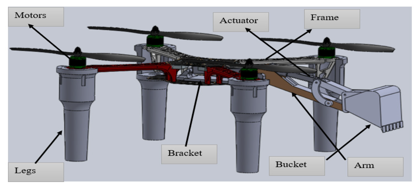
Figure 2.
Top view of the assembled point platform.

Figure 3.
Isometric view of the assembled platform.

Figure 4.
Sensing of the cloud data.

Figure 5.
The yellow circle highlights the drone in each figure. Drone taking off from the initial point (a), drone en route to be landed landmark (b), drone landmark doing excavation autonomously (c), dumping the excavated soil (d), and the drone arrived back after the excavation operation (e).
Figure 5.
The yellow circle highlights the drone in each figure. Drone taking off from the initial point (a), drone en route to be landed landmark (b), drone landmark doing excavation autonomously (c), dumping the excavated soil (d), and the drone arrived back after the excavation operation (e).

Figure 6.
Navigation trajectory of the platform experiment.


Table 1.
Experiment results.
| For excavation | Desired Landing Position | Actual Position | For Dumping | Desired Landing Position | Actual Position |
| (0.000, 3.000) m | (0.004, 2.992) m | (1.500, 2.992) m | (1.492, 2.995) m | ||
| Root Mean Square Error (RMSE): 0.00894 m | Root Mean Square Error (RMSE): 0.00854 m | ||||
Publisher’s Note: MDPI stays neutral with regard to jurisdictional claims in published maps and institutional affiliations. |
© 2022 by the authors. Licensee MDPI, Basel, Switzerland. This article is an open access article distributed under the terms and conditions of the Creative Commons Attribution (CC BY) license (https://creativecommons.org/licenses/by/4.0/).
Share and Cite
MDPI and ACS Style
Zaman, A.M.; Seo, J. Development of an Autonomous Flying Excavator. Eng. Proc. 2022, 24, 4. https://doi.org/10.3390/IECMA2022-12909
AMA Style
Zaman AM, Seo J. Development of an Autonomous Flying Excavator. Engineering Proceedings. 2022; 24(1):4. https://doi.org/10.3390/IECMA2022-12909
Chicago/Turabian StyleZaman, Arif Mehmood, and Jaho Seo. 2022. "Development of an Autonomous Flying Excavator" Engineering Proceedings 24, no. 1: 4. https://doi.org/10.3390/IECMA2022-12909