Proceeding Paper

Refractive Index Sensing in a Disposable Micro-Channel Provided with Integrated Reflectors Based on Laser Beam Shift †

Department of Electrical, Computer and Biomedical Engineering, University of Pavia, 27100 Pavia, Italy
*
Author to whom correspondence should be addressed.
Presented at the 9th International Electronic Conference on Sensors and Applications, 1–15 November 2022; Available online: https://ecsa-9.sciforum.net/.
Eng. Proc. 2022, 27(1), 49; https://doi.org/10.3390/ecsa-9-13195
Published: 1 November 2022

Abstract

:
In this work, we present a compact micro-opto-fluidic sensing platform for the measurement of volumetric refractive index (RI) variations of ultra-low volumes of fluids with respect to a reference liquid. In the instrumental configuration, we employed a disposable plastic micro-channel, which was customized with integrated back and front aluminum reflectors, deposited by sputtering. The presence of the double metallization is exploited to create a zigzag guiding path for the radiation provided by a semiconductor laser diode, so that light crosses the fluid under test multiple times before reaching a 1-D Position Sensitive Detector (PSD). According to Snell law, when fluids with different RI indices fill the channel, the radiation is deflected at different angles and the output beam shifts along the channel surface. RI variations are monitored by measuring the position of the output light spot on the surface of the PSD. To validate the results, a theoretical model based on ray optics was developed to study the propagation of the radiation travelling through the fluidic channel. Experimental results showed a beam displacement per RI unit up to 3234 μm/RIU, in agreement with the prediction of the analytical model. The proposed sensing method is label-free, contactless, non-invasive, and biologically safe. Moreover, the micro-opto-fluidic sensing platform could be exploited in a wide range of applications, ranging from biology to medicine to the agri-food industry.

1. Introduction

Sensors based on refractive index (RI) detection exploit the fact that many physical quantities, such as concentration and temperature, determine a change in the sample RI as a consequence. Therefore, RI measurements can be exploited in a wide range of applications such as in disease diagnosis [1,2], chemical and biological sensing [3,4], and the food and beverage industry [5,6,7].
The main requirement of the new-generation devices for the analysis of fluids is the possibility to perform a contactless and non-invasive measurement. This requirement can be satisfied by optical sensors, that present several advantages in terms of size, cost of fabrication, robustness, and sensitivity.
There are different optical methods for measuring the RI of liquids. For example, fiber-optics sensors are widely used, but they must be placed in contact with the fluid under test; thus, they are not suitable for contactless sensing. RI changes can also be detected by exploiting Surface Plasmon Resonance (SPR) sensors, although such systems require expensive components and complex fabrication and preparation.
Consequently, nowadays, there is still an urgent need to develop low-cost sensing platforms based on innovative optical techniques to analyze fluids in a totally non-invasive way. Towards this aim, several authors proposed techniques based on the change of direction of a refracted laser beam [8,9,10,11]. Basically, when a laser beam impinges obliquely on a rectangular cell filled with liquid and passes through the cell, the propagation axis of the transmitted beam is shifted from that of the incident beam. By measuring the displacement, it is possible to determine the refractive index of the liquid [11].
In this work, we present a compact micro-opto-fluidic sensing platform for the measurement of volumetric RI variations of ultra-low volumes of fluids based on a similar detection method. We used a disposable plastic microslide, which was customized with integrated back and front aluminum reflectors so that the radiation provided by a semiconductor laser diode can be zigzag-guided into the channel, crossing the fluid under test multiple times before reaching the active surface of a 1-D Position Sensitive Detector (PSD). RI variations are monitored by measuring the position of the output light spot on the surface of the PSD. The working principle of the sensor was demonstrated by testing glucose–water solutions. To validate the results, a theoretical model based on ray optics was developed to study the propagation of the radiation travelling through the fluidic channel.

2. Materials and Methods

2.1. Optoelectronic Instrumental Configuration

The instrumental configuration for the contactless sensing of fluids is shown in Figure 1. The red radiation provided by a semiconductor laser diode (DL3147-060, Sanyo, Japan) is shone on a disposable plastic micro-channel at an angle of approximately 45° and it is focused using a lens (LTN330B, Thorlabs, NJ, USA) to obtain the smallest light spot onto the active surface of a 1-D Silicon Position Sensitive Detector. The PSD (1L10SU74-SPC02, by SiTek Electro Optics AB, Partille, Sweden) is powered with a ±15 V voltage supply and provides two output voltage signals: the difference signal V1V2 and the sum signal V1 + V2. The V1 and V2 are proportional to the currents that are photogenerated at the extremities of the sensitive region that has length LPSD = 10 mm. The light spot position pPSD on the PSD, with respect to the center of the sensitive area, can be retrieved by computing the formula:
pPSD = (LPSD/2)∙(V1V2)/(V1 + V2)
The output signals supplied by the PSD are visualized in real time and acquired with an oscilloscope. Data are further processed in a MATLAB environment.
The micro-fluidic device investigated in this work is a polymer channel microslide (IBIDI μ -Slide I0.8 LUER by IBIDI GmbH, Gräfelfing, Germany) with a nominal channel depth of 800 μm and connection tubings that allow the easy injection and ejection of the fluids by means of a syringe. It is realized in a bio-compatible material and allows the contactless remote analysis of ultra-low volumes of a sample. The bottom layer of the microslide is coated for its entire length with a 50-nm-thick aluminum (Al) layer, while the top layer presents a 5-mm-long Al layer (Lmet = 5 mm). These metallizations, deposited by sputtering, act as mirrors, inducing zigzag light propagation through the structure. In this way, incident light crosses the fluid multiple times, thus increasing the sensitivity of the measurement.

2.2. Theoretical Model

A theoretical model based on ray optics was developed in a MATLAB environment to study the light propagation through the microslide to obtain analytical results that could be compared with the results of the experiments. The model predicts the displacement of the output beam position onto the surface of the PSD when the channel is filled with samples with different RIs. It was developed by considering the microslide as a multi-layer structure composed of three layers with finite thicknesses (nominal value of the front polymer layer thickness tf = 180 μm, nominal value of the channel thickness d = 800 μm, and back polymer layer thickness tb ≈ 1 mm), immersed in air (the RI of air is taken equal to 1). No tolerance is reported by the manufacturer for the channel depth and wall thickness, but it is reasonable to suppose that the microslide’s actual dimensions could slightly differ from the nominal ones. Hence, for the microfluidic device, a deviation of ±10% on the parameter d was considered and the theoretical study was carried out for d = 720, 800, and 880 μm. The refractive index of the polymeric layers was considered equal to 1.52 RIU, as reported on the device datasheet. When light crosses the separation surface between media with different RIs, it is partially reflected and partially transmitted according to Snell’s law. The total pathlength inside the microslide can be calculated by recursively applying Snell’s formula. The geometrical distance p between the entrance and exit positions of the light beam in the microslide depends on the RI of the sample tested.
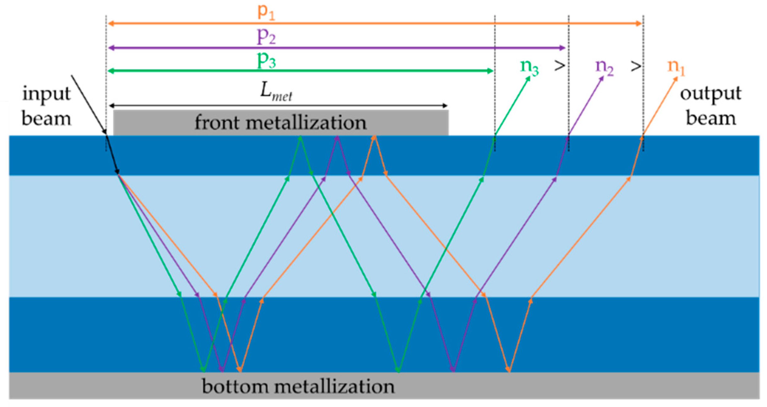
When fluids with different RIs are tested, the light beam always exits the channel with the same output angle (that is equal to the incidence angle), but its exit position along the fluidic device surface does change. For increasing values of the RI, it is moved closer to the incident input beam and the value of p decreases, as shown in Figure 2, where a schematic representation of light traveling inside the channel in case of a number of bounces equal to N = 2 is reported. If the orange, purple, and green lines correspond to the paths of light when the channel is filled with a sample with an RI equal to n1, n2, and n3, respectively, and n3 > n2 > n1, then p3 < p2 < p1. The number of bounces N depends on the length of the front metallization Lmet and it is given by:
N = CEIL(Lmet/p)
where CEIL is the MATLAB function that returns the smallest integer value that is larger than or equal to Lmet/p. The model can also be used to predict the exact length of the front metallization, after the number of bounces has been chosen, simply inverting Equation (2).
The theoretical displacement Xth of the light beam exiting the capillary was obtained by computing the difference between p obtained with a sample fluid (psample) and water (pwater), that was taken as a reference fluid:
Xth = |psamplepwater|

3. Results and Discussion

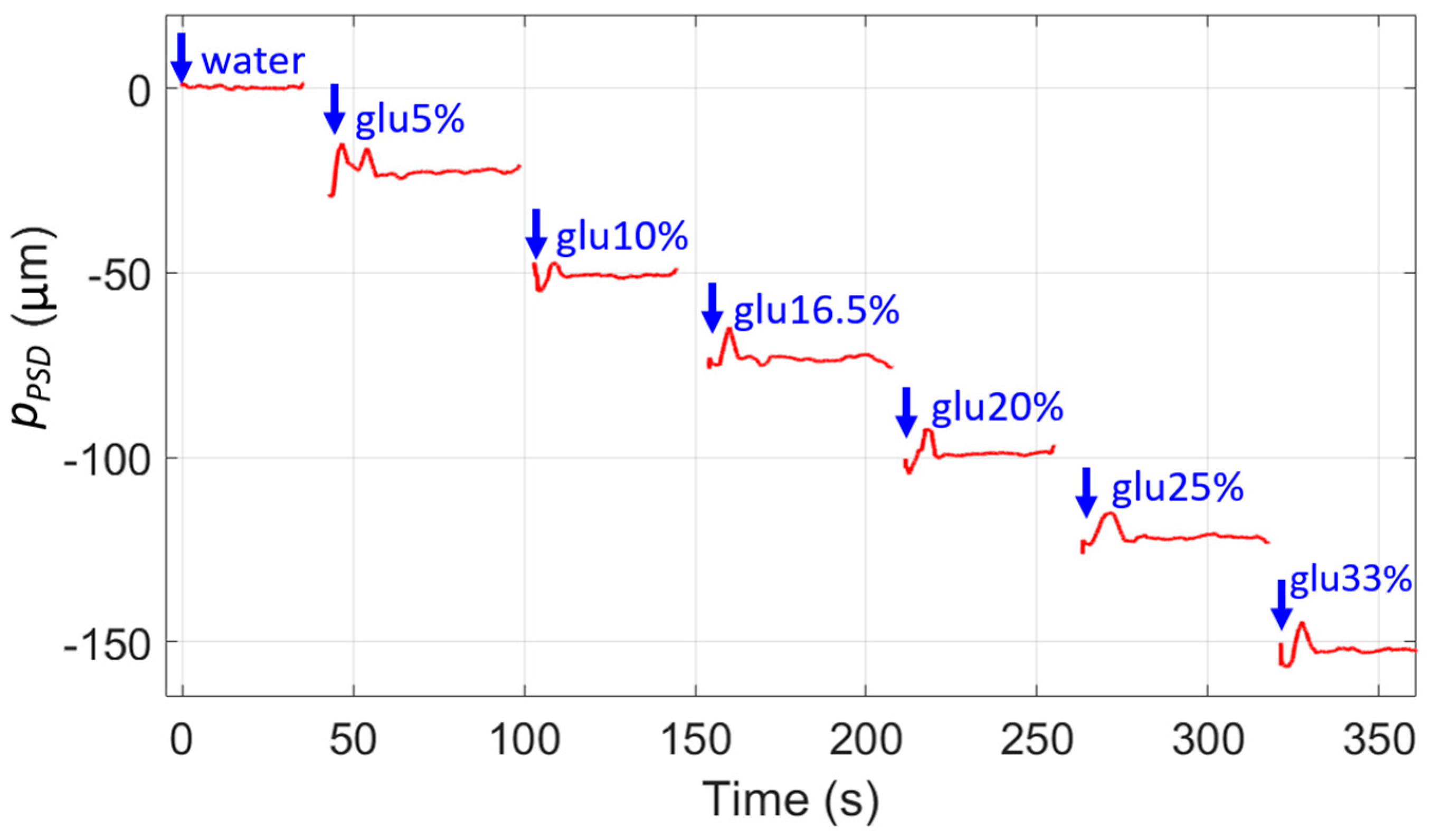
Experimental measurements were carried out in the so-called “multiple bounce configuration”. Thanks to the presence of the double metallization, the displacement of the output beam can be strongly enhanced. The number of bounces N was estimated to be equal to 3 using Equation (2). For the experimental characterization, the channel was filled with distilled water and mixtures of glucose in water in concentrations equal to 0%, 5%, 10%, 16.5%, 20%, 25%, and 33%, corresponding to RI values n = 1.3314, 1.3386, 1.3459, 1.3553, 1.3604, 1.3676, and 1.3792 RIU, respectively. Figure 3 shows the experimental variation of the beam position pPSD detected by the PSD as a function of time when water and water–glucose solutions with different concentrations are tested. The system was aligned so that the reflected beam in the presence of water into the channel reaches approximately the center of the active area of the PSD (i.e., pPSD equal to zero). When the RI of the liquid inserted into the channel increases, the absolute value of the displacement increases as well, with respect to the value of the signal acquired in the presence of water.
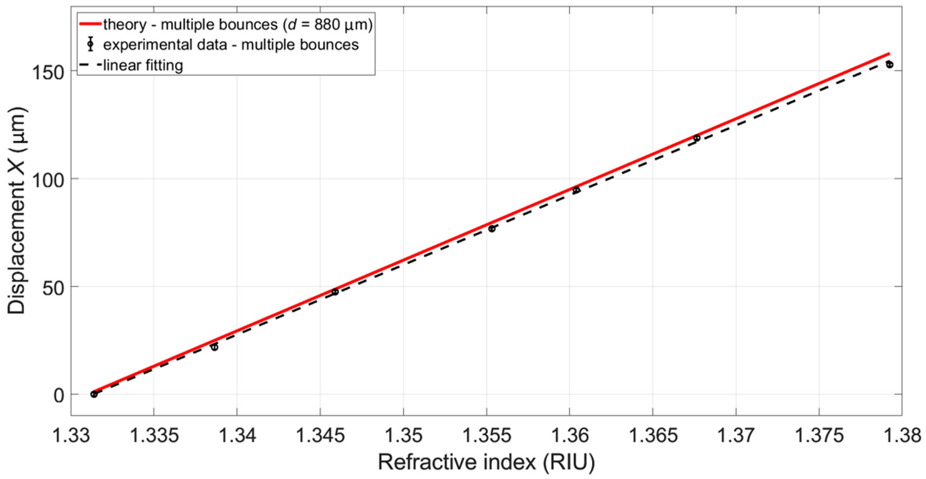
By linearly fitting the theoretical and experimental displacement X as a function of the liquid RI, it was possible to obtain both theoretical (red trace) and experimental (black trace) calibration curves (Figure 4), that were found to be in extremely good agreement. The theoretical displacement Xth is given by Equation (3), whereas the experimental displacement Xesperim of the light beam position with respect to that measured when water (chosen as a reference fluid) flows into the channel was recovered as follows:
Xexperim = |pPSD_FLUIDpPSD_WATER|
where pPSD_FLUID and pPSD_WATER are the positions of the light spot on the PSD obtained when the fluid sample and water flow into the channel, respectively. The largest displacement X of the laser spot was obtained for the sample with the highest RI. We reported the theoretical calibration curve that is in best agreement with the experimental one, obtained by considering d = 880 μm. The sensitivity depends on d and on the number of bounces N: the higher the number of bounces N and channel depth d, the longer the distance p. Exploiting the zigzag-guided effect due to the presence of the double metallization of the microslide, it was possible to obtain an experimental beam displacement per RI unit up to 3234 μm/RIU.

4. Conclusions

In this work, we proved the functionality of an optical method to distinguish fluids based on their RI in a non-invasive and contactless way. When the RI changes, the output beam position shifts along the channel surface: the operating principle of the sensors is based on the measurement of the light spot displacement onto the active surface of a PSD with respect to a reference fluid. The working principle and the potentiality of the micro-fluidic platform were demonstrated by filling the channel with distilled water and mixtures of glucose in water in concentrations up to 33%. The experimental results were found to be in very good agreement with the prediction of the analytical model. The multiple bounce configuration (with N = 3 estimated by the model) has allowed to achieve a beam displacement per RI unit up to 3234 μm/RIU. The deposition of Al thin layers is a simple and low-cost technology that allows the fabrication of a smart device with high sensitivity, suitable for several biomedical and chemical applications.

Author Contributions

Conceptualization, E.B. and V.B.; methodology, V.B.; software, E.B. and V.B.; validation, E.B. and V.B.; formal analysis, E.B. and V.B.; investigation, E.B. and V.B.; data curation, E.B. and V.B.; writing—original draft preparation, E.B.; writing—review and editing, V.B.; visualization, E.B. and V.B.; supervision, V.B.; project administration, V.B. All authors have read and agreed to the published version of the manuscript.

Funding

This research was partially funded by the Regional Operational Program of the European Regional Development Fund-POR FESR 2014-2020 program through the project “DSF (Digital Smart Fluidics): Fluidica Digitale per le Scienze della Vita”, grant number 1175234.

Institutional Review Board Statement

Not applicable.

Informed Consent Statement

Not applicable.

Data Availability Statement

Not applicable.

Acknowledgments

The authors express their gratitude to Sabina Merlo of the Department of Electrical, Computer and Biomedical Engineering of the University of Pavia for her guidance and fruitful suggestions. The authors wish to thank F. Tessicini and A. Bratto, Fluid-oTech, Corsico, Italy, and F. Auricchio and R. Romarowski, DICAr, University of Pavia, Pavia, Italy, for fruitful discussions. The authors thank F. Nicollini too, for technical support in the measurements.

Conflicts of Interest

The authors declare no conflict of interest.

References

  1. Liu, P.Y.; Chin, L.K.; Ser, W.; Chen, H.F.; Hsieh, C.-M.; Lee, C.-H.; Sung, K.-B.; Ayi, T.C.; Yap, P.H.; Liedberg, B.; et al. Cell refractive index for cell biology and disease diagnosis: Past, present and future. Lab Chip 2016, 16, 634–644. [Google Scholar] [CrossRef]
  2. Seyyedmasoumian, S.; Attariabad, A.; Pourziad, A.; Bemani, M. refractive index biosensor using metamaterial perfect absorber based on graphene in near-infrared for disease diagnosis. IEEE Sens. J. 2022, 22, 14870–14877. [Google Scholar] [CrossRef]
  3. Eid, M.; Habib, M.; Anower, M.; Rashed, A.N.Z. Highly sensitive nonlinear photonic crystal fiber based sensor for chemical sensing applications. Microsyst. Technol. 2021, 27, 1007–1014. [Google Scholar] [CrossRef]
  4. Alizadeh, S.; Zareian-Jahromi, E.; Mashayekhi, V. A tunable graphene-based refractive index sensor for THz bio-sensing applications. Opt. Quantum Electron. 2022, 54, 73. [Google Scholar] [CrossRef]
  5. Shin, H.J.; Choi, S.W.; Ok, G. Qualitative identification of food materials by complex refractive index mapping in the terahertz range. Food Chem. 2018, 245, 282–288. [Google Scholar] [CrossRef] [PubMed]
  6. Belay, A.; Assefa, G. Concentration, wavelength and temperature dependent refractive index of sugar solutions and methods of determination contents of sugar in soft drink beverages using laser lights. J. Lasers Opt. Photonics 2018, 5, 1000187. [Google Scholar]
  7. Seki, A.; Narita, K.; Watanabe, K. Refractive index measurement in sucrose solution and beverage using surface plasmon resonance sensor based on hetero-core structured fiber optic. Procedia Chem. 2016, 20, 115–117. [Google Scholar] [CrossRef] [Green Version]
  8. Chao, K.S.; Lin, T.Y.; Yang, R.J. Two optofluidic devices for the refractive index measurement of small volume of fluids. Microfluid. Nanofluidics 2012, 12, 697–704. [Google Scholar] [CrossRef]
  9. Jääskeläinen, A.; Silvennoinen, R.; Peiponen, K.E.; Räty, J. On measurement of complex refractive index of liquids by diffractive element-based sensor. Opt. Commun. 2000, 178, 53–57. [Google Scholar] [CrossRef]
  10. Jiménez, F.; Vázquez, J.; Sánchez-Rojas, J.L.; Barrajón, N.; Úbeda, J. Multi-purpose optoelectronic instrument for monitoring the alcoholic fermentation of wine. In Proceedings of the SENSORS, Limerick, Ireland, 28–31 October 2011. [Google Scholar]
  11. Nemoto, S. Measurement of the refractive index of liquid using laser beam displacement. Appl. Opt. 1992, 31, 6690–6694. [Google Scholar] [CrossRef] [PubMed]
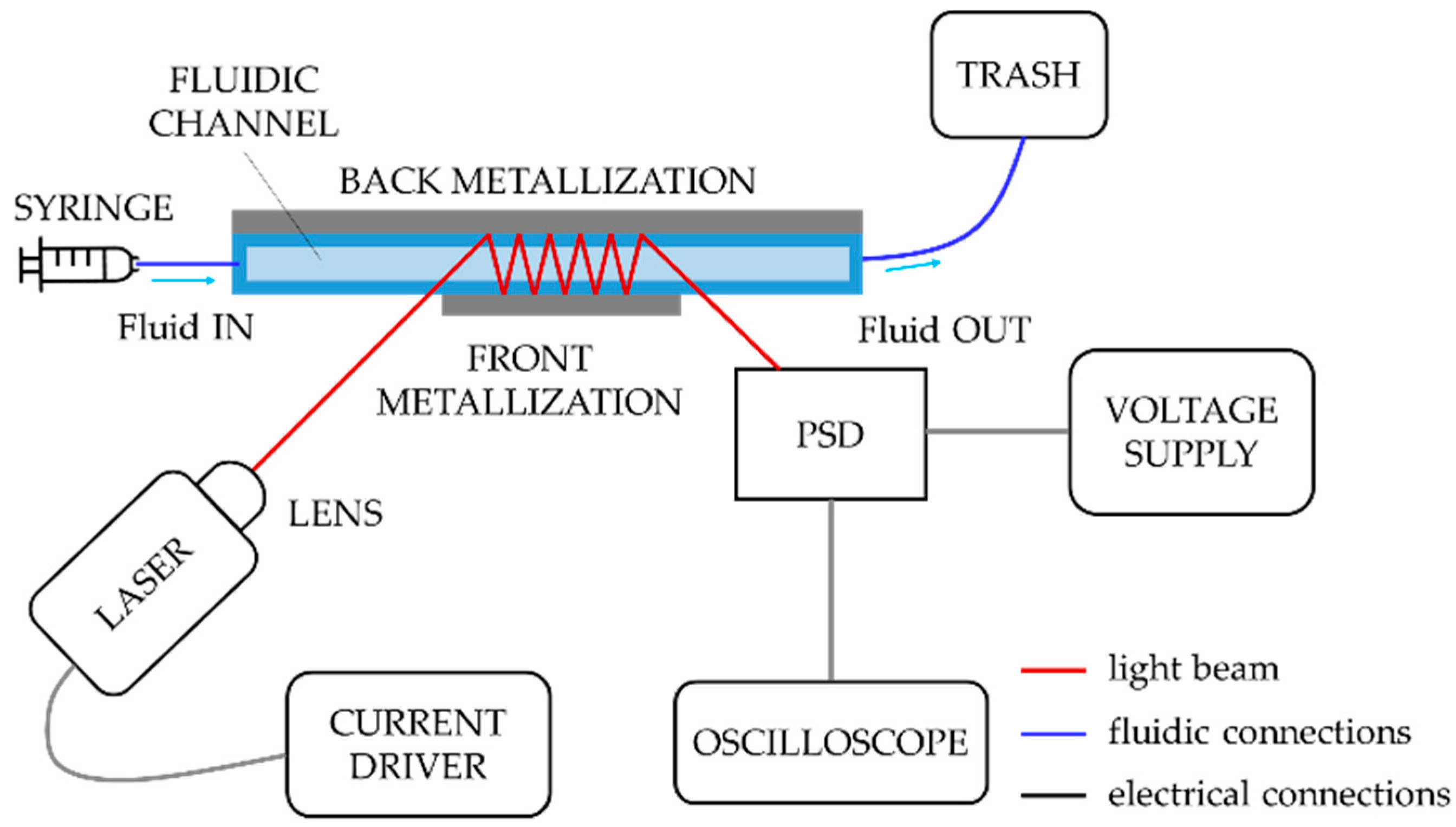
Figure 1. Schematic representation of the instrumental configuration for optical detection.
Engproc 27 00049 g001
Figure 2. Schematic representation of the propagation of the light into the channel when different sample fluids with increasing RI are considered (N = 2).
Engproc 27 00049 g002
Figure 3. Variation of the beam position pPSD detected by the PSD as a function of time when water and water–glucose solutions with different concentrations are tested.
Engproc 27 00049 g003
Figure 4. Theoretical and experimental calibration curves obtained by considering water and glucose–water solutions filling the channel.
Engproc 27 00049 g004
Publisher’s Note: MDPI stays neutral with regard to jurisdictional claims in published maps and institutional affiliations.