Abstract
Sonic-IR, which detects defects based on the temperature rise due to frictional heating at the defect faces under ultrasonic excitation, has an advantage in the detection of closed defects. However, in the conventional sonic-IR method, an acoustic energy is directly input from an ultrasonic transducer to the test object via an ultrasonic horn, which may give some scratches and deformation to the test object. To avoid such a problem, we have developed a new sonic-IR method using an ultrasonic wave input via water, and the practicability of the proposed method for the detection of fatigue crack has been experimentally demonstrated. This study presents the results of an investigation of the effect of immersion conditions on heat generation at defects in the proposed method.
1. Introduction
Sonic-IR, which is also called vibro-thermography, is one of the active thermographic NDT techniques. This method, which is based on the detection of the temperature rise due to frictional heating at the defect faces under ultrasonic excitation, has an advantage in the detection of closed defects. The method was originally developed by Henneke [1] in 1979 and has been advanced and improved more recently. However, in the conventional sonic-IR method, an acoustic energy is directly input from an ultrasonic transducer to the test area via an ultrasonic horn, which may give scratches and deformation in the test object.
To avoid such a problem, we have developed a new sonic-IR method using an ultrasonic wave input via water [2]. The proposed method does not cause surface scratches or deformation in the inspected object, which is a concern with the conventional direct excitation method. Moreover, by immersing several parts in the ultrasound bath for testing, it is expected that they can be inspected in a shorter time. The authors have experimentally demonstrated the practicality of the proposed method for fatigue crack detection [2]. However, the proposed method generates relatively less heat at the defects than the conventional method, and it is considered necessary to improve the accuracy of defect detection.
In this study, as a basic study to improve the accuracy of defect detection, we experimentally investigate the effects of water level in the ultrasonic bath on the sound pressure in the water and the heat generated at the defects.
2. Defect Detection by Immersion Sonic-IR Method
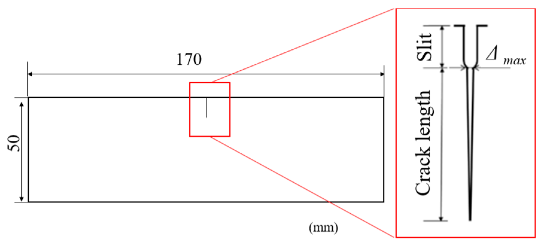
Specimens with a one-sided through-crack are used in the experiments, as shown in Figure 1. The specimen material was carbon steel, JIS SS400. A 5 mm slit was introduced into a plate by electrical discharge machining, and a crack was initiated and propagated to approximately 22 mm in length from the tip of the slit by a four-point bending fatigue test. Then, the plate was sliced to produce specimens with thicknesses of 0.5 mm and 6 mm.
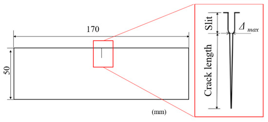
Figure 1.
Shape and dimensions of the specimen.
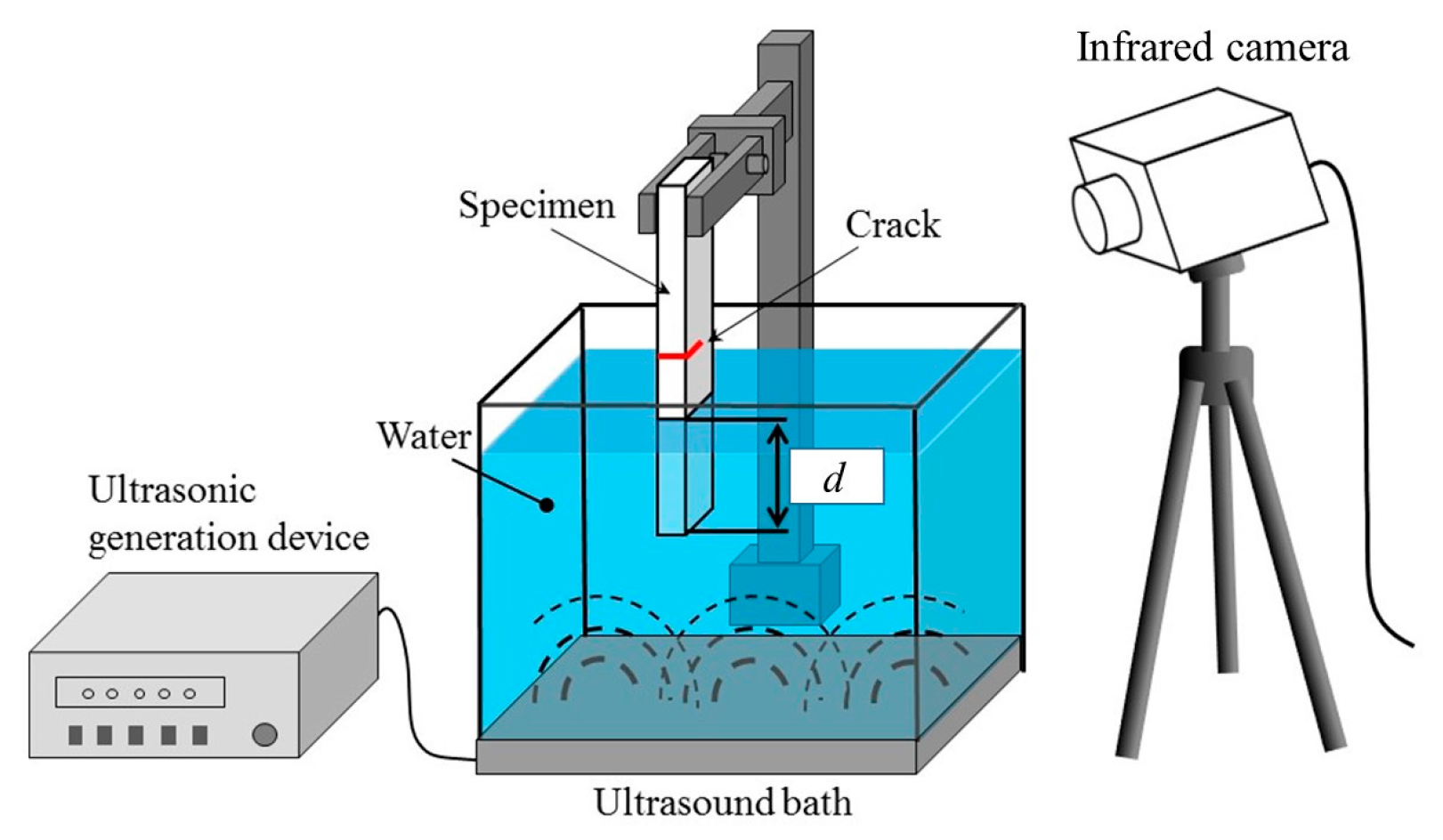
The sonic-IR system used in this study is shown in Figure 2. An ultrasound bath, model VS-600IIIS (VELVO-CLEAR), was used to generate the acoustic energy. The maximum ultrasonic excitation power was 600 W, and the ultrasonic frequency was set to 45 kHz. The dimensions of the bath were 325 mm in length, 275 mm in width, and 250 mm in height. Water was employed as the liquid of the ultrasound bath. A part of the specimen was immersed in water, and ultrasonic waves were input to the specimen via water.
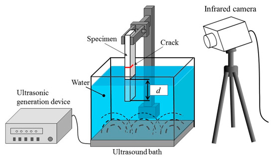
Figure 2.
Schematic illustration of the sonic-IR method using the ultrasound bath.
Heat generation around the crack during ultrasonic excitation was measured. For temperature measurement, the high performance infrared camera (FLIR systems JAPAN, Tokyo, Japan) with InSb infrared sensors (temperature resolution: 25 mK, spectral range: 3.0–5.0 μm, spatial resolution: 320 × 256 pixels) was employed. Infrared measurement frequency was set to 113 Hz. Flat black paint for emissivity improvement was applied on the surface of the specimen.
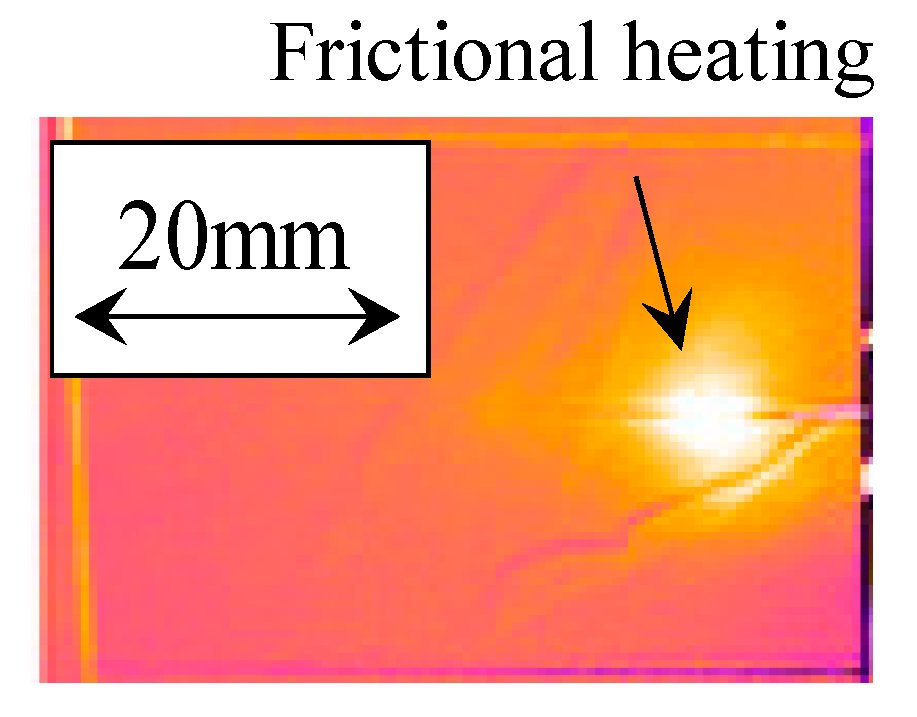
Figure 3 shows an example of the heat generated around a crack during ultrasonic excitation of a specimen, as captured by an infrared thermography camera. The white areas indicated by the arrows in the figure are areas of increased temperature due to frictional heating generated in the crack zone by ultrasonic excitation.

Figure 3.
An example of the infrared image of the heat generation at a fatigue crack caused by the sonic-IR test.
3. Effect of Water Level and Specimen Immersion Depth on Heat Generation at Defects
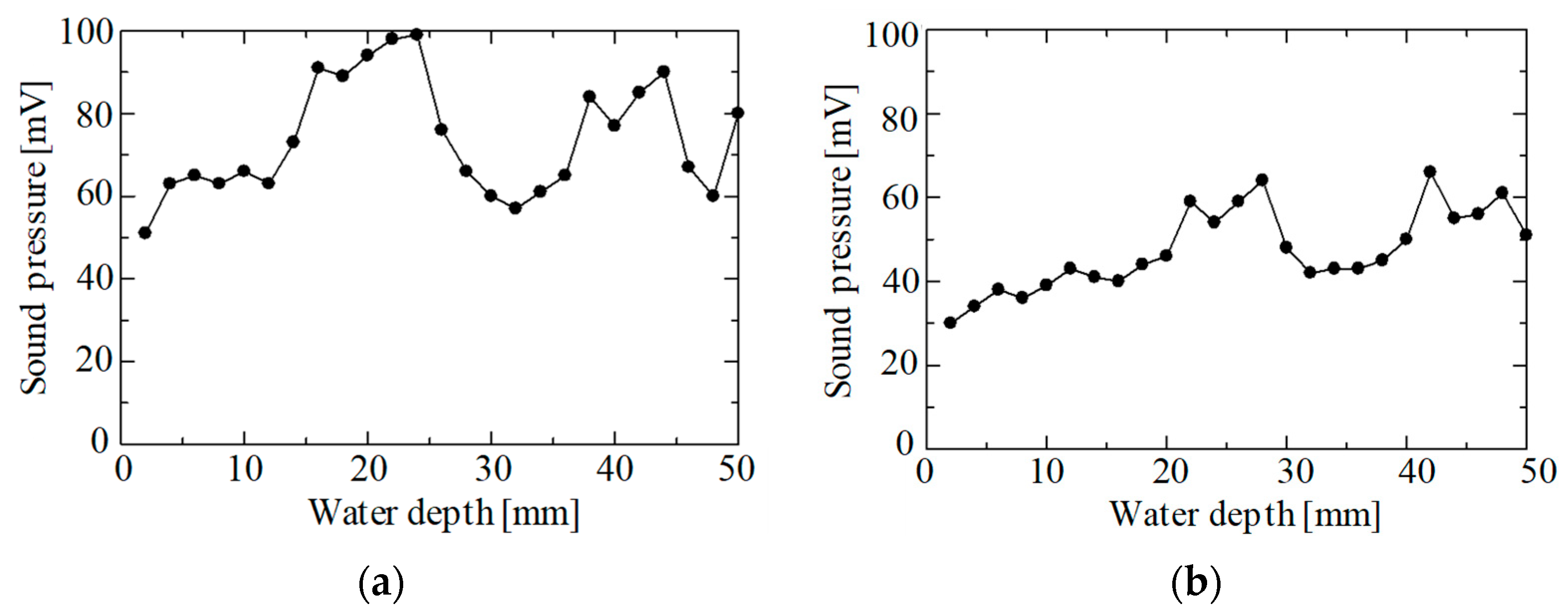
The relationship between water depth and ultrasonic sound pressure was measured at several different water levels. Figure 4 shows the relationship between water depth and sound pressure at water levels of 170 mm and 200 mm. Due to the standing waves in the water, several peaks were observed in the relationship between water depth and sound pressure. Figure 5 shows the average sound pressure from the surface to a depth of 50 mm at each water level. The average sound pressure level changed depending on the water level.
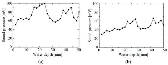
Figure 4.
The relationship between water depth and ultrasonic sound pressure: (a) water level is 170 mm; (b) water level is 200 mm.
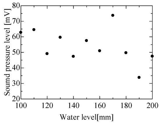
Figure 5.
Relationship between water level and average sound pressure.
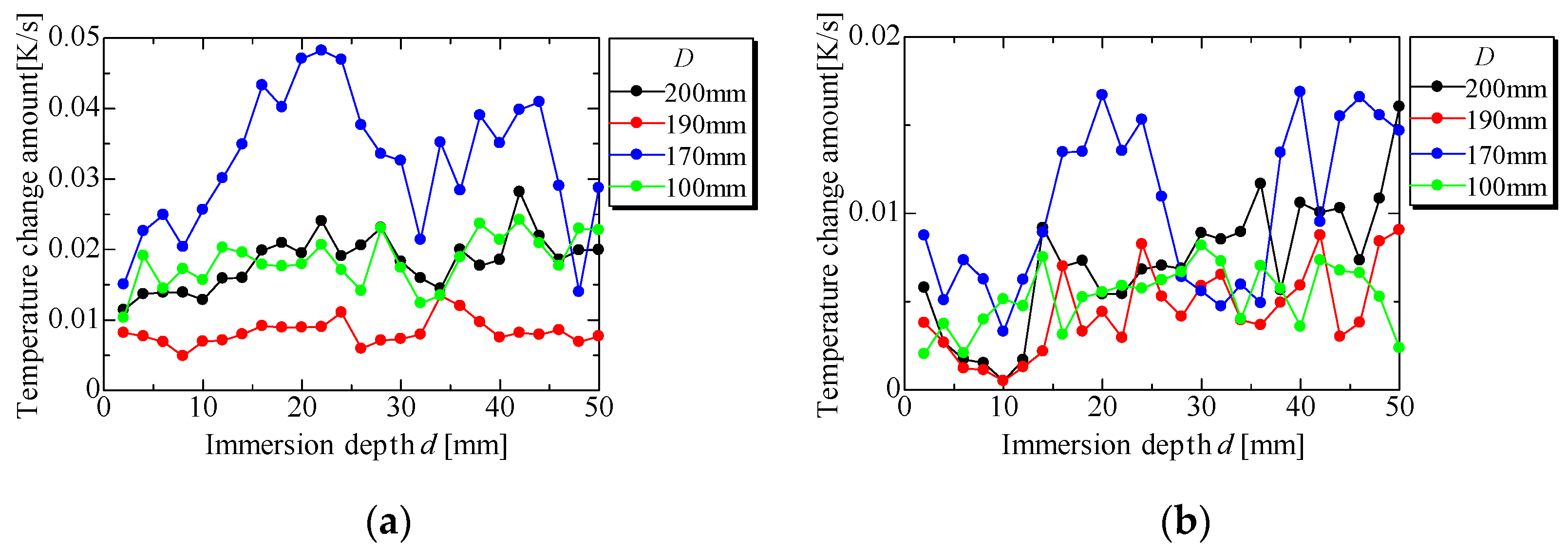
Figure 6 shows the relationship between the immersion depth of the specimen and the temperature change around the crack, obtained with a thickness of 0.5 mm and 6 mm, respectively. Several peaks appear in the relationship between the immersion depth of the specimen and the temperature change around the crack. In addition, as shown in Figure 5, when the water level D was 170 mm, which had a high average sound pressure, the heat generation around the crack increased.
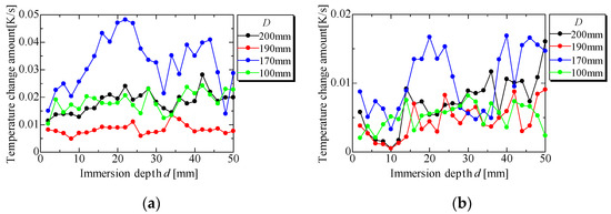
Figure 6.
Relationship between immersion depth of specimen and temperature change around crack: (a) 0.5 mm thickness; (b) 6 mm thickness.
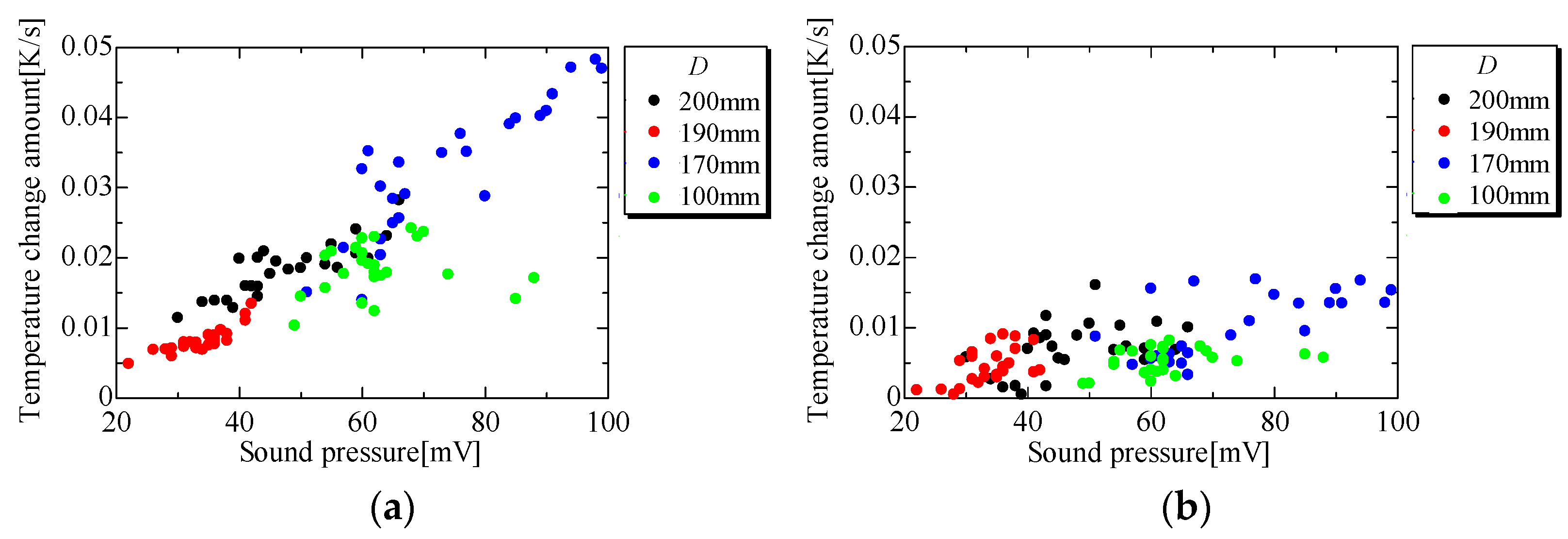
Figure 7 shows the relationship between the temperature change around the crack and the sound pressure of water at the bottom of the specimen. A positive correlation was observed between heat generation and sound pressure at the bottom of the specimen. The ultrasonic input to the specimen is applied from all sides of the flooded area of the specimen. Figure 7 indicates that the heat generation at the crack is strongly influenced by the ultrasonic input, especially from the bottom of the specimen.
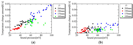
Figure 7.
Relationship between temperature change around crack and sound pressure of water at the bottom of the specimen: (a) 0.5 mm thickness; (b) 6 mm thickness.
In general, the edge of an object is often the free edge and the belly of the natural vibration. Studies using the direct excitation sonic-IR method [3] have shown that ultrasonic excitation with a horn at the belly of the natural vibration in a specimen causes significant natural vibrations, resulting in higher heat generation at the crack. In this experiment, the bottom of the specimen was the belly of the natural vibration, and when the sound pressure of the water near the bottom of the specimen was high, the specimen showed significant natural vibration and the heat generation at the crack was also large.
4. Conclusions
At water levels with high mean sound pressure, significant heat generation was observed around the cracks. This experiment also showed that the sound pressure of the water at the bottom of the specimen had a significant effect on the heat generation at the cracks. In the future, we would like to clarify the effects of ultrasonic oscillation conditions and immersion conditions on the vibration behavior of the test object and to clarify the mechanism of heat generation in the defects of the proposed method.
Author Contributions
Conceptualization, Y.I., H.T., S.K. and N.K.; methodology, Y.I., H.T., S.K. and N.K.; software, Y.I., S.K. and N.K.; formal analysis, Y.I., H.T., S.K. and N.K.; investigation, Y.I., H.T., S.K. and N.K.; resources, Y.I., H.T., S.K. and N.K.; data curation, Y.I., H.T., S.K. and N.K.; writing—original draft preparation, Y.I.; writing—review and editing, Y.I., H.T., S.K. and N.K.; visualization, Y.I., H.T., S.K. and N.K.; supervision, Y.I. and H.T.; project administration, Y.I. and H.T.; funding acquisition, Y.I. and H.T. All authors have read and agreed to the published version of the manuscript.
Funding
This research was funded by a Grant-in-Aid for Young Scientists (B) grant number 17K14561 from the Japan Society for the Promotion of Science.
Institutional Review Board Statement
Not applicable.
Informed Consent Statement
Not applicable.
Data Availability Statement
The data are not publicly available.
Conflicts of Interest
The authors declare no conflicts of interest.
References
- Henneke, E.G., II; Reifsnider, K.L.; Stinchcomb, W.W. Thermography—An NDI Method for Damage Detection. J. Metal. 1979, 31, 11–15. [Google Scholar] [CrossRef]
- Izumi, Y.; Tanabe, H.; Hibino, T.; Takamatsu, T.; Sakagami, T. Development of new sonic-IR method using ultrasonic wave inputted through water. In Proceedings of the 13th International Workshop on Advanced Infrared Technology & Application, Pisa, Italy, 29 September–2 October 2015; pp. 275–278. [Google Scholar]
- Tanabe, H.; Izumi, Y.; Akimichi, Y. Relationship between Heat Generation at Single Edge Penetration Crack in Strip Specimen and Vibrational Modes of Specimen in Sonic-IR Method. J. Soc. Mater. Sci. Jpn. 2020, 69, 902–909. [Google Scholar] [CrossRef]

Disclaimer/Publisher’s Note: The statements, opinions and data contained in all publications are solely those of the individual author(s) and contributor(s) and not of MDPI and/or the editor(s). MDPI and/or the editor(s) disclaim responsibility for any injury to people or property resulting from any ideas, methods, instructions or products referred to in the content. |
© 2024 by the authors. Licensee MDPI, Basel, Switzerland. This article is an open access article distributed under the terms and conditions of the Creative Commons Attribution (CC BY) license (https://creativecommons.org/licenses/by/4.0/).