Proceeding Paper

Effect of Tool Rotational Speed and Dwell Time on the Joint Strength of Friction Stir Spot Welded AA6061-T6 Sheets †

Department of Civil and Materials Engineering, University of Malaga, 29071 Malaga, Spain
*
Author to whom correspondence should be addressed.
Presented at the 4th International Electronic Conference on Applied Sciences, 27 October–10 November 2023; Available online: https://asec2023.sciforum.net/.
Eng. Proc. 2023, 56(1), 215; https://doi.org/10.3390/ASEC2023-15229
Published: 26 October 2023
(This article belongs to the Proceedings of The 4th International Electronic Conference on Applied Sciences)

Abstract

:
Friction stir spot welding (FSSW) is a technique employed to join materials in the solid state. It was first employed by the companies Mazda and Kawasaki as a novel sub-technique of friction stir welding to alternate the spot resistance welding. FSSW successively joined both similar and dissimilar metals. Tool rotational speed and dwell time are the most effective FSSW process parameters. This study investigated the role of the rotational speed of the tool and the dwell time in determining the FSSW joints’ strength using AA6061-T6 aluminum alloy sheets with a thickness of 1.8 mm as a work piece material. A classic milling machine was employed to carry out the welding process. Four different values of the rotational speed of tools with two dwell time values were taken to fabricate the FSSW joints. Four joints were made for each FSSW process condition. Three joints were averaged to determine the tensile–shear fracture load. The other specimen was employed to examine the micro-Vickers hardness and the microstructure. The investigation reported an increase in the joint strength within a certain range of tool rotational speeds and dwell time values corresponding to grain refinement in the weld zone. The variation in mechanical properties was attributed to the corresponding frictional heat generation and material flow during the welding process. Strain hardening and dynamic recrystallization determined the weld nugget hardness. Lower mechanical properties were observed with the excessive heat generation and flow of material with very high speeds and dwell time values.

1. Introduction

Recently, there has been a growing need for the use of lightweight metal alternatives in transportation industries, aircrafts, aerospace industry, various structural components, and many other industrial applications due to the high costs of fossil hydrocarbon fuels as well as to reduce their environmental impact. Friction stir spot welding (FSSW) is a solid-state welding technique that has been successfully employed to join lightweight metals, such as aluminum, magnesium, titanium, zinc, etc. [1]. Figure 1 represents the process of the FSSW and shows its procedures: (1) plunging, (2) stirring and (3) retracting. Plunging includes inserting a rotating welding tool that has a pin and shoulder into the work piece to a specific depth. During the FSSW process, the joint is formed under the effect of frictional heat generation, induced material flow and the applied forging force. The tool is then retracted leaving a feature called “Keyhole”. The joint is formed depending on the frictional heat generation and material flow under the forging force of the welding tool [1]. Several process parameters mainly affect the FSSW joint characteristics, such as tool rotational speed, dwell time, plunge rate and plunge depth [2]. These parameters play a dominant role in determining the weld quality and failure modes. The rotational speed of a tool is a dominant welding parameter that controls the weld strength followed by dwell time. The dwell time value should not exceed a specified range to prevent the formation of weak joints [3]. Heat generation in the weld is proportional to the dwell time because it allows more friction between the tool pin and shoulder with the work pieces being friction stir welded. Shen et al. [4] studied the effects of the tool rotation speed and the dwell time on the mechanical properties of the FSSW weld joints and concluded that the tensile shear load increased with the tool rotation speed and dwell time, and the tool rotation speed played a very important role in determining the strength [4,5]. Sathyaseelan et al. [6] investigated how dwell time influences the fracture load of dissimilar metals. They reported that the optimal frictional heat input could improve the FSSW joint strength, and the recrystallization of grains and the distribution of intermetallic compound control the weld quality. Rojikin et al. [7] observed a decrease in the tensile strength with an increase in tool rotational speed of more than 1600 rpm, and this result was related to an increase in the thickness of the intermetallic compounds. Ugla et al. [8] reported that the tensile strength was linearly related to the tool rotational speed and decreased over a certain range of dwell time because of the excessive heat input in the weld region. The FSSW weld microstructure consists of four distinct neighboring zones symmetric with respect to the Keyhole, namely stir zone (SZ), thermomechanically affected zone (TMAZ), heat affected zone (HAZ) and base metal zone (BM). These zones differ in morphology depending on their influence by the frictional heat and the material flow during the welding process, which mainly depend on the tool rotational speed and the dwell time [4,6,7,8].
The heat-treatable AA6061-T6 aluminum alloy is one of the most commonly used alloys in different industrial applications such as truck frames, motorboats, ship building and aerospace applications. It has a good weldability and a good strength/weight value [1].
Previous studies have investigated the FSSW with specific welding conditions, process parameters, and materials and come up with their corresponding findings. However, more research is required for the inclusion of various combinations of welding process parameters for many metals and alloys of industrial and research importance.
This study will focus on investigating two of the most influential parameters of the FSSW process of AA6061-T6 alloy, and the results will contribute to raising the economic and design feasibility of its various industrial applications.

2. Materials and Methods

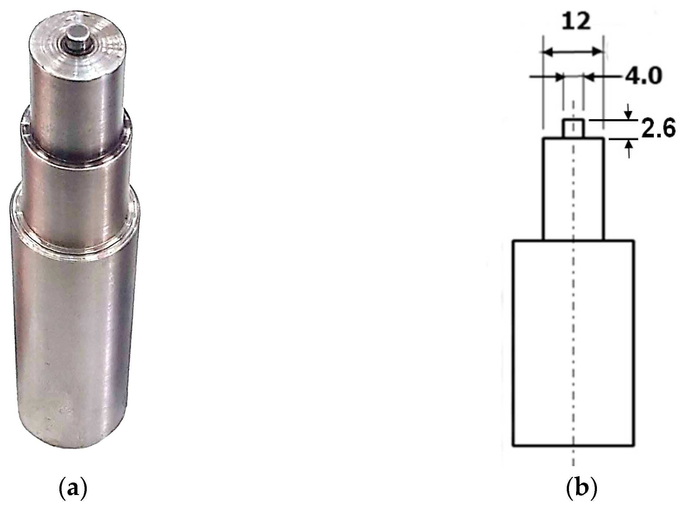
Figure 2a shows a tool made of HISI H13 tool steel that was used to perform the welding process, while the tool dimensions are schematically shown in Figure 2b.
In the present work, 1.8 mm thick AA6061-T6 sheets were used to prepare the FSSW lap-shear specimens with dimensions shown in Figure 3. The chemical composition (Wt.%) of the tested alloy is 0.81 Si, 0.48 FE, 0.28 Cu, 0.13 Mn, 0.93 Mg, 0.009 Zn, 0.25 Cr and 0.088 Ti in addition to a balance of aluminum. Table 1 includes the process variants that were considered to carry out the FSSW process using a classic milling machine. Four weld joints were produced for each welding combination of process variants. Three joints were tensile tested and averaged to determine the tensile shear fracture load, while the remaining joint was cross-sectioned and used for the microstructure and the micro-hardness examinations.
The micro-Vickers hardness test was carried out in the mid-thickness of the upper sheet of the cross-section for different welding conditions with a 0.5 mm step, a 300 gf test load, and a test cycle of 15 s.

3. Results and Discussion

3.1. Microstructure

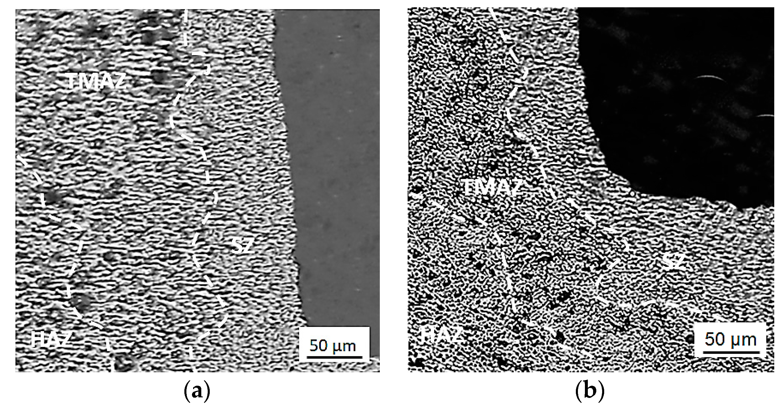
Different welding parameters produce different morphologies of the FSSW weld region due to the corresponding differences in the frictional heat generation and the material flow of each individual process [1]. Figure 4a,b represent close-up views of specimens performed during this study at different welding conditions of tool rotational speed and dwell time of 426 rpm and 15 s and 710 rpm and 10 s, respectively.
As shown in Figure 4a, a higher grain refinement was observed in the SZ of the specimen performed at a higher dwell time because of the higher heat generation, plastic deformation, and uniform distribution of precipitates in the SZ, and therefore, a full dynamic recrystallization. However, larger precipitates were observed due to the relatively longer dwell time [3,6]. On the other hand, Figure 4b shows that the specimen experienced excessive heat input as a result of the higher speed of the tool despite a lower dwell time, which did not exhibit a remarkable effect after exceeding a speed threshold of 710 rpm, and the rotational speed of the tool exhibited a higher influence on the generation of frictional heat than the dwell time. It seems to be a common metallurgical behavior, regardless of the type of metal on the work piece. This finding coincided with previous studies [3,4,5,6,7,8,9], with some specific differences in the results related to tested materials and welding conditions. This difference in morphology negatively affects the mechanical properties and the joint strength, as will be discussed later in this section.

3.2. Tensile Test

A tensile test was conducted for the performed lap joints, and the results of three specimens were averaged to determine the tensile fracture load for each individual welding condition. Figure 5 represents the tensile fracture load as a function of the speed of tool rotation at two values of dwell time, namely 10 s and 15 s. At a rotational speed of 426 rpm and a dwell time of 10 s, the tensile shear fracture load indicated 4131 N, while it indicated 5496 N at a dwell time of 15 s, with an increase of about 33%. This result was obtained due to the higher material flow and the maximum heat input required to achieve the higher refinement of grains in the SZ at the dwell time of 15 s compared to the dwell time of 10 s. The positive effect of the dwell time began to decrease with an increase in the speed of tool rotation until it reached 710 rpm. The fracture load then dramatically decreased by 14.8% and 18.5% for the 10 s and the 15 s dwell time values, respectively, with an increase in the speed of the tool to 960 rpm, affected by the excessive heat input in the weld nugget, which resulted in a coarser grain size in the SZ. This finding agrees with Ugla et al. [8]. A further increase in the dwell time no longer affected the tensile strength when the tool rotational speed exceeded 750 rpm. Thus, the dwell time exhibited a lower effect on the tensile strength compared to the speed of the tool rotation. This finding is in agreement with previous studies [4,9].
In general, the tensile shear fracture load increases with increasing the tool rotational speed and the dwell time due to the higher frictional heat generation, which results in finer grains and higher plastic deformation, while a higher increase in these two parameters leads to excessive heat input into the weld nugget, which induces a coarser grain size and a higher amount of intermetallic compounds, in addition to the formation of a larger and continuous oxide layer, and therefore, lower strength and lower TSFL [4,5,6,7,8,9].

3.3. Micro-Hardness

Figure 6 shows the Vickers hardness distribution profiles of two specimens performed at welding conditions with the tool rotational speed and the dwell time of 710 rpm and 10 s and 426 rpm and 15 s, respectively. Typical W-shaped profiles were observed because of the almost symmetrical heat inclusion, displaced material and forging force around the Keyhole [4].
A higher SZ hardness was observed with increasing the speed of the tool rotation because of the higher heat generation, which resulted in higher grain refinement and higher plastic deformation. However, a slightly lower effect of the dwell time was observed than that of the tool rotational speed. This finding was justified by Jambhale et al. [3] by the generation of higher intermetallic compounds with higher dwell time values. Therefore, the speed of tool rotation plays a dominant role in determining the hardness of the SZ of the FSSW welds [3,9].

4. Conclusions

During the present study, the effect of two of the most effective parameters of mechanical properties in the friction stir spot welding process were investigated, namely, the tool rotational speed and the dwell time. By analyzing the obtained results, it is concluded that the tool rotational speed and the dwell time were the most dominant parameters in determining the FSSW weld strength, and the tool rotational speed played the most effective role. We found that the maximum tensile shear fracture load is 5496 N at a rotational speed and dwell time of 426 rpm and 15 s. Moreover, increasing the dwell time value from 10 s to 15 s increased the tensile shear fracture load by about 33% due to the full dynamic recrystallization and grain refinement achieved by the maximum heat input and material flow, while the higher dwell time did not have a noticeable effect. In addition, when the tool rotational speed was increased from 426 rpm to 710 rpm, we observed a higher hardness of the SZ, while a higher speed resulted in a lower hardness due to the excessive heat input.

Author Contributions

Conceptualization, A.A. and D.C.; methodology, A.A.; investigation, A.A.; resources, A.A.; data curation, A.A.; writing—original draft preparation, A.A.; writing—review and editing, A.A. and D.C.; visualization, A.A. and D.C.; supervision, D.C.; project administration, A.A. and D.C. All authors have read and agreed to the published version of the manuscript.

Funding

This research received no external funding.

Institutional Review Board Statement

Not applicable.

Informed Consent Statement

Not applicable.

Data Availability Statement

Data are contained within the article and can be requested from the corresponding author.

Conflicts of Interest

The authors declare no conflicts of interest.

References

  1. Alkhafaji, A.; Camas, D.; Lopez-Crespo, P.; Al-Asadi, H. The Influence of Tool Geometry on the Mechanical Properties and the Microstructure of AA6061-T6 Aluminum Alloy Friction Stir Spot Welding. Materials 2023, 16, 4135. [Google Scholar] [CrossRef] [PubMed]
  2. Mubiayi, M.P.; Akinlabi, E.T. Friction stir spot welding between copper and aluminium: Microstructural evolution. In Proceedings of the International MultiConference of Engineers and Computer Scientists 2015, Hong Kong, China, 18–20 March 2015; Volume 2, pp. 18–20. [Google Scholar]
  3. Jambhale, S.; Kumar, S.; Kumar, S. Effect of process parameters & tool geometries on properties of friction stir spot welds: A review. Univers. J. Eng. Sci. 2015, 3, 6–11. [Google Scholar]
  4. Shen, Z.; Yang, X.; Zhang, Z.; Cui, L.; Yin, Y. Mechanical properties and failure mechanisms of friction stir spot welds of AA 6061-T4 sheets. Mater. Des. 2013, 49, 181–191. [Google Scholar] [CrossRef]
  5. Song, X.; Ke, L.; Xing, L.; Liu, F.; Huang, C. Effect of plunge speeds on hook geometries and mechanical properties in friction stir spot welding of A6061-T6 sheets. Int. J. Adv. Manuf. Technol. 2014, 71, 2003–2010. [Google Scholar] [CrossRef]
  6. Sathyaseelan, P.; Manickavasagam, V.M.; Ravichandran, P.; Prasad, D.V.S.S.S.V.; Ramana Murty Naidu, S.C.V.; Pradeep Kumar, S.; Khan, A.A.; Karthik, R.; Kerga, G.A. Effect of Dwell Time on Fracture Load of Friction Stir Spot Welded Dissimilar Metal Joints. Adv. Mater. Sci. Eng. 2022, 2022, 2163507. [Google Scholar] [CrossRef]
  7. Rojikin, S.; Muhayat, N.; Triyono. Effect of rotation speed on mechanical properties and microstructure of friction stir spot welding (FSSW) Al 5052-Steel SS400. In IOP Conference Series: Materials Science and Engineering; IOP Publishing: Bristol, UK, 2018; Volume 420, p. 012023. [Google Scholar]
  8. Ugla, A.A.; Al-Roubaiy, A.O.; Alazawi, F.H. Effect of Dwell Time and Tool Rotational Speed of Friction Stir Spot Welding on the characteristics of AA3105 joints. Univ. Thi-Qar J. Eng. Sci. 2018, 9, 51–58. [Google Scholar] [CrossRef] [PubMed]
  9. Nasir, T.; Kalaf, O.; Asmael, M. Effect of rotational speed, and dwell time on the mechanical properties and microstructure of dissimilar AA5754 and AA7075-T651 aluminum sheet alloys by friction stir spot welding. Mater. Sci. 2021, 27, 308–312. [Google Scholar] [CrossRef]
Figure 1. Schematic illustration of the FSSW process.
Engproc 56 00215 g001
Figure 2. The FSSW tool: (a) shape and design and (b) schematic illustration.
Engproc 56 00215 g002
Figure 3. Schematic of the FSSW specimen in lap configuration.
Engproc 56 00215 g003
Figure 4. Close-up views of FSSW specimens performed at different welding conditions: (a) tool rotational speed of 426 rpm and dwell time of 15 s and (b) tool rotation speed of 710 rpm and dwell time of 10 s.
Engproc 56 00215 g004
Figure 5. Tensile shear fracture load as a function of tool rotational speed at two values of dwell time (10 s and 15 s).
Engproc 56 00215 g005
Figure 6. The hardness profile of two FSSW welds performed at rotational speed and dwell time of 710 rpm and 10 s and 426 rpm and 15 s, respectively.
Engproc 56 00215 g006
Table 1. Variants considered for the FSSW process.
VariantValue
Tool rotational speed (rpm)426, 710, 960, 1400
Dwell time (s)10, 15
Plunge depth (mm)0.3
Plunge rate (mm/min)10
Disclaimer/Publisher’s Note: The statements, opinions and data contained in all publications are solely those of the individual author(s) and contributor(s) and not of MDPI and/or the editor(s). MDPI and/or the editor(s) disclaim responsibility for any injury to people or property resulting from any ideas, methods, instructions or products referred to in the content.