Proceeding Paper

Kinetic Energy Recovery of a Wind Energy Doubly-Fed Induction Generator for Grid Frequency Support †

1
Department of Electrical, Electronic, and Computer Engineering, Centre for Power Systems Research (CPSR), Cape Peninsula University of Technology, Cape Town 7535, South Africa
2
Department of Electrical, Electronic, and Computer Engineering, Centre for Distributed Power and Electronics Systems (CDPES), Cape Peninsula University of Technology, Cape Town 7535, South Africa
*
Author to whom correspondence should be addressed.
Presented at the 4th International Electronic Conference on Applied Sciences, 27 October–10 November 2023; Available online: https://asec2023.sciforum.net/.
Eng. Proc. 2023, 56(1), 247; https://doi.org/10.3390/ASEC2023-16521
Published: 1 December 2023
(This article belongs to the Proceedings of The 4th International Electronic Conference on Applied Sciences)

Abstract

:
Synchronous generators provide an inherent inertial response to frequency deviations because of their huge revolving mass that is electro-mechanically tied to the electrical network. Contrariwise, the power converters isolate the revolving mass of variable-speed wind turbines from the electric network. Therefore, they are not able to provide an inherent inertial reaction to frequency events on the electric network. This reduces the effective network inertia, which is essential for marinating the power system’s frequency. To address this problem in cases of using a wind energy doubly fed induction generator, this study introduces a kinetic energy recovery controller to the rotor-side converter.

1. Introduction

A prevailing number of megawatt-class wind turbine generators (WTGs) are variable-speed wind turbine (VSWT) generators [1,2,3]. VSWTs do not exhibit a natural inertial response to frequency events due to their mechanical and electrical control systems being decoupled [4,5,6]. Supplementary frequency control functions can be used to create a connection between the power production of the WTGs and the network frequency [7]. The virtual synchronous machine (VSM) is a concept of controlling power electronic interfaces on a power system to replicate the most desirable properties of a synchronous machine [8,9,10,11,12,13]. VSM needs to use the virtual inertia using a buffer of enough stored energy [8]. A systematic literature review (SLR) from 2015 to mid-2022 was conducted by the authors to verify the validity of the study in this research field [11]. This paper will present a kinetic energy recovery controller for wind turbines using DFIG to emulate the inertial response of synchronous generators for grid frequency support. This paper is organized as follows: Section 2 presents the mathematical modeling of the system’s components and proposed controller, Section 3 presents a case study with the IEEE-14 bus system to verify and test the adaptive frequency controller, and Section 4 presents the conclusions.

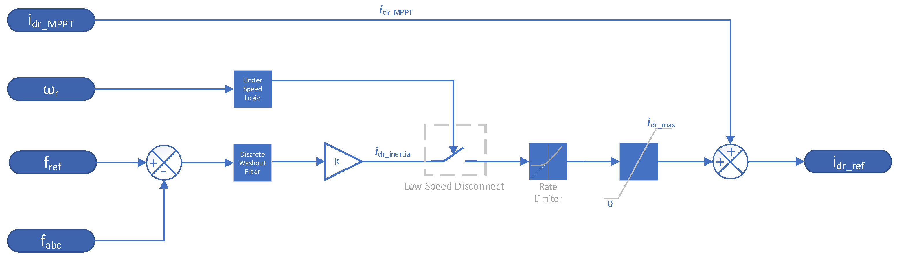
2. Mathematical Modeling

The nominal frequency of a transmission network is maintained by the balance between generation and consumption. The frequency stability of a network is a time-varying attribute where a power system is expected to continue operating following a disturbance that results in a severe imbalance between generation and load [1]. Traditional synchronous generators will naturally exhibit an inertial response [2]. This dynamic inertial response of a synchronous generator can be described mathematically by the swing Equation (1).
2 H ω s d 2 δ d t 2 = P m P e
where H is the inertia constant, ω s is the synchronous speed, and P e and P m are the respective electrical and mechanical powers, respectively.It is found that the power that can be extracted from the wind, P m , is half the air density multiplied by the cube of wind velocity [12,13] and can be expressed by (2), where ρ is the density of air; r the radius of the wind turbine; C p the wind turbine power coefficient; v w i n d the wind speed; λ the tip speed ratio; and β the pitch angle.
P m = 1 2 ρ π r 2 v w i n d 3 C p λ , β
The wind turbine power coefficient, C p , has a maximum theoretical limit of 59.3% called the Betz limit [14]. The wind turbine power coefficient shows the effect of the rotor speed and pitch angle variation on the aerodynamic power [15]. The Tip Speed ratio, λ , can be calculated by (3) [16], where ω r is the angular velocity of the wind turbine rotor.
λ = ω r r v w i n d
The pitch control is used to control the speed and the output power of the wind turbine by adjusting the pitch angle. The pitch control system is shown in Figure 1 [17].
The reference rotor speed, ω r e f , is 1.2 pu (with the synchronous rotational speed as the base value) while the output power of the wind turbine is not less than 0.75 pu (with a base value of the rated mechanical power of the wind turbine) [17]. The rotor reference speed, ω r e f , has a minimum value of 0.7 pu.
ω r e f = 0.67 P D F I G 2 + 1.42 P D F I G + 0.51
The mechanical power and the electrical output power of the stator are computed by (5), where P m is the power transmitted to the rotor that has been captured by the wind turbine, ω r is the rotational speed of the rotor, and P s is the electrical output power of the stator [18].
P m = T m ω r P s
For a lossless generator, the mechanical equation which describes the dynamic behavior of the rotor mechanical speed in terms of the mechanical torque, T m , and the electromagnetic torque, T e m , is given by (6) [19].
J d ω r d t = T m T e m
This study will be using the average model since the focus of this study is the interaction between the DFIG control system and the power system [20]. The frequency support controller shown in Figure 2 emulates an inertial response by injecting additional power during a frequency disturbance by increasing the d-axis rotor reference current.

3. Case Study

The test system used in this study is based on the modified IEEE 14-bus system used in [16], as shown in Figure 3. The modified IEEE 14-bus system consists of two voltage zones, connected by T1, T2 and T3. Buses 1 through 5 form part of the 132 kV zone while busses 6 through 14 form part of the 33 kV zone. The modified 14-bus system includes synchronous generators, 11 static loads and an aggregated wind farm model. The aggregated wind farm subsystem consists of 80, 1.5 MW class DFIG WTs. The effects of the frequency support controller on consecutive disturbances are studied below.

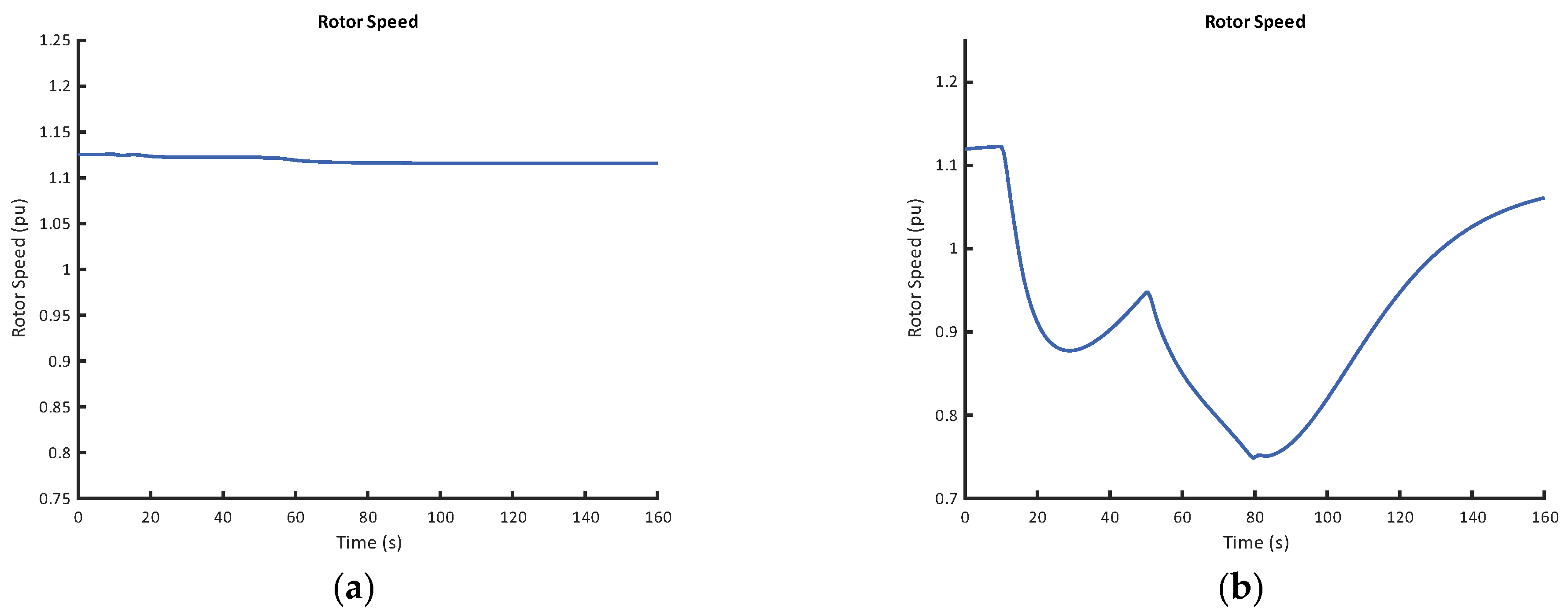
Case Study: Wind Speed Condition of 10 m/s with a Consecutive Disturbance

A generator generating 130 MW is tripped at 10 s and an additional generator is tripped at 50 s with wind speed conditions of 10 m/s. Figure 4a shows the frequency support of an MPPT-operated DFIG-based wind farm. The frequency nadir of the first disturbance is 49.125 Hz, while the frequency nadir caused by the second disturbance is 49.288 Hz.
Figure 4b shows the results of the DFIG-based wind farm partaking in frequency support. In Figure 4b, the first frequency nadir of 49.4 Hz is reached at 13.8 s following the first disturbance at 10 s. The system frequency recovers to 49.62 Hz prior to the second disturbance occurring and following this second disturbance at 50 s, a frequency nadir of 49.44 Hz is reached at 51.6 s.
The system frequency recovers 49.53 Hz at 79 s following the consecutive disturbances. However, at this point, the system frequency succumbs to another frequency deviation as the rotor speed reaches its minimum speed, and under speed logic reduces the frequency support controller contribution to zero.
The WPP output of the MPPT-operated DFIG-based wind farm is shown in Figure 5a. The MPPT-operated DFIG-based wind farm shows no significant increase in output power when subjected to consecutive disturbances. The WPP output of the DFIG-based wind farm with frequency support is shown in Figure 5b. The WPP output begins to rise rapidly when the disturbance occurs at 10 s and peaks at 114.6 MW. After the peak, the WPP output begins to decline as the system frequency approaches a new steady state but continues to decline below the pre-disturbance WPP output power of 72.55 MW to 61.2 MW at 39.2 s due to the rotor recovering its speed. When the second disturbance occurs at 50 s, the WPP output power rises to 84.8 MW at 51.8 s to overcome the frequency disturbance caused by the second generator tripping. The WPP output power begins to decline as the system frequency begins to recover and continues to decline below 61.2 MW as the rotor has deviated considerably from its optimal speed. The WPP output power reaches a minimum output of 47.2 MW at 80.3 s as the under-speed logic negates the contribution frequency support controller. The WPP output power has a non-monotonic increase to 69.1 MW as the rotor speed recovers.
The rotor speed of the MPPT-operated DFIG-based wind farm in Figure 6a shows no significant deviation in rotor speed following two consecutive disturbances at 10 s and at 50 s. However, the rotor speed of the DFIG-based wind farm with frequency support shown in Figure 6b, begins to decrease when the disturbance occurs at 10 s to a minimum speed of 0.87 pu at 28.9 s. The rotor speed recovers to a speed of 0.94 pu prior to the second disturbance at 50 s which occurs during the rotor recovery phase. The rotor speed begins to decline at the instance of the second as the kinetic energy is recovered to support the system frequency. The rotor speed following the second disturbance reaches a minimum speed of 0.75 pu at 79.6 s when the under-speed logic is triggered. This prevents any further exchange of kinetic energy from the rotor to electrical energy and leads to the third frequency drop to 49.45 Hz seen in Figure 6. The rotor recovers monotonically from its minimum speed to 1.05 pu.

4. Conclusions

The frequency support controller emulates an inertial response by temporarily raising the active power output of the wind turbine generator during a frequency disturbance. The additional energy required for the temporary overproduction of active power during a frequency disturbance is obtained by recovering the kinetic energy of the spinning mass of the wind turbine generator. Future work should aim to extend the frequency support performance of the WTG in low wind conditions and varying wind speed conditions.

Author Contributions

Conceptualization, A.B. and K.M.A.-A.-E.; methodology, A.B.; software, A.B.; validation, A.B., K.M.A.-A.-E. and M.A.; formal analysis, A.B.; investigation, K.M.A.-A.-E.; resources, M.A.; data curation, M.A.; writing—original draft preparation, A.B.; writing—review and editing, K.M.A.-A.-E.; visualization, A.B.; supervision, K.M.A.-A.-E. and M.A.; project administration, K.M.A.-A.-E.; funding acquisition, K.M.A.-A.-E. All authors have read and agreed to the published version of the manuscript.

Funding

This research received no external funding.

Institutional Review Board Statement

Not applicable.

Informed Consent Statement

Not applicable.

Data Availability Statement

Data are contained within the article.

Conflicts of Interest

The authors declare no conflicts of interest.

References

  1. Musau, M.P.; Chepkania, T.L.; Odero, A.N.; Wekesa, C.W. Effects of renewable energy on frequency stability: A proposed case study of the Kenyan grid. In Proceedings of the 2017 IEEE PES-IAS PowerAfrica Conference: Harnessing Energy, Information and Communications Technology (ICT) for Affordable Electrification of Africa, PowerAfrica 2017, Accra, Ghana, 27–30 June 2017; pp. 12–15. [Google Scholar] [CrossRef]
  2. Ulbig, A.; Borsche, T.S.; Andersson, G. Impact of low rotational inertia on power system stability and operation. IFAC Proc. Vol. 2014, 47, 7290–7297. [Google Scholar] [CrossRef]
  3. Walling, R.A.; Gursoy, E.; English, B. Current contributions from Type 3 and Type 4 wind turbine generators during faults. In Proceedings of the PES T&D 2012, Orlando, FL, USA, 7–10 May 2012; pp. 1–6. [Google Scholar] [CrossRef]
  4. Kim, Y.-S.; Chung, I.-Y.; Moon, S.-I. An Analysis of Variable-Speed Wind Turbine Power-Control Methods with Fluctuating Wind Speed. Energies 2013, 6, 3323–3338. [Google Scholar] [CrossRef]
  5. Wang, Y.; Meng, J.; Zhang, X.; Xu, L. Control of PMSG-Based Wind Turbines for System Inertial Response and Power Oscillation Damping. IEEE Trans. Sustain. Energy 2015, 6, 565–574. [Google Scholar] [CrossRef]
  6. Boyle, J.; Littler, T.; Foley, A. Review of frequency stability services for grid balancing with wind generation. J. Eng. 2018, 2018, 1061–1065. [Google Scholar] [CrossRef]
  7. Xu, G.; Ge, D.; Cao, T. Combined deload and kinetic energy control of variable speed wind turbines for frequency support. In Proceedings of the 2016 IEEE PES Asia-Pacific Power and Energy Engineering Conference (APPEEC), Xi’an, China, 25–28 October 2016; pp. 890–894. [Google Scholar] [CrossRef]
  8. D’Arco, S.; Suul, J.A.; Fosso, O.B. A Virtual Synchronous Machine implementation for distributed control of power converters in SmartGrids. Electr. Power Syst. Res. 2015, 122, 180–197. [Google Scholar] [CrossRef]
  9. Fang, J.; Li, X.; Tang, Y.; Li, H. Design of virtual synchronous generators with enhanced frequency regulation and reduced voltage distortions. In Proceedings of the IEEE Applied Power Electronics Conference and Exposition—APEC, San Antonio, TX, USA, 4–8 March 2018; pp. 1412–1419. [Google Scholar] [CrossRef]
  10. Zheng, T.; Chen, L.; Guo, Y.; Mei, S. Comprehensive control strategy of virtual synchronous generator under unbalanced voltage conditions. IET Gener. Transm. Distrib. 2018, 12, 1621–1630. [Google Scholar] [CrossRef]
  11. Bhowon, A.; Abo-Al-Ez, K.M.; Adonis, M. Variable-Speed Wind Turbines for Grid Frequency Support: A Systematic Literature Review. Mathematics 2022, 10, 3586. [Google Scholar] [CrossRef]
  12. Kumar, T.V.; Thomas, V.; Kumaravel, S.; Ashok, S. Performance of virtual synchronous machine in autonomous mode of operation. In Proceedings of the 2018 5th International Conference on Renewable Energy: Generation and Applications (ICREGA), Al Ain, United Arab Emirates, 25–28 February 2018; pp. 310–314. [Google Scholar] [CrossRef]
  13. Huleihil, M.; Mazor, G. Wind Turbine Power: The Betz Limit and Beyond. In Advances in Wind Power; InTech: London, UK, 2012; p. 13. [Google Scholar] [CrossRef]
  14. Khurshid, A.; Mughal, M.A.; Othman, A.; Al-Hadhrami, T.; Kumar, H.; Khurshid, I.; Arshad; Ahmad, J. Optimal Pitch Angle Controller for DFIG-Based Wind Turbine System Using Computational Optimization Techniques. Electronics 2022, 11, 1290. [Google Scholar] [CrossRef]
  15. Yang, D.; Jin, Z.; Zheng, T.; Jin, E. An adaptive droop control strategy with smooth rotor speed recovery capability for type III wind turbine generators. Int. J. Electr. Power Energy Syst. 2022, 135, 107532. [Google Scholar] [CrossRef]
  16. Yang, D.; Gao, H.-C.; Zhang, L.; Zheng, T.; Hua, L.; Zhang, X. Short-term frequency support of a doubly-fed induction generator based on an adaptive power reference function. Int. J. Electr. Power Energy Syst. 2020, 119, 105955. [Google Scholar] [CrossRef]
  17. Chang, K.; Xue, F.; Fang, Y.; Yu, Y. Comparative simulation of dynamic characteristics of wind turbine doubly-fed induction generator based on RTDS and MATLAB. In Proceedings of the 2010 International Conference on Power System Technology: Technological Innovations Making Power Grid Smarter, POWERCON2010, Hangzhou, China, 24–28 October 2010. [Google Scholar] [CrossRef]
  18. Fletcher, J.; Yang, J. Introduction to the Doubly-Fed Induction Generator for Wind Power Applications, Paths to Sustainable Energy. 30 December 2010. Available online: http://www.intechopen.com/books/paths-to-sustainable-energy/introduction-to-the-doubly-fed-inductiongenerator-%0Afor-wind-power-applications (accessed on 2 December 2023).
  19. The MathWorks Inc. Implement Phasor Model of Variable Speed Doubly-Fed Induction Generator Driven by Wind Turbine—Simulink—MathWorks United Kingdom; The MathWorks Inc.: Natick, MA, USA, 2019; Available online: https://uk.mathworks.com/help/physmod/sps/powersys/ref/windturbinedoublyfedinductiongeneratorphasortype.html (accessed on 19 October 2019).
  20. The MathWorks Inc. Wind Farm—DFIG Average Model—MATLAB & Simulink—MathWorks United Kingdom; The MathWorks Inc.: Natick, MA, USA, 2022; Available online: https://uk.mathworks.com/help/physmod/sps/ug/wind-farm-dfig-average-model.html (accessed on 10 August 2022).
Figure 1. Pitch control system block diagram.
Engproc 56 00247 g001
Figure 2. Adapted frequency support controller.
Engproc 56 00247 g002
Figure 3. Single line diagram of a modified IEEE 14-Bus System [16].
Engproc 56 00247 g003
Figure 4. (a) System frequency with no frequency support from DFIG-based wind farm. (b) System frequency with frequency support from DFIG-based wind farm.
Engproc 56 00247 g004
Figure 5. (a) Case 3 WPP output with no frequency support from DFIG-based wind farm. (b) Case 3 WPP output with frequency support from DFIG-based wind farm.
Engproc 56 00247 g005
Figure 6. (a) Rotor speed with no frequency support from DFIG-based wind farm. (b) Rotor Speed with frequency support from DFIG-based wind farm.
Engproc 56 00247 g006
Disclaimer/Publisher’s Note: The statements, opinions and data contained in all publications are solely those of the individual author(s) and contributor(s) and not of MDPI and/or the editor(s). MDPI and/or the editor(s) disclaim responsibility for any injury to people or property resulting from any ideas, methods, instructions or products referred to in the content.

