Abstract
Unbalanced loads are extremely prevalent in real systems, and they create power quality issues for the UPS system. To address this problem, this work provides an optimal voltage control scheme for a three-phase inverter using the linear matrix inequality method. In addition, the purpose of this controller is to provide a well-balanced three-phase sinusoidal voltage regardless of the imbalance of the loads. This symmetrical component-based controller features two paralleled voltage controls: a positive sequence to regulate output signals and a negative sequence to eliminate unbalanced voltages. Along with that, the optimization problem is formulated such that the convergence rate is maximized to obtain the output voltage as swiftly as possible. PSIM is used to carry out the simulation, and MATLAB is utilized to assist in determining the optimal control gain for the state feedback and integral control of each sequence. The control algorithm is then deployed utilizing an in-house designed control board together with a TMS320F28335 digital signal processor. To determine the efficacy of the proposed control, simulation, and experiment results are compared to those of an optimal controller without a negative sequence.
1. Introduction
The purpose of UPS inverters is to safeguard vital equipment and appliances from the negative effects of power outages by maintaining a constant power supply to them. To ensure that the voltage quality is well regulated, a lot of research has been conducted, such as reducing the output voltage distortion [1], improving transient performance [2,3,4], and increasing robustness [5,6]. However, the above-mentioned methods have not taken the unbalanced load conditions into account. When the voltage levels in each phase of a three-phase system are unequal, unbalanced three-phase voltage issues occur. This imbalance can also be caused by a variety of factors, including unequal loads, defective equipment, and distribution system problems. In such instances, the voltage magnitude and phase angles vary between the phases, which may cause operational issues with electrical devices and equipment. To address this problem, this paper presents a systematic control design with optimal gain computation to provide fast output performance and a well-balanced three-phase voltage even under unequal load conditions. The controller is based on dual-voltage control for positive and negative sequences with the purpose of regulating the output signals and eliminating unbalanced voltage, respectively. The process of gain computation is based on previous work [7] using LMI-based optimization to achieve fast transient performance. The control algorithm is implemented on TMS320F28335 for the inverter prototype at a sampling frequency of 10 kHz. Finally, the simulation and experimentation are discussed with the comparison of the controller without the negative sequence compensator to verify the control performance.
2. Inverter Modeling under Unbalanced Loads
Generally, three-phase unbalanced signals can be split into three sequences: positive, negative, and zero sequences [8]. The proposed three-wire inverter, however, is without the zero-sequence due to the lack of the floating point. As a result, the unbalanced voltage and current can be rewritten as the following using the two sequences:
The positive with superscript p and negative sequence n voltage can be defined using as follows [9]:
where and are 120° and 240° phase-shifting operator, respectively. However, the implementation of these phase-shifting operators is practically challenging. Therefore, the use of all-pass filters is employed as a 90° phase-shifter associated with j instead [10,11] since and . Then, the positive and negative sequence in can be rewritten as
The implementation of an all-pass filter for imaginary part j can be found in previous work [12,13]; the same process can be carried out to calculate the positive and negative sequence currents.
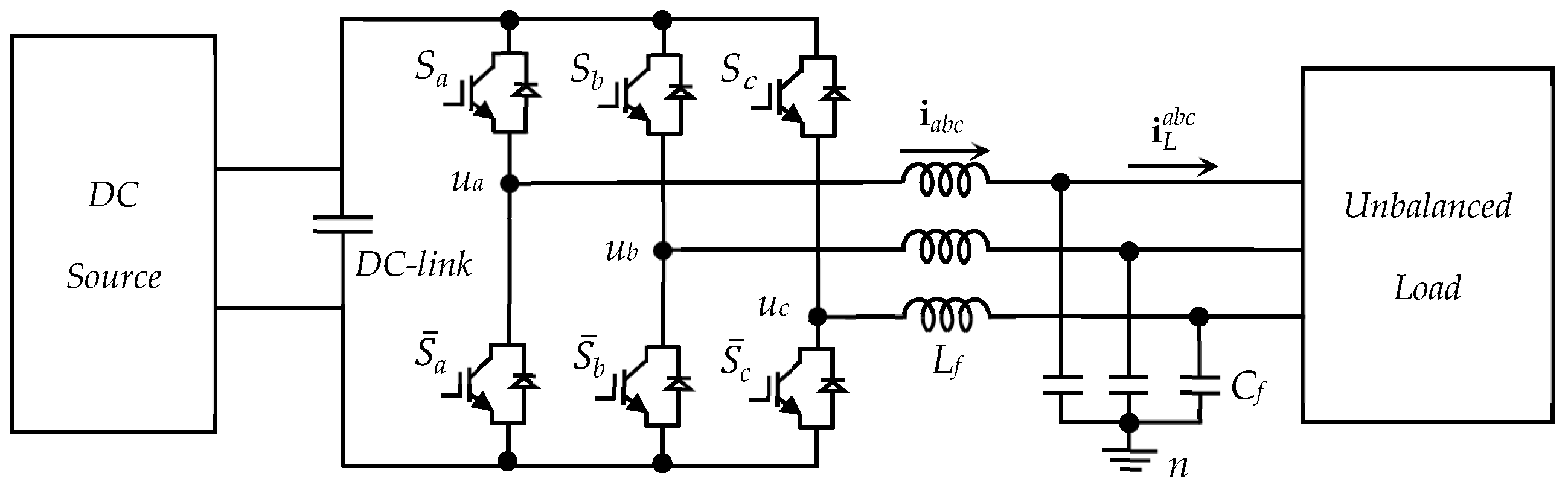
The continuous-time state–space model of the proposed three-phase inverter in Figure 1 can be obtained using Kirchoff’s laws for both positive and negative sequences and converted to the dq-frame [4,14] as follows:
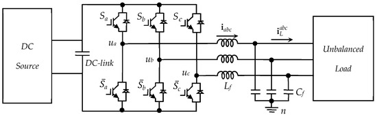
Figure 1.
Three-phase UPS inverter under unbalanced loads.
The only difference between the models of these two sequences is the sign of the angular frequency , which is inverted due to the opposite rotational direction of the negative sequence [15]. The model (6) and (7) can be rewritten in compact form as
The continuous-time model (8) and (9) of the inverter can be discretized as follows:
where , , , , I is a 4th-order identity matrix, and h is the sampling time.
3. Proposed Control and Optimal Gain
Due to the fact that the same design method can be applied to both positive and negative sequence controllers, the design procedure is unified. The control law acquired from [16,17,18] is used to eliminate offset errors and provide system stability.
where u, , , , and are the control input, vector of integral state, reference state, state feedback gain set, and integral control gain set, respectively. The output matrix C is defined as where and are 2 × 2 zero and the identical matrix, respectively. In order to regulate the output voltage, d-voltage should be set to and q-voltage should be set to zero. In addition, all negative sequence voltages should be set to zero to eradicate the unbalanced voltage. Therefore, the reference state for both sequences can be determined as and .
To determine the control gain and , the system state vector and integral state vector can be augmented and written in compact form as
where , , , , is a 2 by 2 zero matrix and is the second-order identity matrix. The control input u(k) is defined as
Then, from (13) and (14), the overall closed-loop system can be obtained assuming that the matrix D = 0 as
The augmented closed-loop system (15) is stable if the inequality (16) holds.
where , is a positive definite matrix, K is a stabilizing gain set, and .
To shorten the convergence time of the output voltage to the steady state, ε should be selected with respect to the minimizing of under the LMI condition (16). Then, the optimization problem can be defined as
Then, [19,20,21] the optimal gain can be obtained as
To efficiently solve this LMI problem, a MATLAB toolbox called YALMIP is used to compute the optimal gain.
4. Simulation and Experimental Results
Simulation and experimental results are discussed in this section. MATLAB and PSIM are employed to conduct this simulation. Using the YALMIP toolkit, the optimal gain can be easily determined after a methodical design procedure has been outlined. The computed gain is then used in the PSIM-implemented C language control algorithm. Table 1 contains the UPS inverter’s specifications. It is noteworthy that the resistive loads are connected in a delta configuration to produce a large imbalanced dip for the purpose of verifying the control algorithm.

Table 1.
Parameters used in simulation studies.
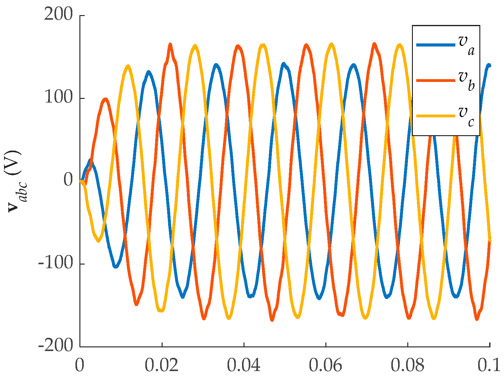
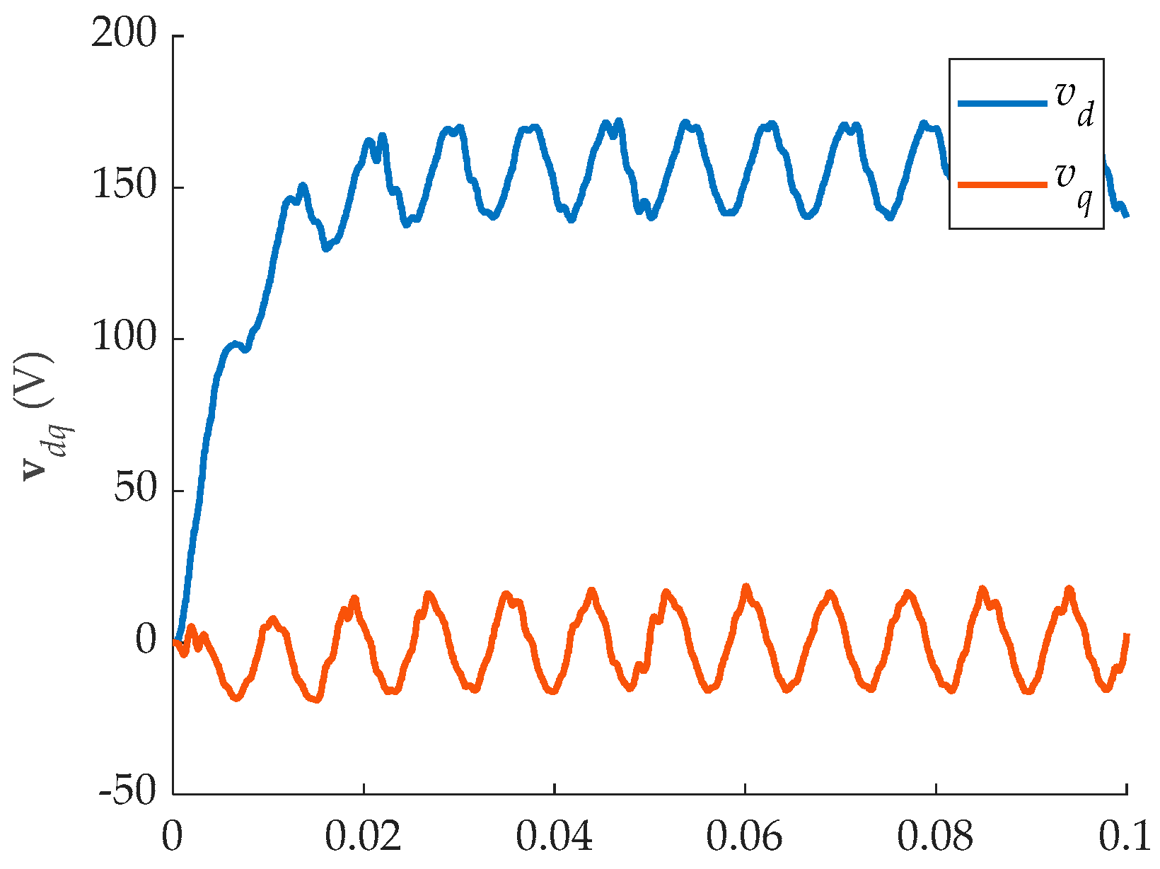
Figure 2 displays the controller’s output voltage performance in the abc-frame without the negative sequence controller. It comes out that a significant voltage imbalance occurs at the output. Moreover, Figure 3 depicts that the unbalanced voltage in the abc-frame corresponds to the double frequency oscillation in the dq-frame.
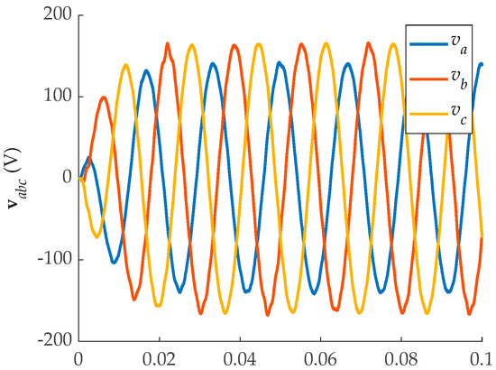
Figure 2.
Simulation results of output voltage in abc-frame without negative controller.
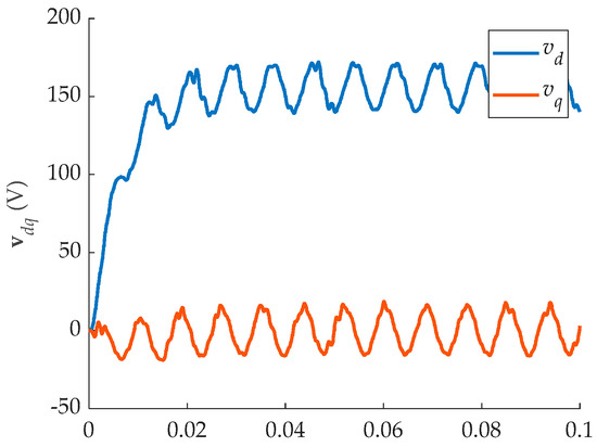
Figure 3.
Simulation results of output voltage in dq-frame without negative controller.
Figure 2 displays the controller’s output voltage performance in the abc-frame without the negative sequence controller. It is revealed that a significant voltage imbalance occurs at the output. Moreover, Figure 3 depicts that the unbalanced voltage in the abc-frame corresponds to the double frequency oscillation in the dq-frame.
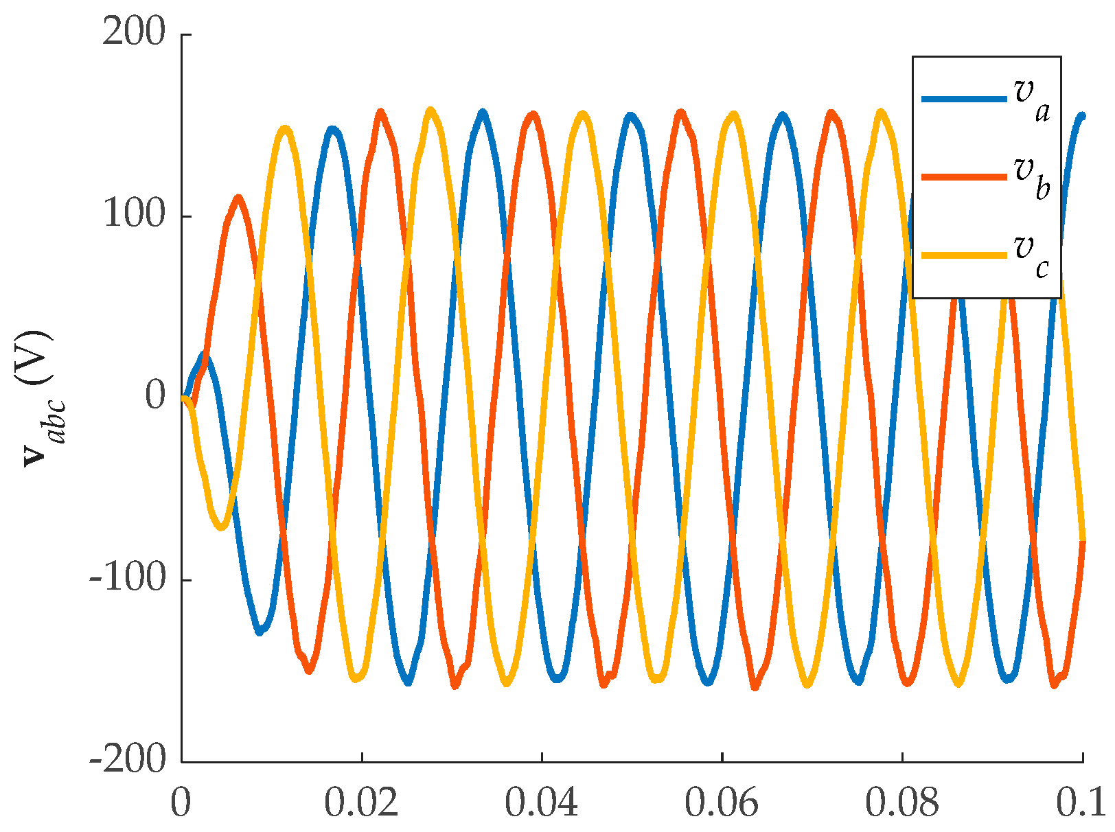
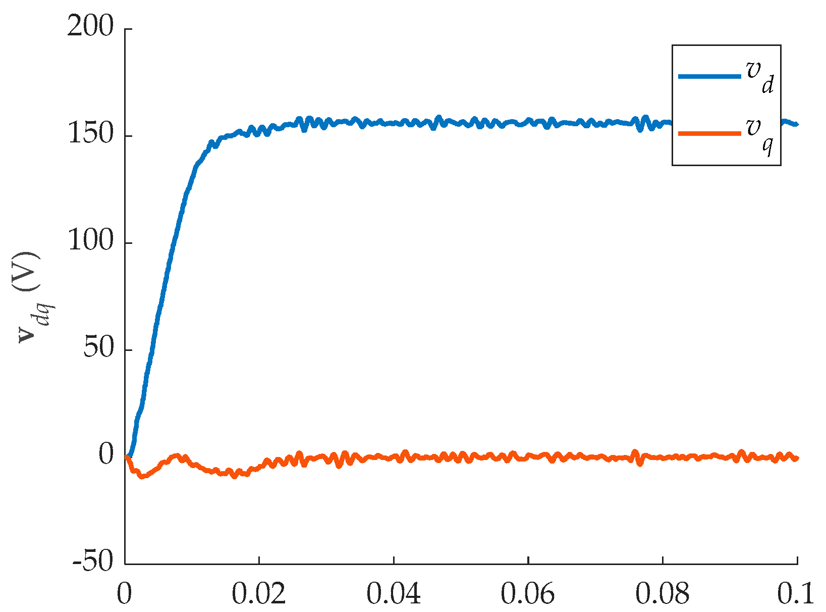
In contrast to the results of the controller without a negative sequence compensator, the output voltage of the controller with an additional negative sequence controller is neither asymmetrical nor oscillatory, as shown in Figure 4 and Figure 5, respectively.

Figure 4.
Simulation results of the proposed method in abc-frame.
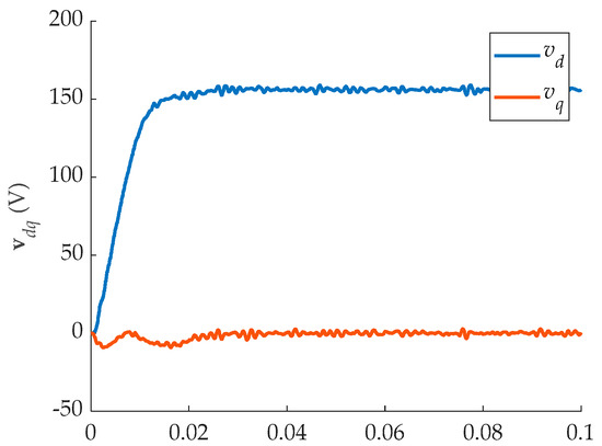
Figure 5.
Simulation results of the proposed method in dq-frame.
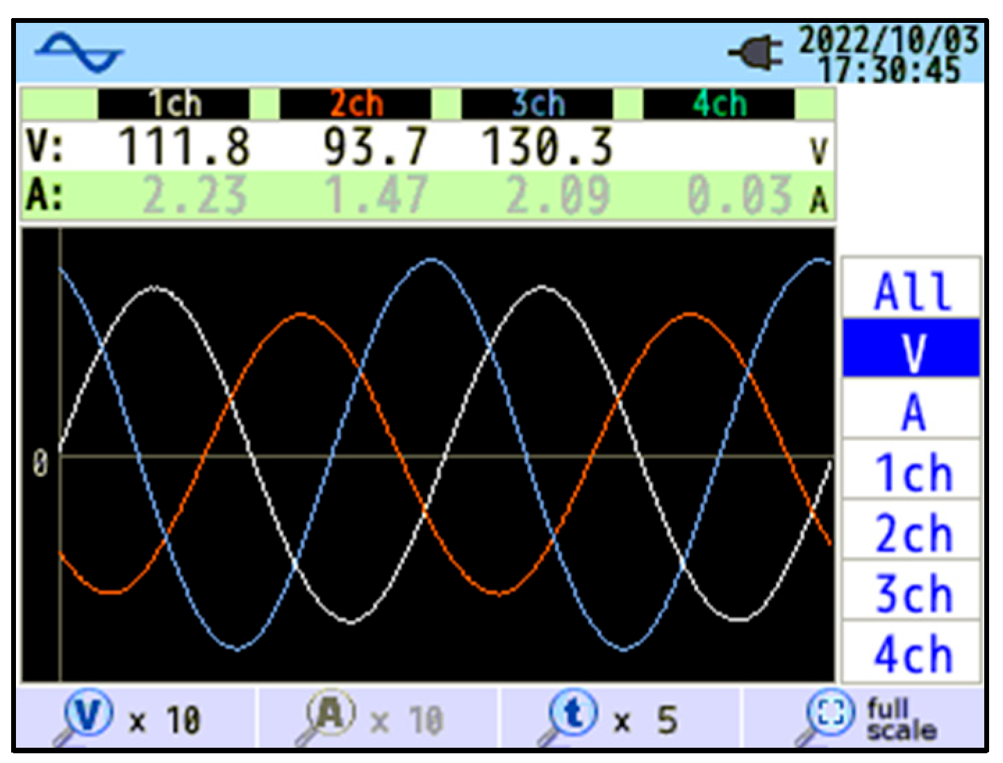
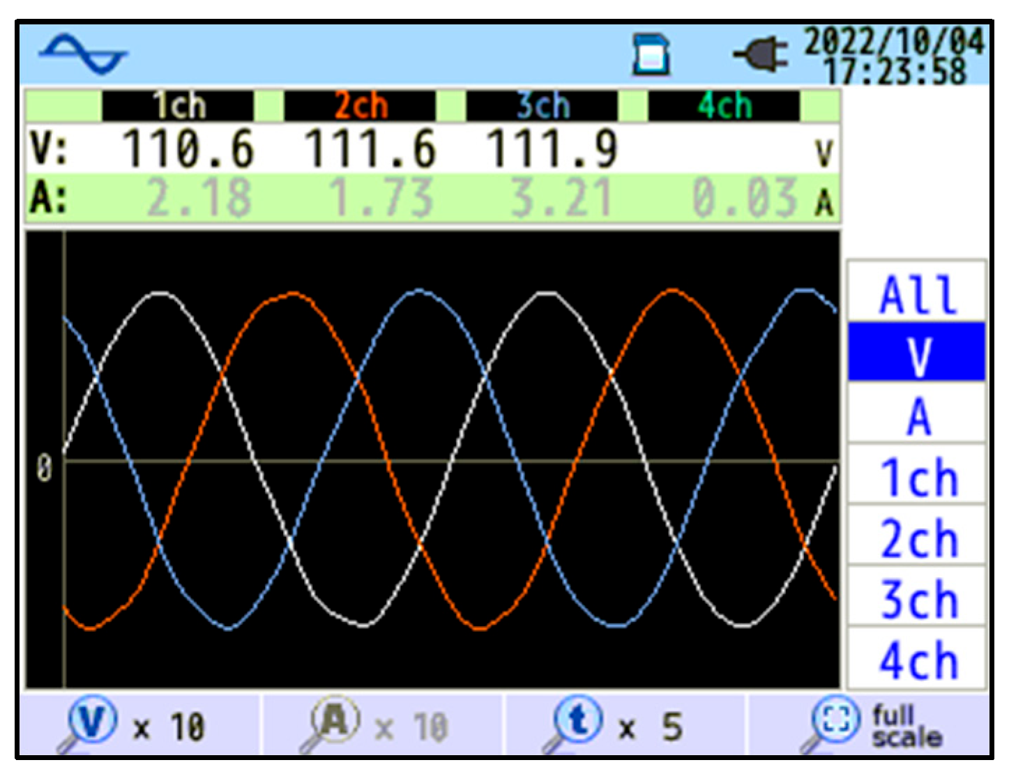
Figure 6 depicts the outcome of the experiments conducted without the use of a negative sequence compensator. It is obvious that the output voltage results are more enhanced with well-balanced sinusoidal control utilizing the proposed control, as shown in Figure 7. This is the case since the results are significantly better.

Figure 6.
Experimental results without negative sequence control.

Figure 7.
Experimental results of the proposed control.
5. Conclusions
Using the LMI method, this paper proposes a systematic control design for an inverter under unbalanced load conditions. For the controller to regulate the output voltage and eliminate the unbalanced voltage, two sets of controllers for the positive and negative sequences are required. Simulations and experiments of this proposed controller exhibit superior performance in terms of three-phase symmetrical voltage when compared to controllers lacking a negative sequence compensator. With the computed gain using the LMI method, the rapid transient response is obtained. Furthermore, an additional negative sequence controller aids in eliminating the unbalanced voltage. Lastly, future work on this study will include disturbance or state observers to reduce the state measuring noise to obtain better output results.
Author Contributions
Conceptualization, C.C.; methodology, C.C.; software, H.T.; validation, P.S., S.E. and H.T.; formal analysis, C.C.; investigation, C.C.; resources, P.S.; data curation, H.T.; writing—original draft preparation, C.C.; writing—review and editing, C.C.; visualization, S.E.; supervision, S.S.; project administration, H.T.; funding acquisition, S.S. All authors have read and agreed to the published version of the manuscript.
Funding
This research received no external funding.
Institutional Review Board Statement
Not applicable.
Informed Consent Statement
Not applicable.
Data Availability Statement
The data used to support the findings of this study are available from the corresponding author upon reasonable request.
Conflicts of Interest
The authors declare that they have no conflict of interest.
References
- Wu, T.-F.; Huang, Y.-H.; Temir, S.; Chan, C.-C. 3Φ4W Hybrid Frequency Parallel Uninterruptable Power Supply for Reducing Voltage Distortion and Improving Dynamic Response. IEEE J. Emerg. Sel. Top. Power Electron. 2022, 10, 906–918. [Google Scholar] [CrossRef]
- Seyedalipour, S.S.; Shahparasti, M.; Hajizadeh, A.; Savaghebi, M. Model-based Control of Four-leg Inverter for UPS Applications Considering the Effect of Neutral Line Inductor. IET Power Electron. 2021, 14, 1468–1479. [Google Scholar] [CrossRef]
- Pichan, M.; Rastegar, H. Sliding-Mode Control of Four-Leg Inverter With Fixed Switching Frequency for Uninterruptible Power Supply Applications. IEEE Trans. Ind. Electron. 2017, 64, 6805–6814. [Google Scholar] [CrossRef]
- Danayiyen, Y.; Altaş, İ.H.; Lee, Y.I. Robust Discrete Time Disturbance Observer with Finite Control Set Model Predictive Control in UPS System. IFAC-Pap. 2019, 52, 51–56. [Google Scholar] [CrossRef]
- Oliveira, T.; Caseiro, L.; Mendes, A.; Cruz, S.; Perdigão, M. Model Predictive Control for Paralleled Uninterruptible Power Supplies with an Additional Inverter Leg for Load-Side Neutral Connection. Energies 2021, 14, 2270. [Google Scholar] [CrossRef]
- Bayhan, S.; Seyedalipour, S.S.; Komurcugil, H.; Abu-Rub, H. Lyapunov Energy Function Based Control Method for Three-Phase UPS Inverters With Output Voltage Feedback Loops. IEEE Access 2019, 7, 113699–113711. [Google Scholar] [CrossRef]
- Choeung, C.; Tang, H.; Soth, P.; Keo, S.; Leang, P.; Cheng, H.; Srang, S.; Huy, V. Linear Matrix Inequality-Based Optimal State Feedback Control of a Three-Phase L-Filtered Grid-Connected Inverter. In Proceedings of the 2023 Third International Symposium on Instrumentation, Control, Artificial Intelligence, and Robotics (ICA-SYMP), Bangkok, Thailand, 18 January 2023; pp. 135–139. [Google Scholar]
- Fortescue, C.L. Method of Symmetrical Co-Ordinates Applied to the Solution of Polyphase Networks. Trans. Am. Inst. Electr. Eng. 1918, XXXVII, 1027–1140. [Google Scholar] [CrossRef]
- Lyon, W.V. Applications of the Method of Symmetrical Components; McGraw-Hill Book Company, Incorporated: Columbus, OH, USA, 1937. [Google Scholar]
- Iravani, M.R.; Karimi-Ghartemani, M. Online Estimation of Steady State and Instantaneous Symmetrical Components. IEEE Proc.-Gener. Transm. Distrib. 2003, 150, 616–622. [Google Scholar] [CrossRef]
- Teodorescu, R.; Liserre, M.; Rodríguez, P. Grid Converters for Photovoltaic and Wind Power Systems; Wiley: Piscataway, NJ, USA; Chichester, UK; Hoboken, NJ, USA, 2011; ISBN 978-0-470-05751-3. [Google Scholar]
- Choeung, C.; Kry, M.L.; Lee, Y.I. Robust Tracking Control of a Three-Phase Charger under Unbalanced Grid Conditions. Energies 2018, 11, 3389. [Google Scholar] [CrossRef]
- Tang, H.; In, S.; Soth, P.; Soeng, S.; Cheng, H.; Huy, V.; Srang, S.; Choeung, C. Design of a Robust Control for a Single-Phase AC-DC Converter Using LMI Technique. In Proceedings of the 2023 International Electrical Engineering Congress (iEECON), Krabi, Thailand, 8 March 2023; pp. 1–5. [Google Scholar]
- Huy, V.; Tang, H.; Soth, P.; Yay, S.; Sovan, K.; Choeung, C. Three-Phase Inverter Using Robust Tracking Control Based Interpolation. In Proceedings of the 2023 Third International Symposium on Instrumentation, Control, Artificial Intelligence, and Robotics (ICA-SYMP), Bangkok, Thailand, 18 January 2023; pp. 91–95. [Google Scholar]
- Mirhosseini, M.; Pou, J.; Karanayil, B.; Agelidis, V.G. Positive- and Negative-Sequence Control of Grid-Connected Photovoltaic Systems under Unbalanced Voltage Conditions. In Proceedings of the 2013 Australasian Universities Power Engineering Conference (AUPEC), Hobart, Australia, 29 September–3 October 2013; pp. 1–6. [Google Scholar]
- Lim, J.S.; Park, C.; Han, J.; Lee, Y.I. Robust Tracking Control of a Three-Phase DC–AC Inverter for UPS Applications. IEEE Trans. Ind. Electron. 2014, 61, 4142–4151. [Google Scholar] [CrossRef]
- Soth, P.; Tang, H.; So, B.; San, S.; Cheng, H.; Choeung, C.; Srang, S.; Or, C. Robust Dual-Current Control of a Three-Phase Grid-Tied Inverter under Unbalanced Grid Voltage Using LMI Approach. In Proceedings of the 2023 International Electrical Engineering Congress (iEECON), Krabi, Thailand, 8 March 2023; pp. 6–11. [Google Scholar]
- Choeung, C.; Tang, H.; Soth, P.; Huy, V.; Srang, S. LMI-Based Robust Voltage Regulation of a Single-Phase Inverter with LC-Filtered Output. In Computational Intelligence Methods for Green Technology and Sustainable Development; Huang, Y.-P., Wang, W.-J., Quoc, H.A., Le, H.-G., Quach, H.-N., Eds.; Lecture Notes in Networks and Systems; Springer International Publishing: Cham, Switzerland, 2023; Volume 567, pp. 314–324. ISBN 978-3-031-19693-5. [Google Scholar]
- Lai, N.-B.; Kim, K.-H. Robust Control Scheme for Three-Phase Grid-Connected Inverters With LCL-Filter Under Unbalanced and Distorted Grid Conditions. IEEE Trans. Energy Convers. 2018, 33, 506–515. [Google Scholar] [CrossRef]
- Lim, J.S.; Lee, Y.I. Design of a Robust Controller for Three-Phase UPS Systems Using LMI Approach. In Proceedings of the International Symposium on Power Electronics Power Electronics, Electrical Drives, Automation and Motion, Sorrento, Italy, 22–24 June 2012; pp. 654–657. [Google Scholar]
- Choeung, C.; Kry, M.L.; Lee, Y.-I. Robust Tracking Control of a Three-Phase Bidirectional Charger for Electric Vehicle. J. Adv. Transp. 2022, 2022, 1–12. [Google Scholar] [CrossRef]
Disclaimer/Publisher’s Note: The statements, opinions and data contained in all publications are solely those of the individual author(s) and contributor(s) and not of MDPI and/or the editor(s). MDPI and/or the editor(s) disclaim responsibility for any injury to people or property resulting from any ideas, methods, instructions or products referred to in the content. |
© 2023 by the authors. Licensee MDPI, Basel, Switzerland. This article is an open access article distributed under the terms and conditions of the Creative Commons Attribution (CC BY) license (https://creativecommons.org/licenses/by/4.0/).