Proceeding Paper

M-Shaped Conformal Antenna with FSS Backing for Gain Enhancement †

by
Madhavi Devi Lanka
* and
Subbarao Chalasani
School of Engineering, Career Point University, Kota 324005, Rajasthan, India
*
Author to whom correspondence should be addressed.
Presented at the International Conference on Recent Advances in Science and Engineering, Dubai, United Arab Emirates, 4–5 October 2023.
Eng. Proc. 2023, 59(1), 143; https://doi.org/10.3390/engproc2023059143
Published: 4 January 2024
(This article belongs to the Proceedings of Eng. Proc., 2023, RAiSE-2023)

Abstract

:
A frequency selective surface (FSS) integrated conformal antenna is modelled and analytical study is presented in this article. A novel antenna design known as the “M-shaped Conformal Antenna with FSS Backing for Gain Improvement” makes use of both the conformal structure and FSS technology to increase gain. The geometric shape of the M-shaped antenna, which might resemble the letter “M” or a collection of M-shaped parts, is what gives it its name. This structure can be created to alter the antenna’s resonance frequency, increase bandwidth, or adjust the emission pattern. The radiation pattern of the antenna may be precisely controlled by combining an M-shaped construction with an FSS. You may customize the radiation pattern to concentrate energy in particular directions or sectors, boosting gain and coverage, when necessary, by modifying the FSS’s geometry and physical characteristics. The combination of features makes it extremely ideal for a variety of applications where optimum gain is a crucial need, such as aerospace, communications, and radar arrays. It also enables fine control of the radiation pattern, frequency-selective gain, and interference elimination. The designed antenna consists of an M-shaped model on the visible sideways along with a complement split ring resonator and a defective ground structure on the bottom side. Antenna resonating at wideband cover several lower band wireless communication applications like Bluetooth, Wireless Fidelity (Wi-Fi), Manufacturing Communication and Pharma, Long Term Evolution-LTE, advanced 5G, and Wireless LAN with impedance bandwidth of 65%. The FSS beneath the antenna structure acts as reflector and providing additional gain and efficiency improvement of 22% and 12%, respectively. The prototype measurement supporting the simulation results with good matching in reflection coefficient and gain.

1. Introduction

The demand for multiband and wideband antennas with high gain is increasing day by day to serve current and future communication systems. The design engineers producing a wide variety of antenna and communication modules by enhancing their output parameters. As per the statistics, the current need for high-gain antennas all over the world is 250 billion in order to cater for the needs of high-speed communication. Several models came into existence and researchers began designing novel models to fulfil the requirements. Slotted monopole antennas are being used to operate at multiple bands to cater to the needs of various applications of communication systems by Chaitanya [1]. Hybrid reconfigurable antenna has been designed by Sivaprasad [2] with trapezoidal structure and the gain parameter has been improved with frequency selective surface (FSS) backing. The quality factor has been improved with the integration of FSS with band pass dual mode filter by Vineetha [3]. A MIMO antenna has been designed with the combination of FSS for the 5G and WiMAX communication applications by Pronami [4]. A wearable antenna has been designed by the Srilatha [5] on jean substrate material and AMC backing is adopted for the performance enhancement. A concentric ring loaded antenna has been designed and analysed by Jayanth [6] for body-centric communication device applications with the support of AMC. A low SAR based wearable antenna is moulded for the ISM band applications on flexible substrate material by Anil Badisa [7]. Semi symmetrical circularly polarized antenna has been designed and developed by Deepak [8] with the placement of fractal slot structure and improved the gain of the antenna. Broadband elliptical tree shaped antenna is designed by Anand babu [9] for wireless applications with the placement of FSS near the structure to improve the gain. A quad band wearable circularly polarized antenna is analysed and produced by Anil B [10] with triple-band reflector of AMC suitable for Wireless BAN applications. An antenna for dual band, i.e., ISM and Radio FID applications has been designed by Najumminisa [11] with the placement of metamaterial structure in the antenna and AMC backing as reflector in the form of supporting element. AMC reflector based flexible and compact antenna has been designed by Anil Babu [12] for vehicular communications applications [13]. Several conformal antennas and filters are designed by the researchers for various communication systems applications [14]. Integrating a frequency selective surface (FSS) structure beneath an antenna can have both benefits and challenges, especially in terms of the antenna’s flexibility and form factor [15]. Here are some trade-offs and challenges to consider: Improved performance, miniaturization, and frequency selectivity. Integrating an FSS beneath an antenna can reduce its flexibility [16]. The FSS structure may introduce rigidity, making it challenging to conform to curved surfaces or flexible substrates. This can limit its use in applications where flexibility is crucial. The major challenges and trade-offs are flexibility, form factor, complexity, bandwidth limitations, performance trade-offs, environmental considerations, and manufacturing challenges. In summary, integrating an FSS structure beneath an antenna can offer advantages in terms of improved performance and miniaturization, but it also presents challenges related to flexibility, form factor, complexity, and potential trade-offs in bandwidth and environmental robustness. The decision to use an FSS in antenna design should be carefully evaluated based on the specific requirements of the application and the desired trade-offs between performance and other factors [17].

2. Antenna Modelling

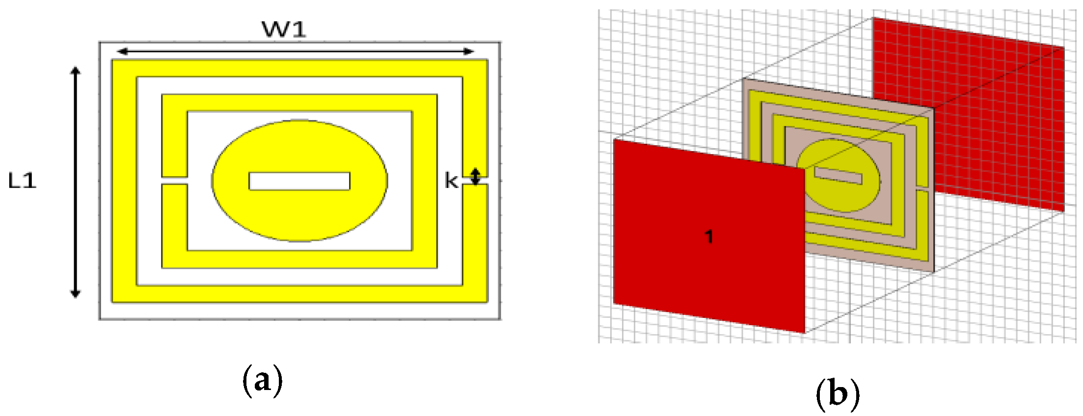
A compact model has been implemented in this work using a polyimide sub-channel width 0.2 mm with a dimension of 36 × 32 mm. The radiating structure is looking like an M-shape and the micro-design model was designed to stimulate the antenna. Complementary split rings are placed beside the feedline to attain metamaterial characteristics in the design [18]. The proposed structure has been presented in Figure 1a,b as well as the dimensional view of metamaterial is also shown in Figure 1c. The insertion of metamaterial structure provides additional good bandwidth characteristics. Figure 2 shows the unit cell of metamaterial structure and port assignment for analysis [19]. The designed structure is combination with a SRR and a circular slot. One type of metamaterial structure is examined as radiating surface on the antenna to improve bandwidth and placed another structure as a frequency selective surface beneath the model for the improvement of gain in this work. The FSS placement and the antenna analysis are presented in the next section with respect to radiation pattern and surface current distribution [20]. The M-Shaped conformal antenna must be constructed to fit the surface on which it will be mounted. This might be a curved or uneven surface, such as the fuselage of an aeroplane or the body of a vehicle. The antenna should be constructed in such a way that it matches the curvature of the surface flawlessly without generating any mechanical or aerodynamic complications. Check that the operational frequency range of the M-Shaped conformal antenna is compatible with the FSS. The FSS may be configured to block or broadcast particular frequency bands, and the antenna’s frequency should not interfere with these bands. Examine the antenna and FSS polarisation. They should be coordinated to maximise performance. Misaligned polarisation may degrade signal strength and efficiency. The existence of the FSS may impact the antenna’s emission pattern and impedance. Depending on the design and material qualities of the FSS, it may induce electromagnetic wave reflection, scattering, or diffraction. During the antenna design process, these impacts should be examined and minimized [21].
W1 is the width of the FSS structure with dimension of 2 mm and L1 is the length of FSS with dimension of 2.5 mm. The gap between split ring in FSS is ‘k’ and its dimension is 0.2 mm. The gap between metamaterial structure in the antenna model is ‘g’ with the dimension of 0.2 mm and the distance between FSS and antenna is ‘D’ with optimized dimension of 1 mm.
Investigating alternate forms or materials for an M-Shaped conformal antenna’s structure, as well as extra capabilities, may lead to increased antenna performance and broader application options. The radiation pattern, impedance, and bandwidth of an antenna may all be affected by its form. You may use simulation tools to experiment with different forms and optimise the geometry to fulfil particular needs like directional radiation or impedance matching. Experimenting with various forms may result in antennas that are efficient across numerous frequency bands. Multi-band abilities, for example, may be provided via fractal-based or meander-line architectures. The dielectric materials used in the antenna’s construction may have an effect on its performance. High-permittivity elements may be utilized to lower the size of the antenna, but low-loss materials can boost efficiency. Add beam-steering capability by employing phased array components or reconfigurable materials. This enables you to control the antenna’s beam direction electrically. When researching new forms, materials, and extra features for M-shaped conformal antennas, rigorous simulations, prototyping, and testing are required to confirm their performance. Consider the individual application needs and limits as well in order to adjust the antenna design properly. Working with professionals in antenna design, materials science, and electromagnetic modelling may help you explore these options more efficiently.
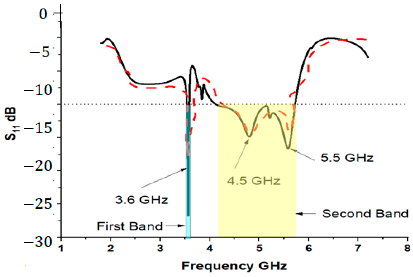
Figure 3 shows the scattering parameter S11 and impulse response curve for the proposed structure with response to the i/p signal applied and it has been found in appreciable way. Antenna resonating at two bands, i.e., 3.6 GHz with considerable BW of 100 MHz & at 5 GHz with bandwidth of 1600 MHz between 4.2–5.8 GHz. A frequent and creative design feature utilized in conformal antenna design is an M-shaped structure, also known as an M-slot or M-shaped slot, especially for obtaining desired performance gains in terms of radiation characteristics, bandwidth, and compactness. In situations where conformal antennas are required, such as on airplanes, missiles, or other curved or unevenly shaped surfaces, this design is very advantageous. In conformal antenna design, the use of an M-shaped structure is significant due to its capacity to improve antenna performance while addressing a number of issues.

3. Results and Analysis

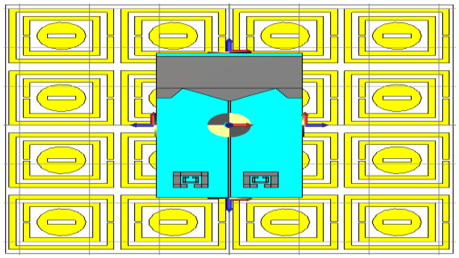
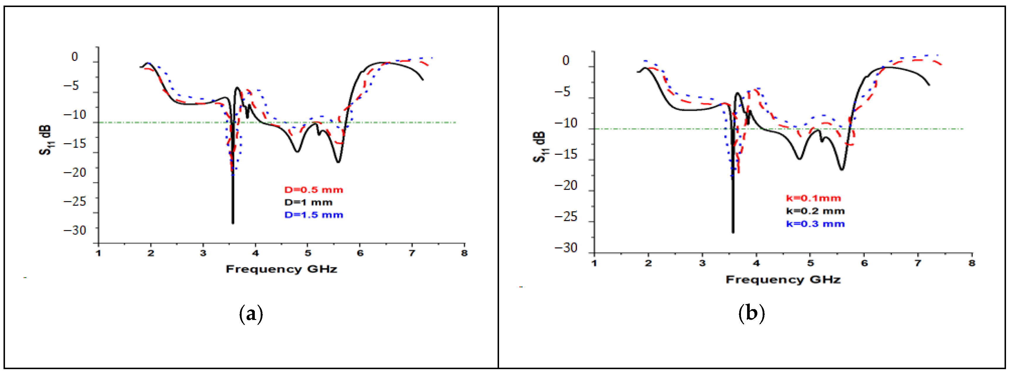
The design of the projected M-structured monopole model, which is laden with a metamaterial and integrated with a frequency selective surface (FSS), can be seen in Figure 3. A 4 × 4 array, serving as the FSS, has been strategically placed beneath the antenna at a distance of 1mm. The reflection coefficient of the model and voltage standing wave ratio (VSWR) following the FSS placement can be observed in Figure 4. The evidence for the applicability of this design in real-world scenarios is clearly provided by the antenna’s multiband features, together with the bandwidth achieved at respective application bands. The impedance bandwidth achieved at the first and second resonant bands are 45% and 52%, respectively. A parametric analysis has been carried out on several characteristics of the antenna, including its dimensional features, the gap between the antenna and the FSS, as well as the dimensional parameters of the FSS itself. Figure 5 demonstrates the effects of dimensional parameter variations on the antenna’s performance when positioned on the FSS. Parameters such as feed line width, the height of the G-model, and the gap among ground planes have been varied within a certain range. This allowed for the determination of optimized dimensional values prior to the prototyping of the antenna model.
The frequency selective surface placed below the antenna at a particular point will disturb the presentation analysis of the designed antenna in accordance with the gain and efficiency. A distance of 0.5 mm to 1.5 mm is considered and analysed the antenna output parameters and the optimized values are presented in Figure 5.
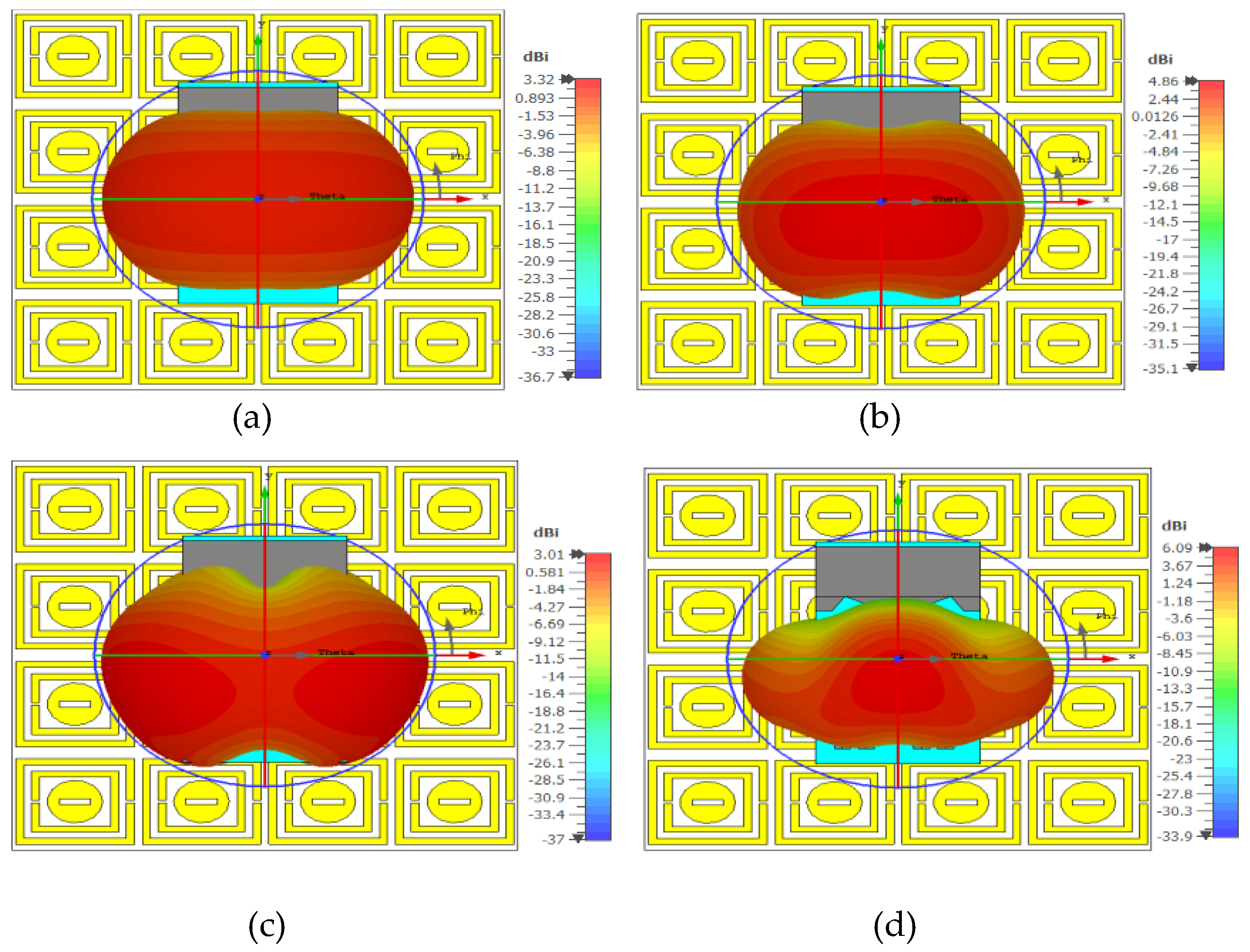
The three-dimensional gain for the designed model at various operating bands were presented in Figure 6. The gain values are varying from 3.01 dB to 6.09 dB between 3.5 to 5.8 GHz. The highest gain is obtained at 5.8 GHz with value more than 6 dB and minimum at 5.5 GHz.
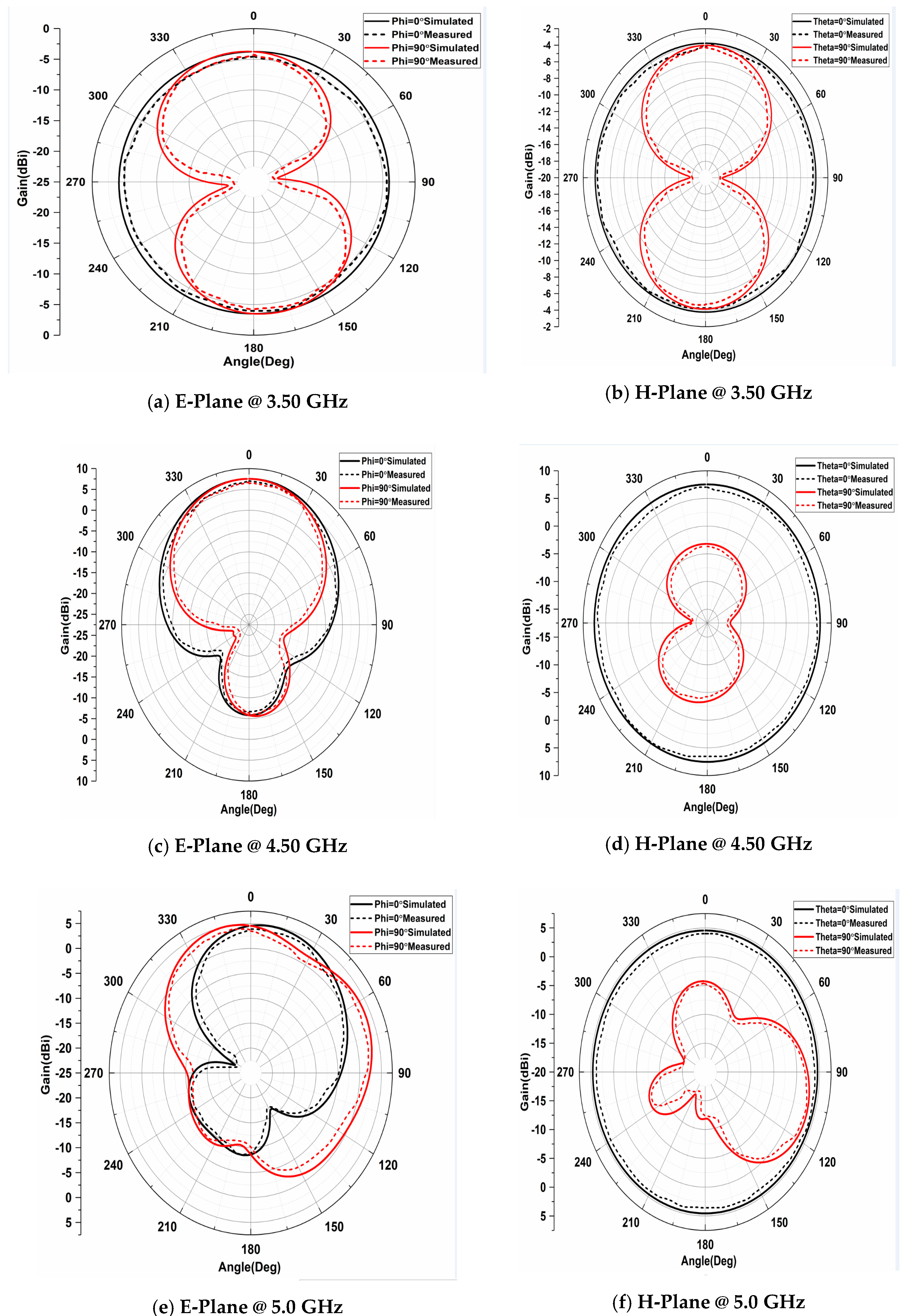
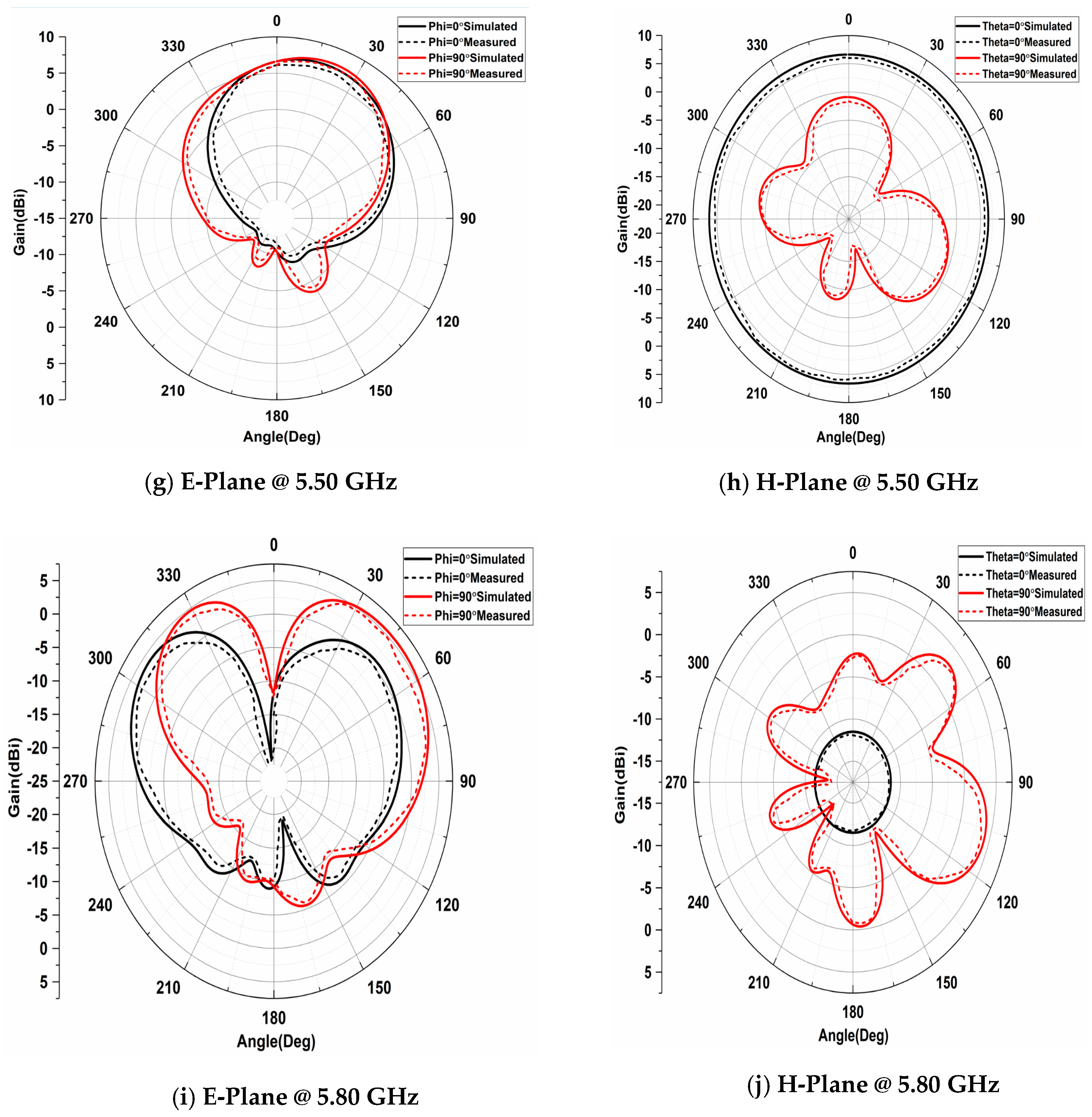
The radiative analysis in polar coordinates is presented in Figure 7. The E as well as H-plane results were both Co and Cross polarizations are analysed from 3.5 to 5.8 GHz at different operating bands. The obtained measured results from the pattern measurement setup are in conjunction with simulation results attained from CST tool.
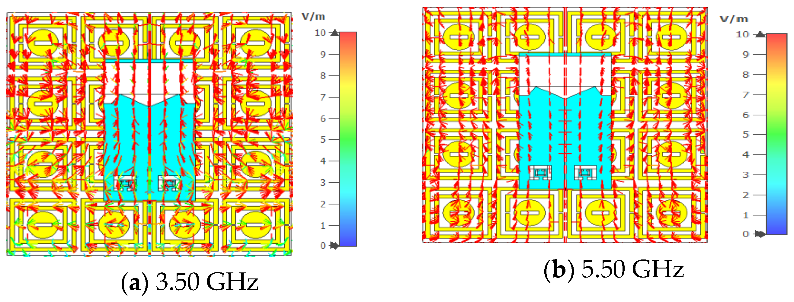
The electric field distribution, magnetic field distribution, and surface apparent current distribution at two operating bands are presented in Figure 8, Figure 9 and Figure 10. The FSS structure beneath the antenna and the field distributions are captured in the combination of both surfaces.
It is essential to validate simulation findings for antenna designs in order to make sure that the performance in practice matches the performance predicted. (Figure 10 and Figure 11).
Normally, you would use a structured setup and approach when measuring an antenna prototype to get excellent matching in the reflection coefficient (S11) and gain. Vector Network Analyzer (VNA), Frequency Sweep, and Gain Measurement were utilized in this antenna prototype. One distinctive element is the use of FSS as a backing framework. FSS components are made to selectively amplify or filter out certain frequency bands. In terms of conformal antenna design, this integration is quite uncommon. Frequency agility and flexibility are provided by the M-shaped conformal design with FSS backing. It enables rapid tuning and adjusting to satisfy particular operating needs. It might be difficult to achieve large impedance bandwidth with conformal antennas. With excellent impedance matching (low reflection coefficient) and a wide impedance bandwidth over the necessary frequency ranges, this design stands out from the competition.
The impedance characteristics of the modelled antenna is analysed for three bending cases of 30, 45, and 60 degrees and presented the same in Figure 12. The shift in the lower band with respect to bending is observed in this experimentation and the upper band is remain constant with no significant variation. In order to accomplish certain frequency filtering or radiation pattern features, a frequency selective surface (FSS) M-shaped antenna combines the principles of a frequency selective surface with an M-shaped construction. Understanding the specific frequency bands associated with these technologies as well as the idea of impedance bandwidth is crucial for designing an antenna that can efficiently cover a variety of wireless communication bands, including Bluetooth, Wi-Fi, ISM (Industrial, Scientific, and Medical), LTE (Long-Term Evolution), 5G, and Wireless LAN.

4. Conclusions

The modelling and investigation of a compact metamaterial loaded mono-pole structure antenna on an elastic substrate is accessible in this research paper. Proposed model resonating at wideband covers several lower band wireless communication applications like Bluetooth, Wireless Fidelity (Wi-Fi), Industrial Scientific and Medical (ISM), Long Term Evolution (LTE), advanced 5G as well as Wireless LAN with impedance bandwidth of 65%. The FSS beneath the antenna structure acts as a reflector and providing additional gain and efficiency improvement of 22% and 12%, respectively. The proposed antenna model can be used in sub-6 GHz band 5G communication lower band applications with surface mountable nature.

Author Contributions

Conceptualization by M.D.L., methodology and validation were done by M.D.L. and S.C., writing as well as review by M.D.L. All authors have read and agreed to the published version of the manuscript.

Funding

This research received no external funding.

Institutional Review Board Statement

Not applicable.

Informed Consent Statement

Not applicable.

Data Availability Statement

The data can be obtained from the corresponding author on request.

Conflicts of Interest

The authors declare no conflicts of interest.

References

  1. Chaitanya, A.V.; Jayaprada, R.; Pavani, M. Circular Monopole Slotted Antenna with FSS for High Gain Applications. ARPN J. Eng. Appl. Sci. 2016, 11, 1–7. [Google Scholar]
  2. Siva Prasad, B.; Mallikarjuna Rao, P.; Madhav, B.T.P. Coplanar wave guide fed fork shaped frequency reconfigurable antenna for LTE, Wi-Fi and WLAN applications. Int. J. Eng. Technol. 2017, 7, 366–375. [Google Scholar] [CrossRef]
  3. Bora, P.; Pardhasaradhi, P.; Madhav, B.T.P. Design of Microstrip Patch Antenna Based on FSS for 5G and WiMAX Applications. J. Nano Electron. Phys. 2021, 13, 1–4. [Google Scholar] [CrossRef] [PubMed]
  4. Srilatha, K.; Madhav, B.T.; Anil Babu, B.; Rishikesh Raj, M.; Somala, T.; Nimmaraju, V.; Rao, M.C. Design and analysis of jeans based wearable monopole antenna with enhanced gain using AMC backing. J. Phys. Conf. Ser. 2021, 1804, 012189. [Google Scholar] [CrossRef]
  5. Madhav, B.T.; Jayantth Reddy, K.; Vani, J.; Priyanka, R.R.; Prudhvi Nadh, B.; Rao, M.C. Concentric ring loaded monopole antenna with AMC backed forwearable applications. J. Phys. Conf. Ser. 2021, 1804, 012191. [Google Scholar] [CrossRef]
  6. Saikumar, K.; Arulanantham, D.; Rajalakshmi, R.; Prabu, R.T.; Kumar, P.S.; Vani, K.S.; Ahammad, S.H.; Eid, M.M.; Rashed, A.N.; Hossain, M.A.; et al. Design and development of surface plasmon polariton resonance four-element triple-band multi-input multioutput systems for LTE/5G applications. Plasmonics 2023, 18, 1949–1958. [Google Scholar] [CrossRef]
  7. Bandhakavi, S.D.; Boddapati, T.M.; Babu, B.A.; Murthy, K.S. A circularly polarized semi-symmetric curvature slot fractal antenna for gain enhancement. J. Eng. Sci. Technol. Rev. 2021, 14, 116–123. [Google Scholar]
  8. Devarapalli, A.B.; Moyra, T.; Madhav, B.T. An FSS based broadband elliptical tree shaped antenna with augmented gain for wireless applications. IETE J. Res. 2022, 1–13. [Google Scholar] [CrossRef]
  9. Badisa, A.; Madhav, B.T.; Srilatha, K.; Rao, M.C.; Das, S. A circularly polarized quad-band wearable textile antenna integrated with triple band AMC Reflector for WBAN applications. Prog. Electromagn. Res. C 2022, 121, 1–18. [Google Scholar] [CrossRef]
  10. Najumunnisa, M.; Sastry, A.S.; Madhav, B.T.; Das, S.; Hussain, N.; Ali, S.S.; Aslam, M. A metamaterial inspired AMC backed dual band antenna for ISM and RFID applications. Sensors 2022, 22, 8065. [Google Scholar] [CrossRef] [PubMed]
  11. Badisa, A.B.; Madhav, B.T.; Srilatha, K.; Chillarige, A.V.; Battula, V.; Garimella, C.V. Design and analysis of AMC reflector integrated flexible and compact vehicular antenna for Communication Application. Radioelectron. Commun. Syst. 2022, 65, 411–419. [Google Scholar] [CrossRef]
  12. Madhav, B.T.P.; Anilkumar, T.; Kotamraju, S.K. Transparent and conformal wheel-shaped fractal antenna for vehicular communication applications. AEU -Int. J. Electron. Commun. 2018, 91, 1–10. [Google Scholar] [CrossRef]
  13. Madhav, B.T.; Venkateswara Rao, M.; Anilkumar, T. Conformal band notched circular monopole antenna loaded with split ring resonator. Wirel. Pers. Commun. 2018, 103, 1965–1976. [Google Scholar] [CrossRef]
  14. Usha Devi, Y.; Rukmini, M.S.; Madhav, B.T. A compact conformal printed dipole antenna for 5G based vehicular communication applications. Prog. Electromagn. Res. C 2018, 85, 191–208. [Google Scholar] [CrossRef]
  15. Devi, Y.U.; Rukmini, M.S.; Madhav, B.T. Liquid crystal polymer based flexible and conformal 5G antenna for vehicular communication. Mater. Res. Express 2018, 6, 016306. [Google Scholar] [CrossRef]
  16. Usha Devi, Y.; Boddapati MT, P.; Kumar, T.A.; Skc, K.; Pardhasaradhi, P. Conformal printed MIMO antenna with DGS for millimetre wave communication applications. Int. J. Electron. Lett. 2019, 8, 329–343. [Google Scholar]
  17. Wu, S.; Zhao, A.; Zhao, Y. Wideband dipole antenna and array based on liquid crystal polymer for 5G applications. In Proceedings of the 2019 IEEE Asia-Pacific Microwave Conference (APMC), Singapore, 10–13 December 2019. [Google Scholar]
  18. Lakrit, S.; Medkour, H.; Das, S.; Madhav, B.T.; Ali, W.A.; Dwivedi, R.P. Design and analysis of integrated Wilkinson power divider-fed conformal high-gain UWB array antenna with band rejection characteristics for WLAN applications. J. Circuits Syst. Comput. 2020, 30, 2150133. [Google Scholar] [CrossRef]
  19. Mangal, J.; Gour, Y. A high gain planar monopole hexagonal circular slotted patch antenna for ultra-wideband and multiple frequency range applications. In Proceedings of the 2021 International Conference on Control, Automation, Power and Signal Processing (CAPS), Jabalpur, India, 10–12 December 2021. [Google Scholar]
  20. Vasimalla, Y.; Pradhan, H.S.; Pandya, R.J.; Saikumar, K.; Anwer, T.M.; Rashed, A.N.; Hossain, M.A. Titanium dioxide-2d nanomaterial based on the surface plasmon resonance (SPR) biosensor performance signature for infected red cells detection. Plasmonics 2023, 18, 1725–1734. [Google Scholar] [CrossRef]
  21. Saikumar, K.; Ahammad, S.H.; Vani, K.S.; Anwer, T.M.; Hadjouni, M.; Menzli, L.J.; Rashed, A.N.; Hossain, M.A. Improvising and enhancing the patterned surface performance of MIMO antenna parameters and emphasizing the efficiency using tampered miniature sizes and layers. Plasmonics 2023, 18, 1771–1786. [Google Scholar] [CrossRef]
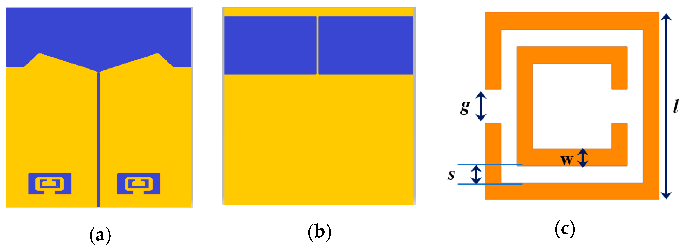
Figure 1. Antenna Design, (a) Top, (b) Bottom, (c) Split Ring.
Engproc 59 00143 g001
Figure 2. Unit Cell Study, (a) Unit Cell Model, (b) Port Excitation.
Engproc 59 00143 g002
Figure 3. Antenna S11 and Response, S11 in dB, and Time domain response.
Engproc 59 00143 g003
Figure 4. Antenna with FSS Structure.
Engproc 59 00143 g004
Figure 5. FSS gap and distance between antenna and FSS, (a) distance, (b) gap.
Engproc 59 00143 g005
Figure 6. 3D-Gain representation, (a) 3.50 GHz, (b) 4.50 GHz, (c) 5.50 GHz, (d) 5.80 GHz.
Engproc 59 00143 g006
Figure 7. Polar plots-based radiation patterns.
Engproc 59 00143 g007aEngproc 59 00143 g007b
Figure 8. Electric Field Analysis Distribution.
Engproc 59 00143 g008
Figure 9. Magnetic Field Analysis Distribution.
Engproc 59 00143 g009
Figure 10. Surface Current Analysis Distribution.
Engproc 59 00143 g010
Figure 11. Bending Angles. (a) 30 deg. (b) 45 deg. (c) 60 deg.
Engproc 59 00143 g011
Figure 12. Impedance variation with conformal angle.
Engproc 59 00143 g012
Disclaimer/Publisher’s Note: The statements, opinions and data contained in all publications are solely those of the individual author(s) and contributor(s) and not of MDPI and/or the editor(s). MDPI and/or the editor(s) disclaim responsibility for any injury to people or property resulting from any ideas, methods, instructions or products referred to in the content.