
Bond Graph Modeling and Simulation of Hybrid Piezo-Flexural-Hydraulic Actuator †


Abstract
1. Introduction
2. Hybrid Piezo-Hydraulic Actuator
2.1. Operating Principle of Hybrid Piezo-Hydraulic Actuator
2.2. Mathematical Modeling of Hybrid Piezo-Hydraulic Actuator
2.2.1. Piezoelectric Stack Actuator
2.2.2. Flexural Displacement Amplifier
3. Bond Graph Modeling
3.1. Bond Graph Modeling of Hybrid Piezo-Hydraulic Actuator
3.2. Bond Graph Modeling of Hybrid Piezo-Hydraulic Actuator
4. Results
5. Conclusions
Author Contributions
Funding
Institutional Review Board Statement
Informed Consent Statement
Data Availability Statement
Conflicts of Interest
References
- Mohith, S.; Muralidhara; Navin Karanth, P.; Kulkarni, S.M.; Upadhya, A.R. Development and Assessment of Large Stroke Piezo-Hydraulic Actuator for Micro Positioning Applications. Precis. Eng. 2021, 67, 324–338. [Google Scholar]
- Mohith, S.; Karanth, P.N.; Kulkarni, S.M. Recent trends in mechanical micropumps and their applications: A review. Mechatronics 2019, 60, 34–55. [Google Scholar] [CrossRef]
- Karanth, P.M.S.N.; Kulkarni, S.M. Performance analysis of valveless micropump with disposable chamber actuated through Amplified Piezo Actuator (APA) for biomedical application. Mechatronics 2020, 67, 102347. [Google Scholar]
- Mohith, S.; Karanth, P.N.; Kulkarni, S.M. Experimental investigation on performance of disposable micropump with retrofit piezo stack actuator for biomedical application. Microsyst. Technol. 2019, 25, 4741–4752. [Google Scholar] [CrossRef]
- Muralidhara, R.R. Displacement characteristics of a piezo actuator-based prototype microactuator with a hydraulic displacement amplification system. J. Mech. Sci. Technol. 2015, 29, 4817–4822. [Google Scholar] [CrossRef]
- Rodriguez-Fortun, J.M.; Orus, J.; Alfonso, J.; Buil, F.; Castellano, J.A. Hysteresis in Piezoelectric Actuators: Modeling and Compensation. IFAC Proc. Vol. 2011, 44, 5237–5242. [Google Scholar] [CrossRef]
- Zhang, Y.; Lu, T.F. Investigation on the Uniform Electrical Field Assumption for Modelling Multi-layer Piezoelectric Actuators. IFAC Proc. Vol. 2011, 44, 5237–5242. [Google Scholar]
- Masson, L.; Civet, Y.; Germano, P.; Perriard, Y. Design of a Generalised Charge-Based Self-Sensing Model for Quasi-Static Piezoelectric Actuators. In Proceedings of the 2017 20th International Conference on Electrical Machines and Systems (ICEMS), Sydney, NSW, Australia, 11–14 August 2017; pp. 1–6. [Google Scholar]
- Ghosh, B.; Jain, R.K.; Majumder, S. Control of Voltage Signal for Piezoelectric Actuator towards Micro Manipulation. In Proceedings of the 2013 International Conference on Communication and Signal Processing, Melmaruvathur, India, 3–5 April 2013; pp. 922–926. [Google Scholar]
- Kim, H.; Najafi, K. An Electrically-Driven, Large-Deflection, High-Force, Micro Piston Hydraulic Actuator Array for Large-Scale Microfluidic Systems. In Proceedings of the 2009 IEEE 22nd International Conference on Micro Electro Mechanical Systems, Sorrento, Italy, 25–29 January 2009; pp. 483–486. [Google Scholar]
- Zhang, Y.; Lu, T.-F. Investigation on the Uniform-Electrical-Field Assumption for Modelling Multi-layer Piezoelectric Actuators. In Proceedings of the 2014 8th Asia Modelling Symposium, Taipei, Taiwan, 23–25 September 2014; pp. 251–254. [Google Scholar]
- Kloub, H. Investigation of Flexural Mechanical Amplifier for the Development of Miniaturized and Large Force Piezoelectric Actuator for Medical Implant Applications, ACTUATOR. In Proceedings of the International Conference and Exhibition on New Actuator Systems and Applications 2021, Online, 17–19 February 2021; pp. 1–4. [Google Scholar]
- Mulling, J.; Usher, T.; Dessent, B.; Palmer, J.; Franzon, P.; Grant, E.; Kingon, A. High Displacement Piezoelectric Actuators: Characterization at High Load with Controlled end Conditions, ISAF 2000. In Proceedings of the 2000 12th IEEE International Symposium on Applications of Ferroelectrics (IEEE Cat. No.00CH37076), Honolulu, HI, USA, 21 July–2 August 2000; Volume 2, pp. 745–748. [Google Scholar]
- Zheng, L.; Gang, Y.Z.; Wu, K.J.; Feng, P.S.; Sheng, L. Research on the Theory and Simulation of Piezo-Hydraulic Actuator. In Proceedings of the 2014 International Conference on Advanced Mechatronic Systems, Kumamoto, Japan, 10–12 August 2014; pp. 156–158. [Google Scholar]
- Chiang, M.-H.; Lee, L.-W.; Huang, K.-S. Development of a Hydraulic-Piezoelectric-Actuator for Hybrid Positioning Control with Large Stroke, High Loading and Sub-Micrometer Accuracy. In Proceedings of the IEEE International Conference on Mechatronics, 2005. ICM’05, Taipei, Taiwan, 10–12 July 2005; pp. 45–49. [Google Scholar]
- Liu, H.; Yu, L. Analytical Method of Fault Detection and Isolation Based on Bond Graph for Electromechanical Actuator. In Proceedings of the 2017 IEEE International Conference on Mechatronics and Automation (ICMA), Takamatsu, Japan, 6–9 August 2017; pp. 393–397. [Google Scholar]
- Touairi, S.; Khouya, Y.; Bahanni, C.; Khaouch, Z.; Mabrouki, M. Mechatronic Control and Modeling of a Piezoelectric Actuator. In Proceedings of the 2019 International Conference on Wireless Technologies, Embedded and Intelligent Systems (WITS), Fez, Morocco, 3–4 April 2019; pp. 1–6. [Google Scholar]
- Premnath, N.; Sanjawadmath, V.; Muthe, S.; Jazui, N. Electro-Hydraulic Actuation System Modeling using Bond Graph Technique. In Proceedings of the 2018 3rd IEEE International Conference on Recent Trends in Electronics, Information & Communication Technology (RTEICT), Bangalore, India, 18–19 May 2018; pp. 2130–2134. [Google Scholar]
- Touairi, S.; Khouya, Y.; Bahanni, C.; Mabrouki, M. Sliding-Mode Control of Piezoelectric Actuator using Bond Graph. In Proceedings of the 2019 5th International Conference on Optimization and Applications (ICOA), Kenitra, Morocco, 25–26 April 2019; pp. 1–7. [Google Scholar]
- Umesh Rai, B.; Umanand, L. Bond graph model of an induction machine with hysteresis nonlinearities. Nonlinear Anal. Hybrid Syst. 2010, 4, 395–405. [Google Scholar] [CrossRef]


| Parameter | Value |
|---|---|
| Chamber diameter | 41.00 mm |
| Chamber depth | 4.00 mm |
| Input piston diameter | 40.00 mm |
| Output piston diameter | 4.50 mm |
| Parameter | Value |
|---|---|
| Mass of piezo-stack actuator, mp | 3.8 g |
| Stiffness of piezo-stack actuator, kp | 50 N/μm |
| Damping of piezo-stack actuator, cp | 150 Ns/m |
| Capacitance of piezo-stack actuator, C | 1.55 μF |
| Electromechanical coupling, d33 | 0.1334 μm/V |
| Stiffness of flexural amplifier along x-axis, ks | 28.903 N/μm |
| Amplification factor for flexural amplifier, A.Ff | 6.39 |
| Amplification factor for hydraulic actuator, A.Fh | 79.02 |
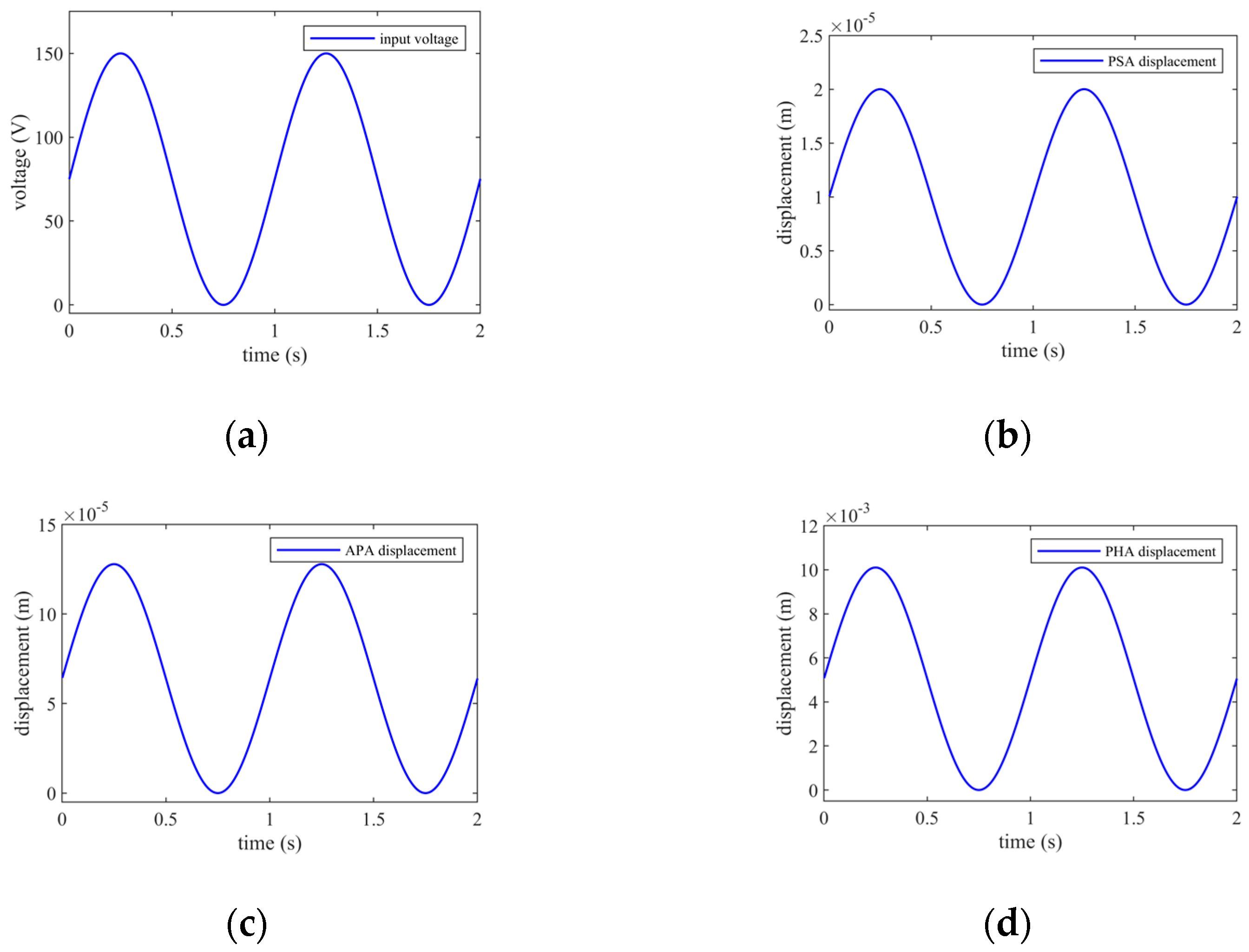
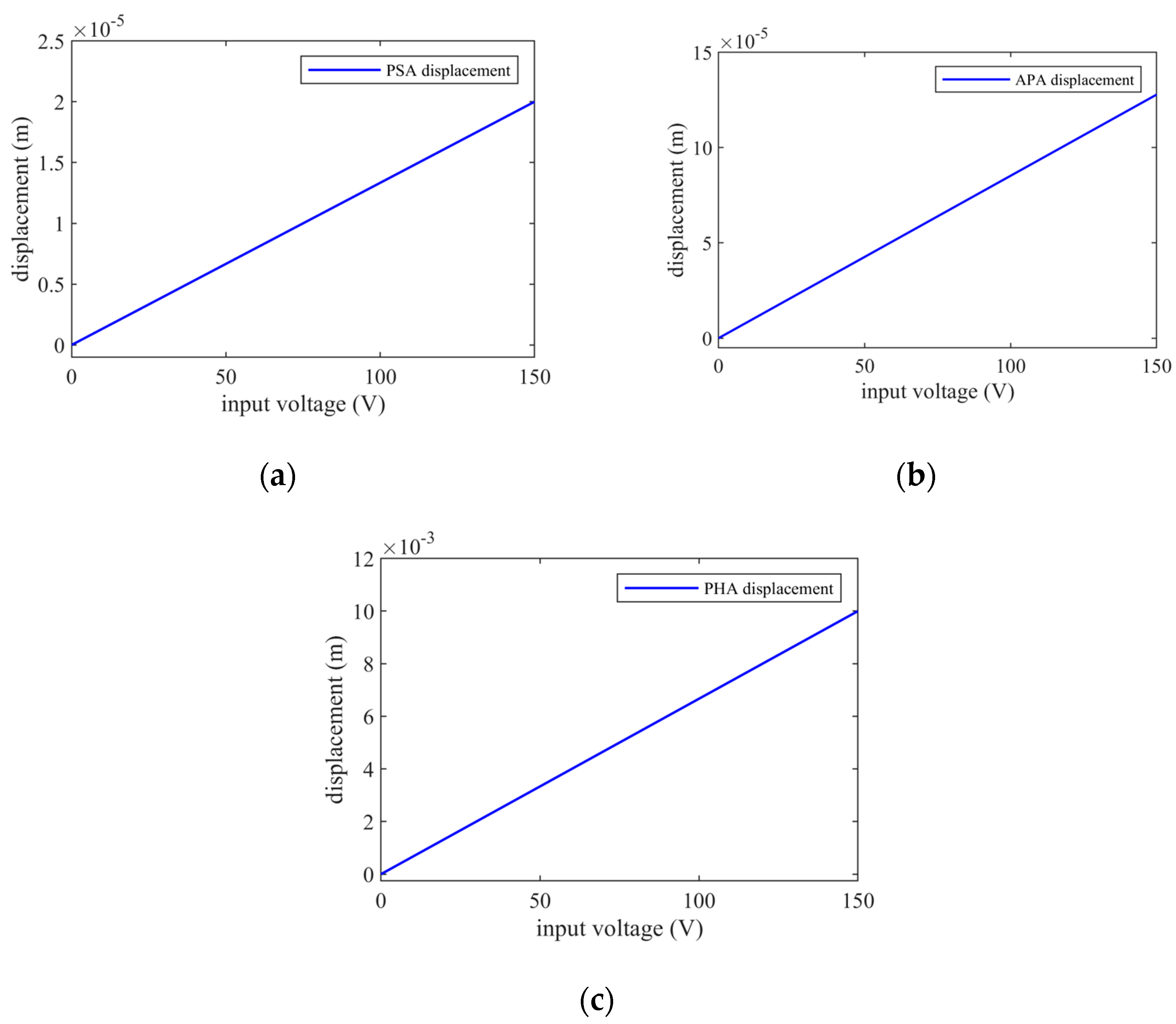
| Parameter | Displacement | Offset | Sensitivity |
|---|---|---|---|
| PSA displacement | 20 μmp−p | 10 μm | 0.1333 μm/V |
| APA displacement | 127 μmp−p | 63.5 μm | 0.8467 μm/V |
| PHA displacement | 1 cmp−p | 0.5 cm | 66.66 μm/V |
Disclaimer/Publisher’s Note: The statements, opinions and data contained in all publications are solely those of the individual author(s) and contributor(s) and not of MDPI and/or the editor(s). MDPI and/or the editor(s) disclaim responsibility for any injury to people or property resulting from any ideas, methods, instructions or products referred to in the content. |
© 2024 by the authors. Licensee MDPI, Basel, Switzerland. This article is an open access article distributed under the terms and conditions of the Creative Commons Attribution (CC BY) license (https://creativecommons.org/licenses/by/4.0/).
Share and Cite
Kelkar, R.; Santhya, M.; Kanchan, M.; Powar, O.S. Bond Graph Modeling and Simulation of Hybrid Piezo-Flexural-Hydraulic Actuator. Eng. Proc. 2023, 59, 202. https://doi.org/10.3390/engproc2023059202
Kelkar R, Santhya M, Kanchan M, Powar OS. Bond Graph Modeling and Simulation of Hybrid Piezo-Flexural-Hydraulic Actuator. Engineering Proceedings. 2023; 59(1):202. https://doi.org/10.3390/engproc2023059202
Chicago/Turabian StyleKelkar, Rudraksha, Mohith Santhya, Mithun Kanchan, and Omkar S. Powar. 2023. "Bond Graph Modeling and Simulation of Hybrid Piezo-Flexural-Hydraulic Actuator" Engineering Proceedings 59, no. 1: 202. https://doi.org/10.3390/engproc2023059202
APA StyleKelkar, R., Santhya, M., Kanchan, M., & Powar, O. S. (2023). Bond Graph Modeling and Simulation of Hybrid Piezo-Flexural-Hydraulic Actuator. Engineering Proceedings, 59(1), 202. https://doi.org/10.3390/engproc2023059202