Proceeding Paper

Design of Rigid-Locking Variable-Angular-Span Welding Fixture †

by
Ganesh Kadam
1,*,
Bharathiseshan Nagarajan
2,
Varadaraj Mirji
2 and
Siddhesh Sawant
2
1
Department of Mechanical Engineering, Bharati Vidyapeeth College of Engineering, Navi Mumbai 400614, Maharashtra, India
2
Department of Mechanical Engineering, SIES Graduate School of Technology, Navi Mumbai 400706, Maharashtra, India
*
Author to whom correspondence should be addressed.
Presented at the 5th International Conference on Innovative Product Design and Intelligent Manufacturing Systems (IPDIMS 2023), Rourkela, India, 6–7 December 2023.
Eng. Proc. 2024, 66(1), 35; https://doi.org/10.3390/engproc2024066035
Published: 22 July 2024

Abstract

:
The manufacture of high-quality products mandates precise positioning in welding, and the same can be achieved through the use of fixtures which facilitate consistency in repetitive welding tasks. Traditional existing practices followed in industries include the use of standard-angle fixtures and are limited to fixed 90° orientations. This limits their usage to components needing joining by welding to be performed at various prescribed angles. Thus, to overcome these challenges and improve welding practices, a low-cost and user-friendly fixture was developed that enabled precise welding at angles other than 90°. This fixture finds wide suitability for outdoor welding applications, manufacturing brackets, angles, and other customized jobs. Its design characteristics include adjustability, lightweight construction, rigidity, and ease of use, thus making it stand out from existing fixtures. The unique features of the fixture enable one to minimize errors, reduce waste and associated costs, and increase productivity, thus leading to higher employee satisfaction and a better reputation for the company. Further, due to the elimination of the need for post-welding follow-up work, manufacturers can produce more products with ease and speed, thus resulting in significant benefits for their business.

1. Introduction

The manufacturing industry is a complex system which necessitates integrating a variety of elements like personnel, machinery, processes, and materials to achieve optimal outcomes. Although numerous manufacturing techniques exist, welding plays a pivotal role in producing engineering components, with a significant proportion of them undergoing welding during their manufacturing cycle. While robotic and automated welding is often employed for the mass production of small welding jobs, high-quality products necessitate the use of precise and accurate welding equipment. However, manual welding is preferred in situations where cost or specific requirements are the primary considerations. For larger jobs or those with varying configurations, manual welding is the most practical option, and fixtures are utilized to ensure accuracy, reduce operator fatigue, and expedite production speed. Fixtures are a critical aspect of the manufacturing industry since they help operators hold components in the right position prior to welding, leading to perfectly configured welded components. The application of fixtures has been a crucial component of many manufacturing operations in the past, and researchers continually explore their potential uses in welding operations. The use of fixtures is essential in ensuring consistent, high-quality welds, optimizing productivity, reducing costs, and improving product quality. Regardless of the welding method employed, fixtures are an indispensable tool in the manufacturing industry.

2. Literature Review

Within the context of the design and use of fixtures in manufacturing, recent works by various researchers can be summarized as follows. Solkar et al. [1] proposed the design of a multi-degree rotating fixture for drilling at 8–15°, which thereby eliminated the need of different fixtures for every specific angle, hence leading to a reduced cost. Daitao [2] designed and fabricated a multi-angle welding fixture for joining bars and pipes with adjustable clamping jaws in the range of 30–180°, and this enabled easy clamping as well as faster welding. Chuong [3] designed a movable welding and automatic cutting fixture for steel pipes, which was found to be beneficial in terms of high performance, easy operation, and low cost of fabrication. Rampur et al. [4] identified problems in the full welding of a concrete mixer’s chassis and proposed a fixture design which eliminated prior damages to the chassis, eliminated the need of an overhead crane, and permitted welding at any angle, facilitating an ergonomic weld position for the welder. Yuvaraj et al. [5] devised a welding fixture for the steering handle of a two-wheeler, which enabled high precision in placing curved surfaces, particularly in mass manufacturing, and achieved that without the use of any robots. Kalase et al. [6] designed a welding fixture which permitted the machining of a stator of different lengths followed by welding, and it was found to be beneficial in terms of reduced costs, decreased non-productive time, minimal material handling, reduced work-in-progress, as well as setup time. Bahadure and Waghmare [7] designed and analysed a fixture for welding a car panel shifting unit entity, which permitted the adjustment of the locating pin in order to prevent interference during the load–unload cycle of the car panel thus preventing damage. Naveen and Girish [8] designed a fixture for welding a rocket motor case’s head end sub-assembly, which helped in achieving a specified tolerance and thus increased work acceptance. Arjun et al. [9] planned and fabricated the welding fixture of a door frame considering the specifications of easy removal after operation, proper clearance, easy accessibility for welding, loading/unloading, and was found to be useful in holding lengthy door frames, rigid and simple in construction, and of lower cost. Reddy et al. [10] developed a fixture facilitating the welding of a nozzle casing assembly taking into consideration the quality, reliability, purging, and damping, and it enabled welding to be performed with negligible distortion, ovality, and other weld defects. Siddesha and Ramegowda [11] designed and analysed a welding fixture for a footrest stand component so as to provide a clamping action with the least distortion and hold the workpiece in proper position during welding operation. Khetani et al. [12] designed, analysed, and optimised a welding fixture for the brake pedal of a tractor and achieved increased efficiency, reduced manual error, improved quality, and reduced production time. Ingale et al. [13] designed and analysed a fixture facilitating the welding of a shell and tube heat exchanger’s inlet header, which led to a reduced welding time and increased dimensional accuracy. Vaishak et al. [14] designed a fixture for a wheel loader’s front chassis welding, which was found beneficial in terms of reduced operator fatigue, reduced cycle time, and less wear of the fixture components. Reddy [15] designed and developed a multipin welding fixture for an EBW machine, which enabled the weld-joining of 10 tubes in one cycle and enabled an increased production and reduced time required in repeated vacuum cycles. Asabe et al. [16] redesigned the existing welding fixture for a casing wear ring, which eliminated the bottlenecks of an older design setup and led to a simplified procedure for operation. Sayambar et al. [17] designed a welding fixture for a brake pedal assembly, which enabled them to weld with the least power and resistance and also helped in reducing the production time as well as improving the weld quality. Arunraja et al. [18] designed and optimised drilling fixture which enabled the elimination of the elastic deformation caused by clamping and the machining force on the workpiece. Ubale et al. [19] designed, analysed, and optimised a welding fixture for automotive and non-automotive components, which led to a material and cost reduction.
After referring to the recent works of the various researchers, it can be concluded that there are many fixtures which have been designed and made for various applications from automobile to heavy and small-scale industries. The design of these fixtures has improved the quality of the weld, positioning, stability, and minimized operation cost. Hence, the usage of fixtures may prove to be beneficial from different perspectives. Nowadays, production orders in industries generally are more inclined towards batch or job-shop production, with the prior being more common for small and medium size components. In view of the same and considering broad manufacturing scenarios, during the manufacture of components, many times, welding operation is the requirement for joining two or multiple parts at specific angles or orientation, which is executed by operators manually, giving rise to errors, weld defects, and increased operation costs. Hence, there is a need for the design and development of fixtures which can be easily located and positioned in confined areas and places, achieving a good quality level and being easy to use and accessible for welding operations. Thus, the present work discusses the design and further development of a special fixture permitting configurations at multiple angles for welding operations and elaborates them in the following sections.

3. Methodology

Through the interpretation of the preceding section, it is well understood that due necessity arises for a unique fixture for welding. This fixture should particularly serve the purpose of joining two components at a specific angle other than 90° or 45°. Precisely locating the workpiece must be possible by incorporating this welding fixture. Additionally, the use of fixtures can also help to speed up the manufacturing process by making it easier to hold and position workpieces, which can increase productivity. If a new welder is not properly trained to position the workpiece or maintain the correct welding technique, it can result in inconsistent or poor-quality welds. This can ultimately lead to the need for rework, which increases costs and can also cause delays in production schedules. There can be various types of defects that can occur in welded joints, including improper fusion, undercut, lap, distortion, warpage, etc. These defects can weaken the joint, decrease the strength and functionality of the finished product and lead to further issues. In the fabrication industry, a good welding fixture plays an important role during the welding process, reducing the likelihood of inaccuracies caused by human error or poor work-holding techniques. Even with skilled and experienced operators, it is difficult to consistently achieve the precise desired weld angle manually. With an overall perspective, a decision was made to design a specialized welding fixture to address the issues that have been discussed above. Furthermore, there was also a requirement to create such a mechanism that would allow for welding at angles other than 90° or 45° in order to meet specific manufacturing needs. Corrosion resistance, load carrying capacity, stress factors, and wear criteria are all important factors to consider when choosing materials for a welding fixture.
Considering all the above aspects, a special welding fixture was proposed to be designed. Through intensive technical discussions and brainstorming, a fixture design was finally arrived at, and its model was generated in CAD. Figure 1 displays the individual parts that make up the fixture, whilst Figure 2 reveals the assembled condition of the fixture. The major elements making up the welding fixture comprised a vertical frame, a horizontal frame, switchable magnets, a link, a protractor, and a pin. The vertical and horizontal frames were made up of an aluminium alloy as it had good strength, high workability, and also had corrosion-resistance properties. The link, protractor, and pin were made up of mild steel because of its durability and shock resistance. The link was used to connect the vertical and horizontal frame with each other, and it also supported the protractor. A protractor was attached to the right end of the link. The protractor had holes at an interval of 20°, which could be used to weld the two metal sheet at an angle (90 − x)°, where x is that angle at which the hole in the horizontal frame coincided with the hole in the protractor. A pin was used to connect the link to the vertical and horizontal frames. Also, the vertical frame could be further used to weld the two metal sheets at an angle of 90°. Magnets can provide a strong and secure hold on the workpiece while still allowing for easy repositioning and adjustments. Additionally, using magnets can eliminate the need for clamps and other mechanical devices, which can simplify the design of the fixture and make it easier to use. Thus, a solution to the problem of holding the workpiece in place during welding at specific angles is the use of switchable magnets. Hence, magnets can be turned on and off as needed, allowing the arms of the fixture to be magnetic or non-magnetic depending on the requirements of the welding operation. A pin was used to connect the link to the vertical and horizontal frames.

4. Results and Discussion

One of the main advantages of a welding fixture is its precision, as it allows for accurate and consistent connections to be made at any angle. In many cases, there is a need to weld plates or metal sheets relatively oriented at 45° or 90° angles. In the majority of cases, the parts are manually aligned when such welding is performed. For that, a standard fixed-orientation welding fixture as shown in Figure 3 is used in practice. As the industry demands more complex and precise components, the need for accurate and reliable welding at angles other than 90° or 45° has become seemingly important. There are a variety of different types of high-quality fixtures currently used in the industry, such as hydraulic, pneumatic, and standard-angle fixtures. These fixtures are designed specifically for use in a particular location or setting and may not be suitable for use in other environments. Using different types of fixtures or welding equipment that are better suited to specific conditions may be necessary when welding needs to be performed in a variety of different locations or settings. This necessitates the use of a specialized fixture that may accommodate different weld angles and can be utilized for welding off-site as well. Thus, there is a need for a versatile fixture that can accommodate a range of different welding angles and can also be easily transported and used in different locations outside of a workshop or factory setting, if need arises. Hence, the special welding fixture which was designed as elaborated in the previous section can be a useful solution in these situations (see Figure 2).
Considering the unique fixture’s structural design features, it can be deduced that desired angles other than 90° and 45° for welding are easily possible through setting up the fixture configuration accordingly. For this, we need to set the horizontal and vertical frames so as to achieve the desired welding angle geometry. Initially the magnets of both the horizontal and vertical frames are kept in off mode with the use of their respective knobs. Then, the vertical frame and horizontal frame are adjusted by rotation with respect to the link so as to get the desired welding angle. Then, they are locked in position by inserting the pin matching the recess in the link and protractor element. The frame is rotated in context to the link by an angle of 90 − x° where x is the required configuration angle. At that time, the two components requiring joining using welding need to be brought closer with each other. Component 1, i.e., sheet 1, is initially located and aligned using the flat surface on the vertical frame. Then, the switchable magnet of the vertical frame can be turned on so that sheet 1 becomes constrained in its position. At that point, component 2, i.e., sheet 2, is brought in conjunction with the horizontal frame and aligned as well as located so as to obtain the correct edge-to-edge configuration with respect to sheet 1. After this, the switchable magnet of the horizontal frame is turned on so that sheet 2 also becomes constrained in position. Hence, the fixture elements and the components to be welded are all properly locked so as to obtain the overall desired welding configuration. Thus, an operator can perform the welding easily and correctly without worrying about the loss of alignment of the components being welded. Further, in case the welding needs to be completed on components at 90° only, then the flat surfaces of the vertical frame alone as well as the switchable magnets are sufficient enough for configuring the components relative to each other. After the welding process is complete, the deactivation of the switchable magnets is performed. An effortless separation of weld-joined components from the fixture is possible, thus making the latter available for use in the next production cycle. The specially designed fixture supports welding at different angles ranging from 0° to 90°, and 45° in particular, at high levels of accuracy and precision. An illustration of components needing welding at a 30° orientation and the corresponding fixture configuration is showcased as an example in Figure 4.
Further investigation revealed that the specially built welding fixture was made of materials that provided sufficient strength to brace both components undergoing welding as well as the fixture’s self-structure. Its peculiar design, material configuration, and lightweight construction made it easy to handle. This also permitted it to be transported and used at off-site locations as well. The locking arrangement with the aid of pins gave the fixture high rigidity when locked, and thus facilitated the robust handling by the operator even under severe conditions. Even the use of switchable magnets permitted effortless clamping and unclamping, but with good interfacial contact and location of components. The materials selected for the welding fixture were corrosion- and wear-resistant, resulting in a longer lifespan and reduced repair costs. Further, the materials chosen for the fixture also had shock-absorbing and damping properties, which helped to reduce the impact of vibrations during use. Overall, the designed fixture complied with ergonomic aspects from an operator’s point of view as well as with quality standards from a welding point of view.
Additionally, a comparative analysis was conducted so as to check the cost and error component for different welding modes. Figure 5 shows the correlation between cost and error for welding under a manual mode and that through the use of a standard fixture and the special fixture. It can be seen that manual welding obviously had the lowest cost as it is performed without a fixture and is simply reliant on the operator. The cost of the operator can be considered to be minimal. However, a large of amount of welding error will occur as the welding is subjected to the skills of operators. Even if highly skilled operators are employed, the error can only be minimised to some extent, as the process is affected by various factors like operator fatigue, no. of components, shifts, etc. Contrary to this, the use of standard fixtures enables one to lower the welding errors in contrast to the manual mode, as the operator is relieved from the repetitive task of the manual location–holding–positioning–adjusting of components to be welded. Similarly, the special welding fixture is also beneficial in terms of reducing errors. Since fixtures involve the additional cost of fabricating them, their usage carries a larger cost component than that for manual welding. However, in the long run, the cost of these fixtures is recovered by considering the vast number of components being welded. Thus, the use of welding fixtures and that of the special welding fixture prove to be beneficial in terms of cost–error component.

5. Conclusions

Upon conducting an in-depth analysis of the specialized fixture, several salient findings emerged:
  • The fixture’s intricate configuration enabled the expeditious positioning, locating, and clamping of workpieces during welding, thus decreasing the overall time required for welding operation.
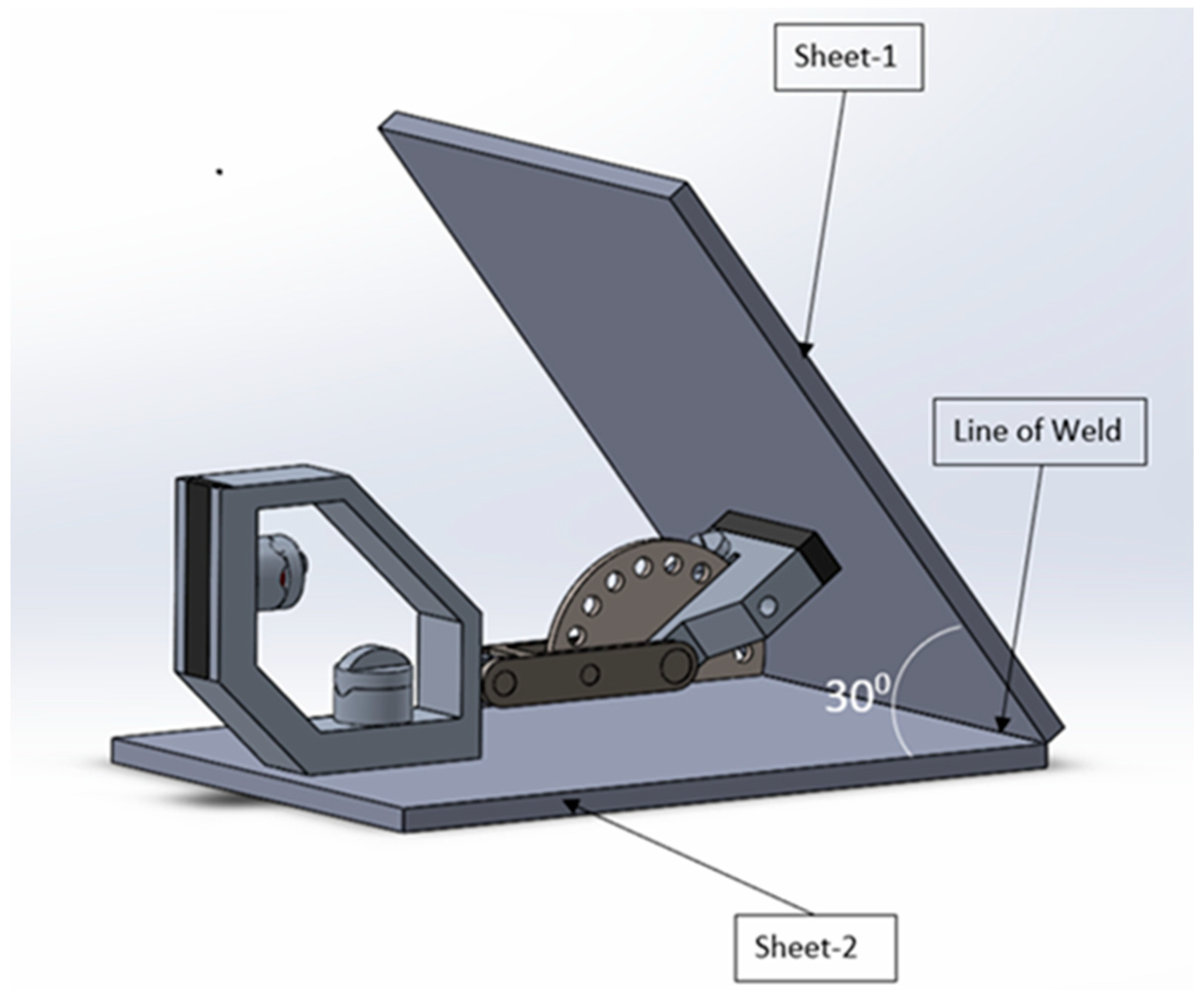
  • The bespoke fixture allowed the components to be welded over a broad spectrum of angles, ranging from 0° to 90°, thereby superseding conventional fixtures that are confined to fixed angles of either 45° or 90°.
  • The fixture’s structural design and material selection synergistically produced a premium-quality product that exhibited superior strength, rigidity, wear resistance, a light weight, and operational ease, all of which rendered it more dependable than its counterparts.
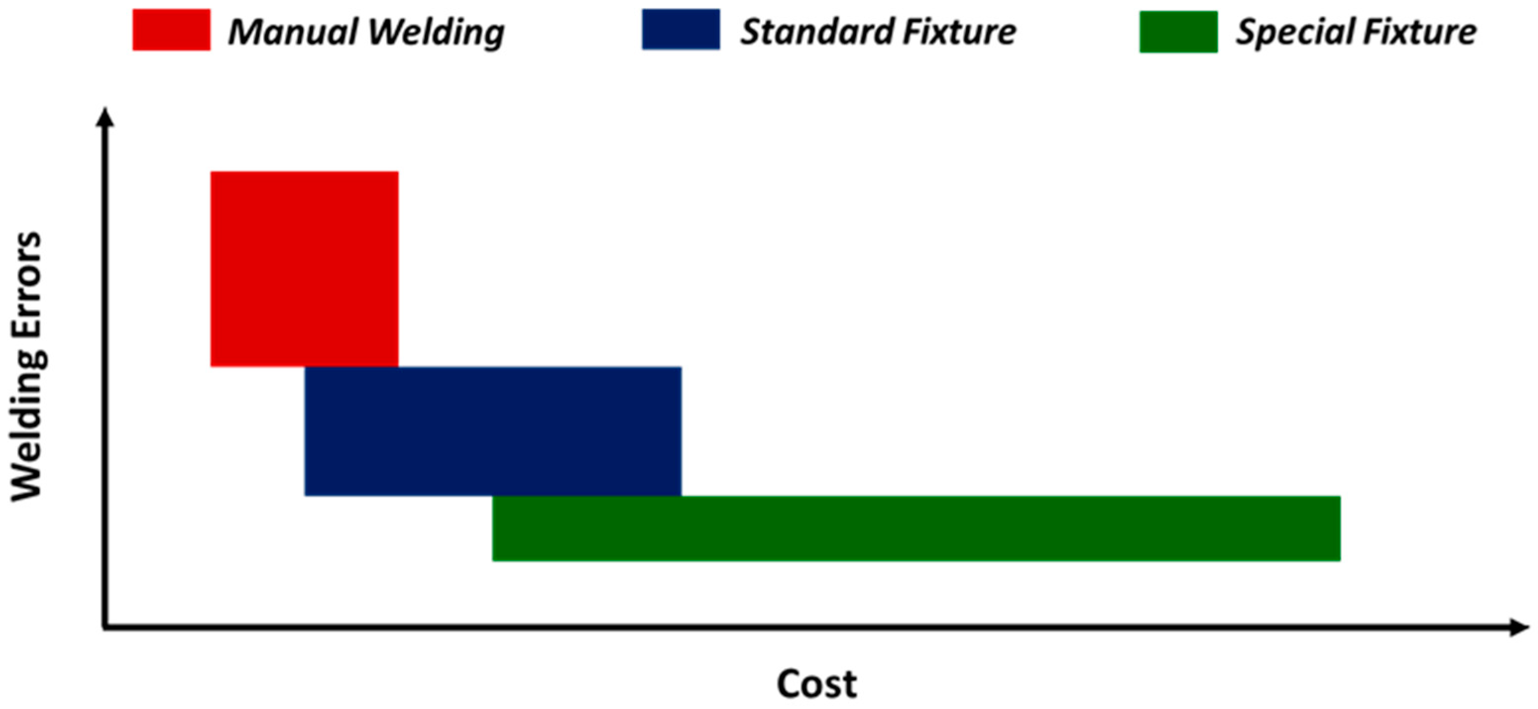
  • The utilization of the designed fixture may prove to be immensely efficacious in mitigating welding errors, particularly when juxtaposed with standard fixtures or manual welding practices bereft of any fixtures.
  • The adoption of the custom-made fixture for welding could engender a multitude of benefits, including an upswing in the manufactured components’ quality, an augmentation in production velocity, cutbacks in rework or scrap, and mitigation of operator fatigue, thereby rendering it highly recommended for widespread implementation in the manufacturing industry.

6. Future Scope

The present fixture was designed to permit the welding of two components at desired angle. It no doubt overcame the limitations of standard welding fixtures meant for fixed-angle welding. However, there is still room for further exploration in the domain. A fixture may be designed so as to permit welding configurations involving more than two components at desired orientations. Additionally, work study, method study, and time study techniques may be incorporated to understand the efficacy of the designed fixtures and then improvise the same as deemed necessary.

Author Contributions

Conceptualization, G.K.; methodology, B.N., V.M. and S.S.; investigation, B.N., V.M. and S.S.; resources, G.K.; writing—original draft preparation, B.N., V.M. and S.S.; writing—review and editing, G.K.; supervision, G.K.; project administration, G.K. All authors have read and agreed to the published version of the manuscript.

Funding

This research received no external funding.

Institutional Review Board Statement

Not applicable.

Informed Consent Statement

Not applicable.

Data Availability Statement

Data are contained within the article.

Conflicts of Interest

The authors declare no conflicts of interest.

References

  1. Solkar, S.J.; Dabhilkar, H.J.; Khedekar, S.S.; More, A.D.; Raut, A.S. Design and Manufacturing of Multi-Degree Rotation of Fixture for Drilling Operation. Int. J. Sci. Adv. Res. Technol. 2018, 4, 116–118. [Google Scholar]
  2. Daitao, E.A. Multi-Angle Welding Jig. Am. Int. J. Contemp. Res. 2019, 9, 39–47. [Google Scholar] [CrossRef]
  3. Chuong, N.V. Improve the Productivity of Welding and Cutting Steel Pipe by using A New Fixture. Int. J. Eng. Res. Technol. 2018, 7, 209–213. [Google Scholar]
  4. Rampur, R.; Yalagi, S.; Venkatesh, M.; Sathishkumar, G. Fixture Design for Self Loading Concrete Mixer’s Chassis Full Welding. Int. J. Eng. Res. Technol. 2018, 3, 1–4. [Google Scholar]
  5. Yuvaraj, M.; Karthick, H.; Gopalakrishanan, V.; Louis, S.W. Design, fabrications and analysis of welding fixture having higher accuracy without using robots. Int. J. Chem. Sci. 2016, 14, 1–8. [Google Scholar]
  6. Kalase, R.S.; Patole, K.; Palaskar, K.; Palaskar, V.; Sabale, A. Design and Development of Stator Stamping Welding Fixture. Int. J. Res. Appl. Sci. Eng. Technol. 2018, 6, 3987–3990. [Google Scholar] [CrossRef]
  7. Bahadure, D.R.; Waghmare, S.N. Design and Analysis of Jig and Welding Fixture for Car Panel to Shift the Locate Pin. Int. J. Innov. Eng. Sci. 2020, 5, 7. [Google Scholar] [CrossRef]
  8. Naveen, A.M.; Girish, V.A. Design of Welding Fixture for Head End Sub-Assembly of Motor Case. Int. J. Sci. Technol. Res. 2014, 3, 276–284. [Google Scholar]
  9. Arjun, C.A.; Vishal, S.K.; Hussain, W.; Ganapathi, P.B.; Hameed, S.; Anand, A.; Sivasubramanian, A.; Arunkumar, G. Design and Fabrication of Welding Fixture for a Single Doorframe. Int. J. Sci. Res. 2014, 3, 166–168. [Google Scholar]
  10. Reddy, C.A.K.; Soni, J.S.; Reddy, N.K.; Harish, P.M.; Teja, V.P.; Gnaneshwar, C. Design Aspects of Welding Fixture for Nozzle Casing Assembly by TIG Welding. Int. J. Eng. Comput. Res. Technol. 2019, 4, 6–12. [Google Scholar]
  11. Siddesha, K.; Ramegowda, D. Design of a Welding Fixture and Analysis for the Footrest Stand Component. Int. J. Eng. Res. Technol. 2015, 4, 995–998. [Google Scholar] [CrossRef]
  12. Khetani, K.; Shah, J.; Patel, V.; Prajapati, C.; Bhaskar, R.V. Design and Thermal Stress Analysis of Welding Fixture of a Brake Pedal. Int. J. Recent Technol. Mech. Electr. Eng. 2015, 2, 29–32. [Google Scholar]
  13. Ingale, Y.; Rade, K.; Bhalerao, N.; Sutar, K. Design and Analysis of Welding Fixture for Inlet Header of Shell and Tube Heat Exchanger. Int. J. Eng. Res. Gen. Sci. 2016, 4, 432–438. [Google Scholar]
  14. Vaishak, B.M.; Sudeep, N.S.; Naveenakrishna, P.V. Design and Analysis of Robot Full Welding Fixture for Front Chassis of Wheel Loader. Int. J. Eng. Trends Technol. 2016, 1, 29–33. [Google Scholar]
  15. Reddy, K.S. Design and Development of Multi Pin Welding Fixture for Electron Beam Welding. Int. J. Curr. Eng. Technol. 2016, 6, 1199–1203. [Google Scholar]
  16. Asabe, S.; Chitnis, R.; Kulkarni, A.; Deshapande, A. Holding and Welding Fixture for Casing Wear Ring. Int. J. Sci. Adv. Res. Technol. 2021, 7, 32–34. [Google Scholar]
  17. Sayambar, A.S.; Hapse, A.S.; Karad, K.S.; Berad, S.S. Design of brake pedal assembly. Int. J. Adv. Res. Innov. Ideas Educ. 2018, 4, 1223–1231. [Google Scholar]
  18. Arunraja, K.M.; Selvakumar, S.; Muthukrishnan, R. Desing and Optimization of Optimal Fixture Layout for Drilling Operation. Int. J. Eng. Res. Technol. 2017, 5, 1–3. [Google Scholar]
  19. Ubale, S.K.; Lomte, S.V.; Kshirsagar, A. Analysis and Optimization of Fixture for the Welding of Automotive and Non-Automotive Components. Int. J. Adv. Res. Ideas Innov. Technol. 2017, 3, 578–583. [Google Scholar]
Figure 1. Family of components of the welding fixture.
Engproc 66 00035 g001
Figure 2. Welding fixture designed for special reconfigurability.
Engproc 66 00035 g002
Figure 3. Standard fixed-orientation welding fixture.
Engproc 66 00035 g003
Figure 4. Orientation of a fixture while welding two metal sheets at an angle of 30°.
Engproc 66 00035 g004
Figure 5. Comparative spectrum of cost vs. error for different welding modes.
Engproc 66 00035 g005
Disclaimer/Publisher’s Note: The statements, opinions and data contained in all publications are solely those of the individual author(s) and contributor(s) and not of MDPI and/or the editor(s). MDPI and/or the editor(s) disclaim responsibility for any injury to people or property resulting from any ideas, methods, instructions or products referred to in the content.

