Proceeding Paper

Contributions to Leak and Air Pocket Detection Using Transient Pressure Signals †

1
CERIS-Civil Engineering Research and Innovation for Sustainability, Instituto Superior Técnico, Universidade de Lisboa, Av. Rovisco Pais 1, 1049-001 Lisboa, Portugal
2
Department of Water Management, Faculty of Civil Engineering and Geosciences, Delft University of Technology, 2628 CD Delft, The Netherlands
*
Author to whom correspondence should be addressed.
Presented at the 3rd International Joint Conference on Water Distribution Systems Analysis & Computing and Control for the Water Industry (WDSA/CCWI 2024), Ferrara, Italy, 1–4 July 2024.
Eng. Proc. 2024, 69(1), 139; https://doi.org/10.3390/engproc2024069139
Published: 14 September 2024

Abstract

:
This study presents insights into how existing faults in pipe systems, like leaks and air pockets, modify transient pressure waves in terms of shape, damping, and phase shift, based on experimental tests conducted at the Hydraulics Laboratory of the Instituto Superior Técnico. Leaks have a major effect on pressure wave damping and shape that increases with the leak size; however, they also preserve the wave phase. The air pocket effect strongly depends on the air pocket size and location, tending to increase wave damping and delay. Also, there is an air pocket volume that leads to the maximum pressures being higher than Joukowsky’s overpressure.

1. Introduction

Water distribution networks inevitably undergo a degradation process, leading to the occurrence of faults, such as water leaks and pipe blockages [1]. These considerably change the pressure wave signal upon a transient event and possibly lead to a pipe burst depending on the severity of the event. The effect of leaks has been analyzed in the framework of inverse transient analysis to detect leaks in pipe systems by Covas [2]. Leaks in pipes have been extensively researched over the past decades due to their impact on water losses as well as on energy losses in water treatment and pumping. Studies have been developed with field data to detect leaks in systems with signal analysis with promising results. However, effective methods to reliably detect different types of pipe faults, like leaks, blockages, and air pockets, based on the analysis of transient pressure wave signals are still under investigation. Pipe blockages have been more recently studied with a few contributions, but their consequences are still uncertain given the reflections of the pressure wave over time due to the physical obstruction of the blockage. Other faults are air pockets, which can be within the flow (‘in-line’) or can remain in dead-ends and devices in the network (‘off-line’), causing pressure variations higher than initially expected [3,4]. The existence of air in the pipes is inevitable, but its amount must be controlled using air-release devices.
Yet, most studies use flow time series to detect anomalous events in water distribution networks, e.g., Loureiro et al. [5]. The current paper focuses on the analysis and discussion of the effect of leaks and air pockets in transient pressure wave signals. This study analyses the transient pressure features in simple pipe setups considering different types, sizes, and locations of faults.

2. Experimental Facilities

Two experimental pipe rigs assembled at the Laboratory of Hydraulics, Water Resources and Environment of the Instituto Superior Técnico in Lisbon were used to conduct this research. Both rigs have similar reservoir–pipe–valve configurations and include copper pipes with an inner diameter of 20 mm and a wall thickness of 1 mm. The difference in the pipe facilities is that one is a 15 m straight and horizontal pipe, whereas the other is a rising pipe-coil with 100 m, which can have some ‘breathing effect’ [6]. At the upstream end of both systems, there is a centrifugal pump and a tank with a capacity of 0.1 m3. Immediately downstream of the pumps, a hydropneumatic vessel with 60 L is installed to simulate a reservoir and to stabilize the inlet pressures. At the downstream end of the system, a pneumatically actuated valve is installed to generate transient events, and the flow rate is controlled with a manual valve. Both rigs are equipped with electromagnetic flowmeters with a maximum flow rate of 2000 L.h−1 with a full-scale accuracy of 0.25% and pressure transducers with a measuring range of 0–25 bar absolute pressures and a full-scale accuracy of 0.5%. The flowmeters are only used to determine the initial steady-state flow rate, and pressure measurements are taken with a frequency of 4 kHz, high enough to describe analyzed transient phenomena [7].

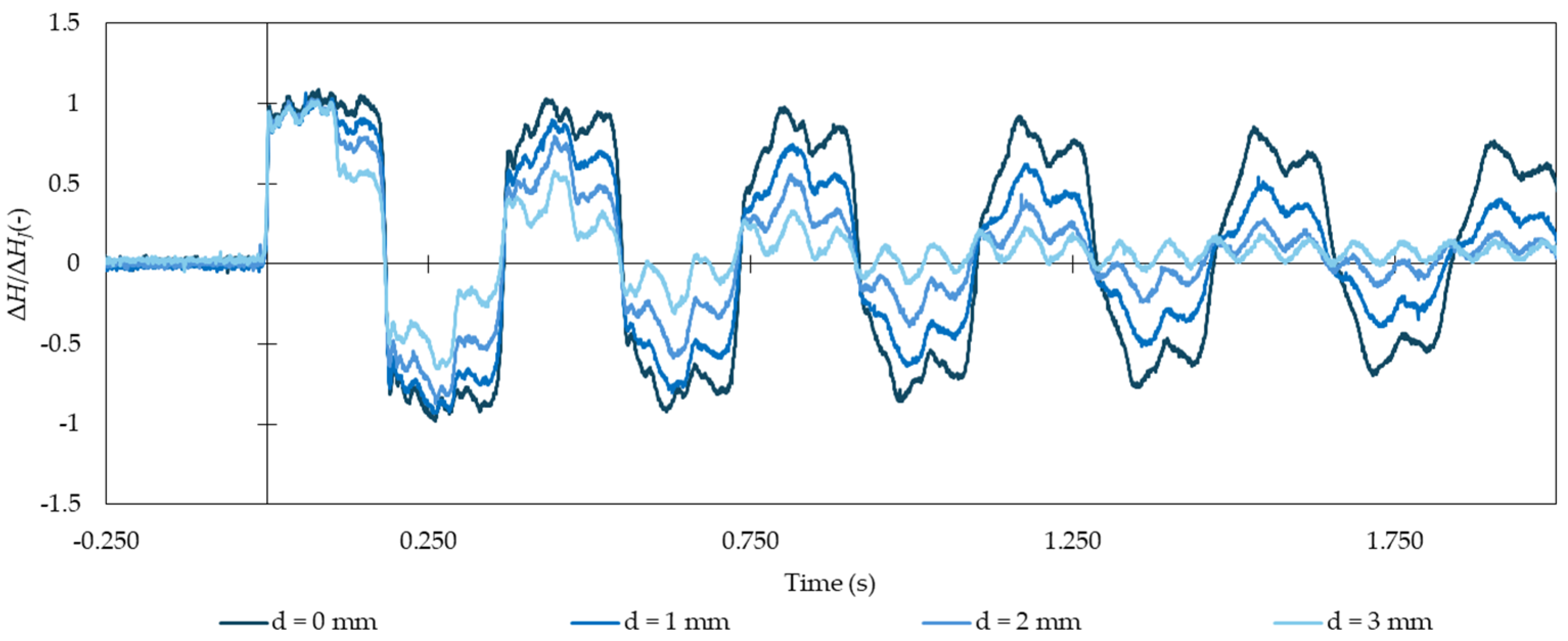
3. Effect of Leaks in the Pressure Signal

Experimental tests with leaks were carried out in the rising coiled facility, with the leak being installed roughly at the mid-length of the system, at 54 m from the downstream fast closure valve. Leaks were modelled by having different-sized orifices in the side discharge valve with diameters d = 0.0 (no leak), 1.0, 2.0, and 3.0 mm. The leak flow rate increases with the orifice diameter, and, since the upstream pressure is relatively constant, the pressure variations for the leak can be considered constant throughout the running steady-state flow rates. Thus, the leak flow rate was measured for each orifice size: QF = 0.015, 0.062, and 0.139 L.s−1. Each of these orifices was tested for a wide range of initial steady-state flow rates at the upstream end, Q0 = 50, 130, 210, 290, and 370 L.h−1.
The pressure signal for Q0 = 210 L.h−1 is presented in Figure 1, where ΔH is the pressure difference between the measured and the steady state pressure and ΔHJ is the pressure variation estimated by the Joukowsky formulation, ΔHJ = aU0/g, being a the pressure wave celerity, U0 is the steady state mean velocity in the pipe, and g is the gravitational acceleration. The observed pressure drop due to the leak considerably increases as the leak flow rate increases, to the point where large pressure variations are only observed during the first three periods of time. After that time, the pressure variations are relatively small (+/− 15% ΔHJ), being the remaining variations due to the fluid–structure interaction of the pipe coil.

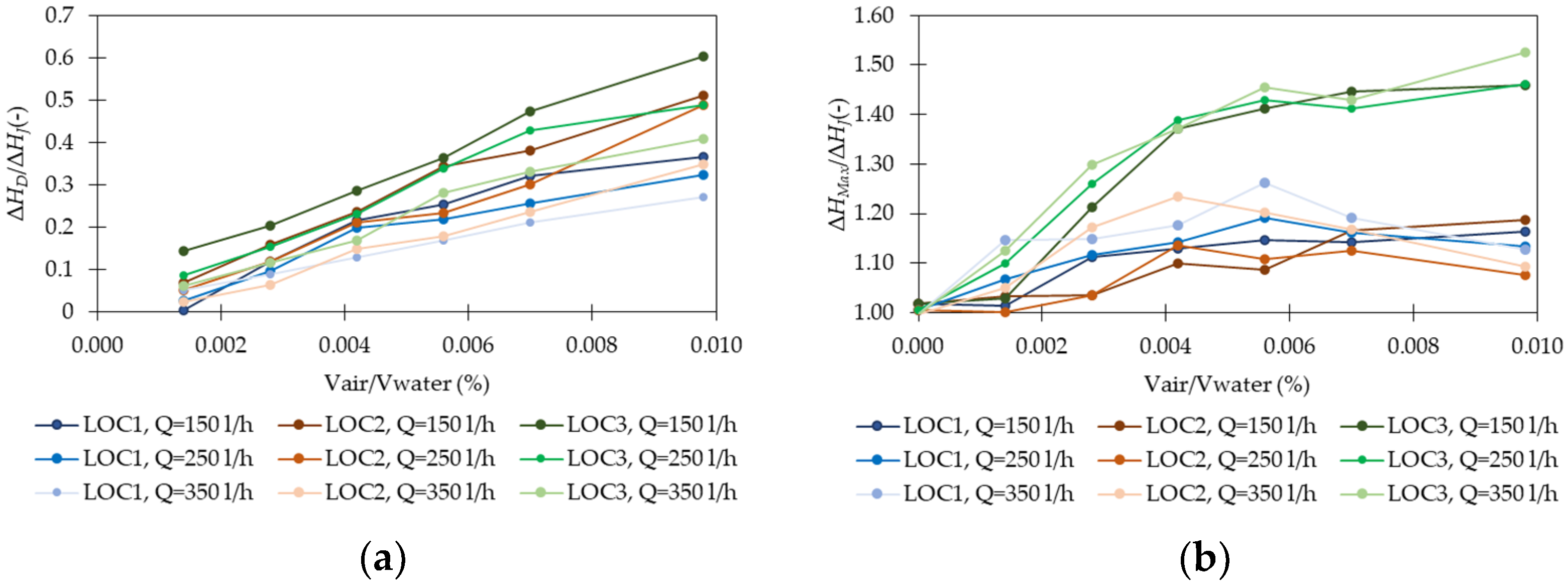
4. Effect of Air Pockets in the Pressure Signal

The straight pipe is used to assess the influence of the entrapped air pocket in the pressure signal. An acrylic device has been installed ‘off-line’ in the pipe to simulate an entrapped air pocket. The tested flow rates vary between 50 and 450 L.h−1, being the tested air pocket sizes presented in Table 1. Two experimental sets of tests were carried out, the first focusing on how the air pocket evolves regarding pressure drop, pressure amplitude, wave damping, and wave phase shift, and the second focusing on the influence of the air pocket position in the previously identified features. The air pocket is positioned, X, at a length of 7.855 m (X/L = 52.4%) from the downstream valve for Set I, whereas it is installed at 2.04 m (LOC1, X/L = 13.6%), 7.855 (LOC2, X/L = 52.4%), and 10.265 m (LOC3, X/L = 68.4%) from the downstream valve for Set II. Increasing air pocket volumes in the same location generates higher pressure drops, increases the wave damping, promotes energy dissipation in the air pocket depending on whether the air-water interface remains intact or not, and further increases the wave shift, reducing the pressure wave frequency. The pressure amplitude is shown to increase from no air volume to a volume Vair/Vwater (%) ratio of 0.003%, decreasing from that point on for the tested system [8].
Tests with the different air pocket locations and sizes show the closer the entrapped air pocket is to the closing valve, the less accentuated the pressure drop in the first period (cf. Figure 2). The pressure wave reaches the air pocket sooner, allowing the air to accumulate some of the energy travelling in the system, that will not travel in the form of momentum in the pipe. The flow rate has some influence on the pressure, drop since the air-water interface remains stable when the pressure variation is smaller. The pressure variations were previously observed to increase up to 25% of the Joukowsky estimate. When the air pocket moves towards the upstream tank, the pressure variations increase from 25% to up to 45% for the largest air pockets and lower air pockets. This occurs because the pipe length between the air pocket and the downstream valve is pressurizing as the pressure wave has not reached the tank yet. The pressure wave shift also occurs as the air volume in the pipe increases, but the shift is more accentuated when the air pocket is closer to the closing valve than to the upstream tank.

5. Conclusions

Several transient tests were carried out for different combinations of air pocket and leak locations, sizes, and initial flow rates. Collected transient pressure-head data were analyzed and the effect of these anomalies on the transient pressure signal was discussed and correlated with their location and size. These analyses are useful to understand the effect of the initial flow rates and the initial anomaly sizes and locations in transient pressure features, such as the maximum and minimum pressure variations, the wave damping, and the wave phase shift. This study is a step forward in understanding the underlying phenomena and an essential step toward the identification and characterization of anomalies in water pipes.

Author Contributions

Conceptualization, D.C., M.C., J.P.F. and H.R.; methodology, D.C., M.C., J.P.F. and H.R.; validation, D.C., M.C., J.P.F. and H.R.; formal analysis, D.C., M.C., J.P.F. and H.R.; investigation, M.C. and J.P.F.; data curation, M.C. and J.P.F.; writing—original draft preparation, M.C. and J.P.F.; writing—review and editing, D.C., M.C., J.P.F. and H.R.; visualization, M.C. and J.P.F.; supervision, D.C. and H.R. All authors have read and agreed to the published version of the manuscript.

Funding

The authors are grateful for the Foundation for Science and Technology’s support through funding UIDB/04625/2020 from the research unit CERIS (DOI: 10.54499/UIDB/04625/2020).

Institutional Review Board Statement

Not applicable.

Informed Consent Statement

Not applicable.

Data Availability Statement

Dataset available upon reasonable request from the authors.

Conflicts of Interest

The authors declare no conflicts of interest. The funders had no role in the design of the study; in the collection, analyses, or interpretation of data; in the writing of the manuscript; or in the decision to publish the results.

References

  1. Naderi, M.J.; Pishvaee, M.S. Robust bi-objective macroscopic municipal water supply network redesign and rehabilitation. Water Resour. Manag. 2017, 31, 2689–2711. [Google Scholar] [CrossRef]
  2. Covas, D.I.C. Inverse Transient Analysis for Leak Detection and Calibration of Water Pipe Systems Modelling Special Dynamic Effects. Ph.D. Thesis, Imperial College, London, UK, 2003. [Google Scholar]
  3. Bergant, A.; Tijsseling, A.; Kim, Y.-i.; Karadžić, U.; Zhou, L.; Lambert, M.F.; Simpson, A.R. Unsteady Pressures Influenced by Trapped Air Pockets in Water-Filled Pipelines. Stroj. Vestn.-J. Mech. Eng. 2018, 64, 501–512. [Google Scholar]
  4. Alexander, J.M.; Lee, P.J.; Davidson, M.; Li, Z.; Murch, R.; Duan, H.-F.; Meniconi, S.; Brunone, B. Experimental Investigation of the Interaction of Fluid Transients with an In-Line Air Pocket. J. Hydraul. Eng. 2020, 146, 04019067. [Google Scholar] [CrossRef]
  5. Loureiro, D.; Amado, C.; Martins, A.; Vitorino, D.; Mamade, A.; Coelho, S.T. Water distribution systems flow monitoring and anomalous event detection: A practical approach. Urban Water J. 2016, 13, 242–252. [Google Scholar] [CrossRef]
  6. Ferràs, D.; Manso, P.A.; Schleiss, A.J.; Covas, D.I.C. Experimental distinction of damping mechanisms during hydraulic transients in pipe flow. J. Fluids Struct. 2016, 66, 424–446. [Google Scholar] [CrossRef]
  7. Ferreira, J.P.; Ghezzi, E.; Ferrante, M.; Covas, D.I.C. Pressure wave behaviour due to entrapped air in hydraulic transient events. In Proceedings of the 13th Pressure Surges Conference, Bordeaux, France, 14–16 November 2018. [Google Scholar]
  8. Ferreira, J.P.; Buttarazzi, N.; Ferras, D.; Covas, D.I.C. Effect of an entrapped air pocket on hydraulic transients in pressurized pipes. J. Hydraul. Res. 2021, 59, 1018–1030. [Google Scholar] [CrossRef]
Figure 1. Non-dimensional pressure signal for the initial flow rate of 210 L.h−1 and three leak sizes.
Engproc 69 00139 g001
Figure 2. Non-dimensional values for different volume ratios, flow rates and air pocket locations: (a) initial pressure drop and (b) maximum overpressures.
Engproc 69 00139 g002
Table 1. Initial air pocket volumes for the experimental tests (x = conducted test).
Test TypeAir Cavity Height (mm)Air Volume (mm3)Vair/Vwater (%)Set ISet II
AP0000.0000xx
AP11200.0005x
AP33590.0014xx
AP661180.0028xx
AP991770.0042xx
AP12122360.0056xx
AP15152950.0070xx
AP21214120.0098xx
Disclaimer/Publisher’s Note: The statements, opinions and data contained in all publications are solely those of the individual author(s) and contributor(s) and not of MDPI and/or the editor(s). MDPI and/or the editor(s) disclaim responsibility for any injury to people or property resulting from any ideas, methods, instructions or products referred to in the content.

