Abstract
Controlled laboratory-based physical evidence is presented, showing how the type of fatigue loading impacts the remaining life and the failure mode of corroded GCI water pipes. Leak-before-burst behavior is shown for pipes experiencing internal water pressure fatigue loading but not for four-point bending fatigue. Sharp pits are shown to reduce fatigue strength by up to 5.4 times, with the degree of reduction dependent on alignment. Condition assessments of corroded GCI water pipes must consider both the three-dimensional shape of the corrosion pitting and the loading experienced by the pipe to give a true assessment of the damage caused by a corrosion pit.
1. Introduction
Reducing leakage is a priority of Water Distribution Network (WDN) managers across the world, particularly where WDNs contain many old cast iron pipes [1]. Corrosion pitting can provide an initiation point for leaking cracks in Grey Cast Iron (GCI) water pipes by concentrating stresses caused by fatigue load sources such as internal water pressure and road traffic [2,3]. A range of techniques offering varied levels of detail is available to measure the extent of corrosion damage sustained by an in-service pipe [4]. Little is known about the fatigue notch sensitivity of GCI pipes and how this is influenced by different load types [3], so it is difficult to determine how detailed corrosion pit geometry measurements must be to assess the damaging effect of a particular corrosion pit and what the critical loading conditions and combinations are.
This work investigated the effect of fatigue loading type on the remaining life and failure mode of corroded GCI pipes. This was achieved using accelerated lifetime experiments with artificially pitted GCI pipes subject to either internal water pressure or bending fatigue loads under controlled laboratory conditions.
2. Methods
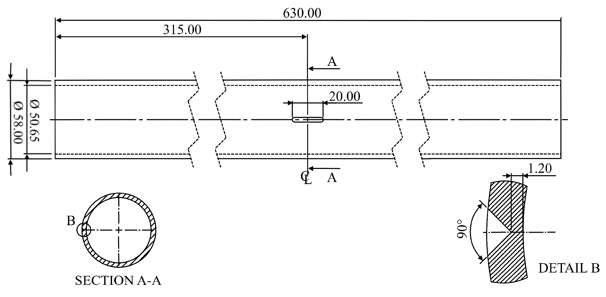
To isolate the effect of fatigue load type, the pipe material and pit geometry were kept constant during all fatigue tests by producing specimens from new BS416-2 pipes [5] and adding artificial pits. Internal water pressure loading causes stress acting in the pipe’s circumferential direction, whereas bending loading primarily causes axial stress. A non-symmetric pit geometry was used to investigate how the corrosion pit shape interacts with the applied stress direction (see Figure 1).

Figure 1.
Fatigue specimen design featuring an axially aligned pit, root radius ~0.2 mm. Not to scale.
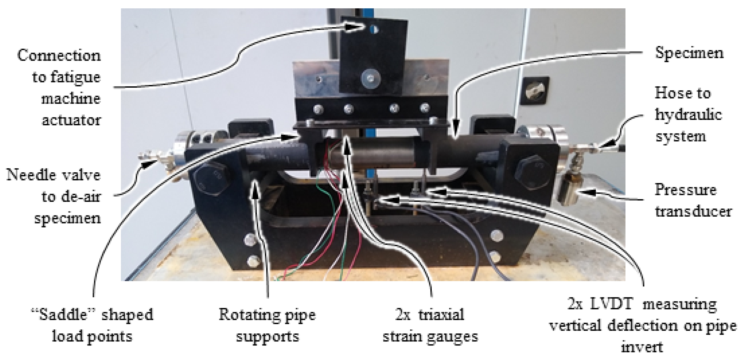
Four-point bending was used to give a region of constant moment away from the influence of the load points. The equipment shown in Figure 2 was used to apply the four-point bending load to specimens, and a walter+bai ag LVF-25-ME servo-hydraulic fatigue testing system provided the vertical fatigue load. To provide a constant amplitude internal pressure load, a bespoke hydraulic testing system was built, capable of applying pressure amplitudes up to 9 MPa at a loading frequency of 2 Hz.

Figure 2.
Labelled photograph showing a pipe specimen loaded into the four-point bending apparatus with instrumentation. This photograph was staged outside the fatigue machine for clarity.
Real-world fatigue loading of GCI water pipes is likely to feature a mean stress, so a load ratio of 0.1 was used (maximum load/minimum load). To capture the fatigue behavior, three tests were run at a single stress level for each configuration. To ensure failures occurred within the high-cycle fatigue regime, tests targeted 5 × 10³ cycles to failure. No specimens tested by John et al. [5] under a load ratio of 0.1 failed between 105 and 2 × 10⁶ cycles, so 105 cycles were used as the runout definition. Failure was defined as the onset of leakage, detected using a Phantom Miro M310 high-speed camera. To observe leakage onset during the bending tests, a low static internal water pressure was applied.
3. Results
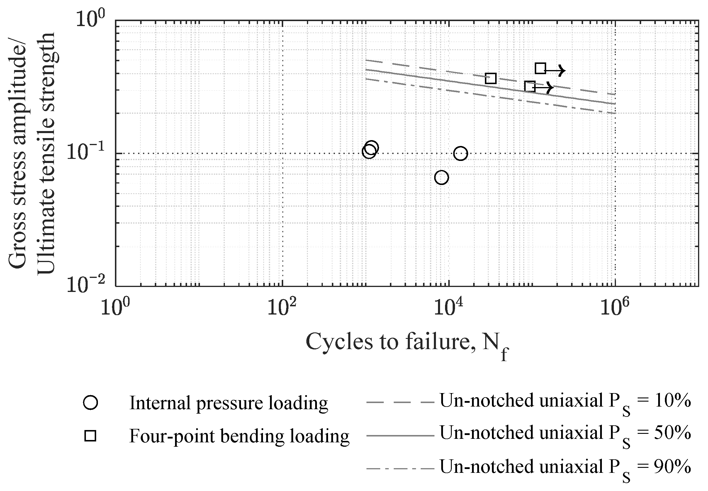
The fatigue results are plotted in Figure 3 with the un-notched uniaxial R = 0.1 fatigue curves from John et al. [5] for comparison. An internal pressure scoping test at a lower stress amplitude is included in Figure 3. Only one of the bending fatigue tests failed before 105 load cycles. A higher stress amplitude was not possible due to equipment limitations.
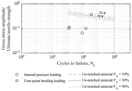
Figure 3.
Plot showing the sharp axial notch specimen fatigue test data. The un-notched uniaxial fatigue curve from John et al. [5] is included for reference.
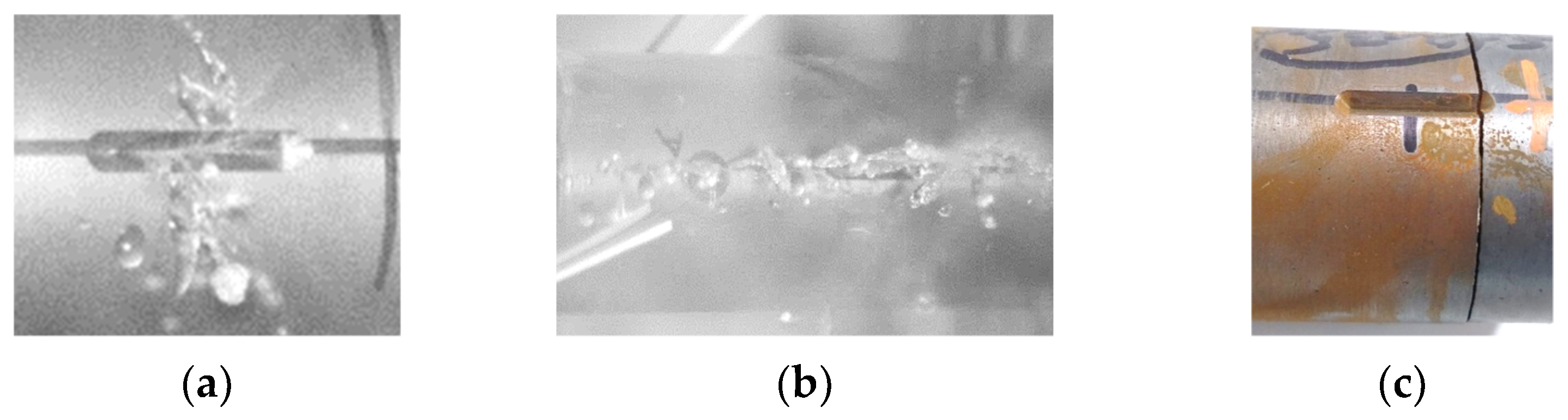
All specimens subject to internal pressure fatigue loading developed an axially aligned crack at the root of the pit that allowed water loss (Figure 4a). For the two specimens that failed after ~103 load cycles, the crack leaked for ~100 load cycles and then grew beyond the notch in a single load cycle, resulting in a leaking crack >100 mm long (Figure 4b). One pipe that failed after ~104 load cycles leaked for ~200 load cycles without the crack growing beyond the pit, while the other leaked for ~2000 load cycles without the crack growing. These two tests were stopped automatically because of pressure load drop.
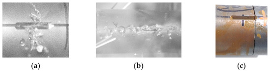
Figure 4.
Images showing specimen failure modes: (a) A leaking axial crack contained within the pit; (b) a leaking axial crack extending beyond the pit; (c) a circumferential crack post-test.
The only four-point bending fatigue specimen that failed developed a circumferential crack during a single load cycle located at one end of the pit (Figure 4c). This failure did not trigger the high-speed camera due to a lighting issue. Gradual pressure drops were detected for the internal pressure loading specimens that coincided with leakage. No pressure drop was detected for the failed four-point bending fatigue specimen, indicating that no leakage occurred before the full-circumferential crack formed.
4. Discussion
The failure observations for the specimens subject to internal pressure fatigue loading show clear evidence for leak-before-burst behavior. This observation is consistent with Rathanayaka et al. [6]. The measured leak-before-break intervals indicate that longer fatigue lives correspond to a longer period of stable leakage. Considering that longer fatigue lives are expected at lower stress amplitudes, WDNs with calmer pressures may provide the conditions for longer leak-before-burst intervals.
Despite having a longer fatigue life than any of the internal pressure loading specimens, the failed four-point bending specimen did not show any signs of leakage before ‘bursting’. This observation suggests that bending fatigue loading does not allow leak-before-burst behavior, although additional test data are required to confirm this. Circumferential failures are reportedly more common for small-diameter GCI water pipes [7], potentially making leak-before-burst behavior less prevalent for these pipes.
Figure 3 shows that, when subject to internal water pressure loading, the presence of the sharp axial notch reduced the fatigue strength of the specimens by 3.4–5.4 times relative to un-notched uniaxial loading. When four-point bending loading was applied to the same specimen design, the fatigue strength was slightly greater than the un-notched uniaxial case. These results show that the direction of the applied fatigue stress relative to an irregular corrosion pit significantly affects the detrimental effect of the corrosion pit, meaning the damage caused by a pit is a function of the pit’s geometry and the loading applied to the pipe. Condition assessments of corroded GCI water pipes must consider both the three-dimensional shape of the corrosion pitting and the loading experienced by the pipe to give a true assessment of the damage caused by a given corrosion pit.
5. Conclusions
This work investigated the effect of fatigue loading type on the remaining life and failure mode of corroded GCI pipes. The following conclusions were drawn:
- Pitted GCI pipes subject to internal water pressure fatigue loading can leak before they burst, and longer leakage periods appear to correlate with longer fatigue lives;
- Condition assessments of corroded GCI water pipes must consider both the three-dimensional shape of the corrosion pitting and the loading experienced by the pipe to give a true assessment of the damage caused by a corrosion pit.
Author Contributions
Conceptualization, J.B., R.C., E.B. and L.S.; methodology, E.J., J.B., R.C., E.B. and L.S.; software, E.J.; validation, E.J.; formal analysis, E.J.; investigation, E.J.; resources, E.J.; data curation, E.J.; writing—original draft preparation, E.J.; writing—review and editing, J.B., R.C., E.B. and L.S.; visualization, E.J.; supervision, J.B., R.C., E.B. and L.S.; project administration, L.S.; funding acquisition, J.B., R.C., E.B. and L.S. All authors have read and agreed to the published version of the manuscript.
Funding
This research was funded by UK Water Industry Research (UKWIR) and the Engineering and Physical Sciences Research Council (EPSRC) through the Water Infrastructure and Resilience (WIRe) Centre for Doctoral Training (EPSRC funding reference: EP/S023666/1).
Institutional Review Board Statement
Not applicable.
Informed Consent Statement
Not applicable.
Data Availability Statement
The original contributions presented in the study are included in the article; further inquiries can be directed to the corresponding author.
Acknowledgments
The authors would like to thank Dennis Dellow of UKWIR and the University of Sheffield technicians Paul Blackbourne, Sam Gibson, Kieren Howarth, Kieran Nash, Martin Taylor, Andrew Fairburn, and Paul Bentley. For the purpose of open access, the author has applied a Creative Commons Attribution (CC BY) license to any author-accepted manuscript versions arising.
Conflicts of Interest
The authors declare no conflicts of interest.
References
- Sanders, J.; Marshallsay, D.; Mountfort, G.; Fox, G.; Butler, M. A Leakage Routemap to 2050; Water UK: London, UK, 2022. [Google Scholar]
- Zhang, C.; Rathnayaka, S.; Shannon, B.; Ji, J.; Kodikara, J. Numerical interpretation of pressurized corroded cast iron pipe tests. Int. J. Mech. Sci. 2017, 128–129, 116–124. [Google Scholar] [CrossRef]
- Brevis, W.; Susmel, L.; Boxall, J. Investigating in-service failures of water pipes from a multiaxial notch fatigue point of view: A conceptual study. Proc. IME C J. Mech. Eng. Sci. 2015, 229, 1240–1259. [Google Scholar] [CrossRef]
- Wang, D. Application and Evaluation of Non-Destructive Testing Methods for Buried Pipes. Master’s Thesis, Queen’s University, Kingston, ON, Canada, 2017. [Google Scholar]
- John, E.; Boxall, J.; Collins, R.; Bowman, E.; Susmel, L. Multiaxial fatigue of water pipe grey cast iron. Int. J. Fatig. 2024, 178, 108002. [Google Scholar] [CrossRef]
- Rathnayaka, S.; Shannon, B.; Jiang, R.; Kodikara, J. New laboratory test facility developed to investigate the leak-before-break window of large-diameter cast iron water pipes. J. Pipeline Syst. Eng. Pract. 2018, 9, 04018010. [Google Scholar] [CrossRef]
- Barton, N.; Farewell, T.; Hallett, S.; Acland, T. Improving pipe failure predictions: Factors effecting pipe failure in drinking water networks. Water Res. 2019, 164, 114926. [Google Scholar] [CrossRef] [PubMed]
Disclaimer/Publisher’s Note: The statements, opinions and data contained in all publications are solely those of the individual author(s) and contributor(s) and not of MDPI and/or the editor(s). MDPI and/or the editor(s) disclaim responsibility for any injury to people or property resulting from any ideas, methods, instructions or products referred to in the content. |
© 2024 by the authors. Licensee MDPI, Basel, Switzerland. This article is an open access article distributed under the terms and conditions of the Creative Commons Attribution (CC BY) license (https://creativecommons.org/licenses/by/4.0/).