Proceeding Paper

Experimental Study of the Pin Loads in a Full Pinion Engagement Planetary Gear Train †

by
Vladislav Ivanov
1,*,
Angel Alexandrov
1,
Dragomir Vrazhilski
1,
Elitsa Tomova-Damyanova
1,
Veselin Tsonev
2,
Nikola Kuzmanov
2 and
Aleksandar Popov
3
1
Faculty of Mechanical Engineering, Technical University of Sofia, 1756 Sofia, Bulgaria
2
Faculty of Transport, Technical University of Sofia, 1756 Sofia, Bulgaria
3
Faculty of German Engineering and Industrial Management, Technical University of Sofia, 1756 Sofia, Bulgaria
*
Author to whom correspondence should be addressed.
Presented at the International Conference on Electronics, Engineering Physics and Earth Science (EEPES’24), Kavala, Greece, 19–21 June 2024.
Eng. Proc. 2024, 70(1), 13; https://doi.org/10.3390/engproc2024070013
Published: 31 July 2024

Abstract

:
Very few experimental studies of full pinion engagement planetary gear trains have been published; therefore, their behavior under load is little known. In this paper, the results from the experimental studies of the above-mentioned gear trains are presented, whereby the bending stresses in the planet pins are displayed both in time and frequency domains by means of fast Fourier transform (FFT). The experiments are conducted on a mechanical closed-loop test rig, which was designed especially for the experiments. The bending stresses in the pins are measured by strain gauges, which are mounted in a double half-bridge configuration, thus showing the stresses in two perpendicular planes. The torque applied is 200 Nm. The radial run-out errors of the planets are measured and their relation to the pin loads are analyzed.

1. Introduction

Planetary gear trains show some distinctive features, which make them a preferred choice for applications where a compact design and significant power density is needed. Such applications include robotics [1], the automotive industry, wind turbines, etc. Their advantage over other types of gear trains is mainly based on the possibility for splitting the torque between several planet branches. On the other hand, though, the torque splitting can be compromised by different manufacturing and assembly errors, which are classified in [2] in three categories, including pinhole position and diameter deviations, planet tooth thickness and bore diameter deviations, and gear eccentricities. Additionally, in [3] the non-equal radial clearances of the planet bearings are considered to have the same negative impact on the load sharing as the pinhole position deviations.
The aforementioned errors concern full pinion engagement planetary gear trains (Figure 1) as well, whereby they not only impair the theoretically highest potential load split but also change the direction of the power flow, as suggested in [4].
To analyze the load sharing behavior of a full pinion engagement planetary gear train, a test rig is built, which is described in greater detail in [5]. The emphasis in this paper is on the influence of the radial run-out errors of the planets on the load of the pins, on which the planets are mounted. To quantify that influence, an FFT analysis is carried out, which is a commonly used analysis tool especially for identifying gear faults such as tooth damage, wear, pitting, scuffing, spalling, backlash, unbalanced inertia masses, run-out, and alignment errors [6,7,8].

2. Description of the Experiment
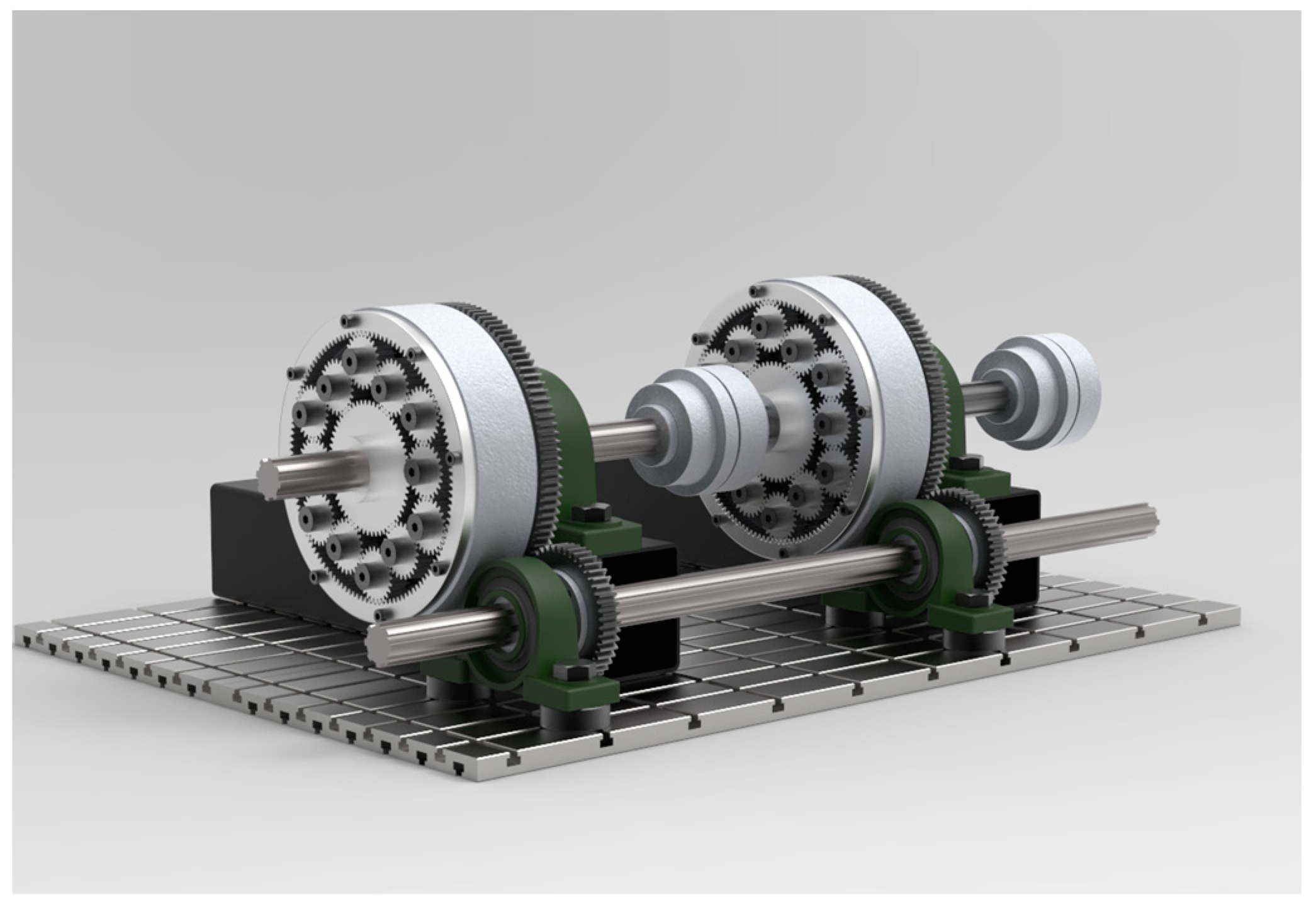
The experiments which are presented in this paper are based on the methodology for measuring planet load sharing proposed by [1], where the loads carried by the planets are measured through strain gauges mounted directly on the planet pins. The methodology requires that the planetary gear train operates in one-degree-of-freedom mode with a fixed carrier. The tests are conducted at one value of the input torque—200 Nm.

2.1. The Test Rig

For conducting the experiments, a mechanical closed-loop test rig was used. The concept of the closed loop, which was used in similar investigations [9,10,11,12], is suitable for testing high-power gear trains, while the energy consumption is kept on a low level since the external motor is used for delivering the rotational motion and for compensating the power losses only.
In our particular case, the test rig consists of two identical full pinion engagement planetary gear trains, whereby the torque is introduced in the system through the input shaft where the sun gears are mounted. A secondary shaft is used for closing the loop through the ring gears (Figure 2). The reaction force in the carrier is used to control the amount of torque, which circulates in the system. Typically, in planetary gear trains, at least one component, usually the sun gear, is allowed to float radially, thus improving the load distribution between the planets. In our case, there are two floating members—the sun and the ring gear. The motivation for choosing this configuration is to allow both inner and outer planets and, respectively, their pins to move and deform.
With a theoretical input speed of 33.3 min−1 of the sun gear the main parameters of the gear set, which are relevant to this study, are shown in Table 1.

2.2. The Measurement System

The stresses in the pins were measured by using HBM 1LY11 3/350 strain gauges, which were mounted in a double half-bridge configuration, allowing for the measurement of the stress in two perpendicular planes—radial and tangential—with respect to the central coordinate system of the gear set (Figure 3).
An HBM Spider 8 strain amplifier was used for the data acquisition. The strain measured during the experiments was recorded with a sampling frequency of 800 samples per second.
The strain, ε, experimentally measured in two perpendicular plains, was converted to bending stress, σ, using Hooke’s law.

3. The Experimental Results

The experimentally acquired data are first displayed in the time domain using the stress vs. time format. The duration of the recording is 10.5 s, which results in a total of 8400 values for the bending stress σ. An FFT analysis is then made to present the results in the frequency domain. For that purpose, the library scipy.fft.rfft is used, whereby the 1-D n-point discrete Fourier transform of a real valued array is computed and an orthographic normalization is made for all the elements. A signal detrend is made to avoid peaks at a frequency of 0 Hz.
The experimental results for three neighboring planets, numbered 1, 2, and 12 in Figure 1, i.e., one external and two internal ones, are shown respectively in Figure 4, Figure 5, and Figure 6. Due to the double half-bridge configuration of the strain gauges, a comparison can be made between the pin’s bending stresses in the radial and tangential directions. The torque applied is 200 Nm.
When analyzing the results, it is noticeable that there are several distinct peaks in the frequency domain, which are given in Table 2. A height threshold of 0.02 is set for the stress magnitude; therefore, only values above 0.02 are shown in the table.
Comparing the results from Table 2 with the rotational frequencies of the main components, given in Table 1, allows the following conclusions to be drawn:
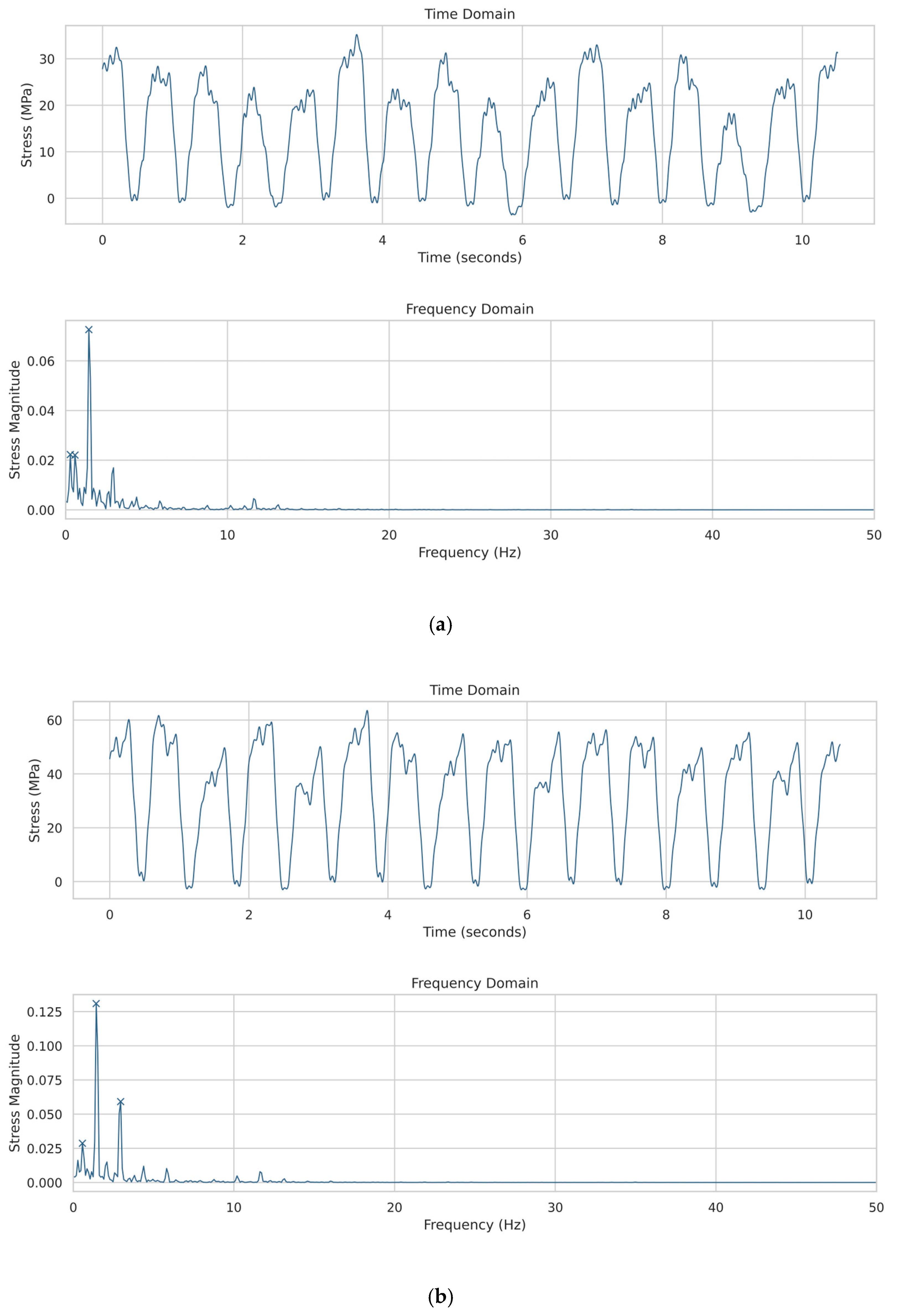
  • The highest stress magnitudes, varying in the range 0.0498 ÷ 0.1309 at frequency 1.4284, correspond to the rotational frequency of the planets;
  • The next highest stress magnitudes in the range 0.022 ÷ 0.0498 at frequency 0.5714 correspond to the sun gear rotational frequency;
  • The lowest values for the stress amplitudes, varying between 0.022 and 0.026, were recorded at frequency 0.2857, which is the ring gear rotational frequency.
  • The frequencies 1.1427 Hz and 2.9520 Hz do not coincide with any of the rotating components’ frequencies. The first of the two, however, is two times higher than the sun gear frequency and four times higher than the ring gear frequency so that it can be considered a sun gear harmonic or a ring gear harmonic. The frequency 2.9520 Hz is 2.06665 higher than the planet frequency, which means that it might be a harmonic, although it differs from the theoretically ideal value, but due to the limited number of experiments which were conducted on that specific test rig, an explanation is still hard to make.
The most obvious reason for the presence of pin bending stress magnitudes at the frequencies of the sun gear, the ring gear, and the planets is the radial run-out errors of the gears themselves. Table 3 presents these errors for the three planets that are the subject of this research.
The design of the test rig allows one to record the variations in the torque, which is applied through the carrier. The results in the time and frequency domains are presented in Figure 7.
Here, some similarities with the results for the pin bending stresses from the previous figures can be observed, viz., there exist three frequencies at which torque magnitude peaks exist. The highest torque magnitude is at 0.2857 Hz, which is the ring gear rotational frequency. The second highest magnitude at 0.6666 Hz corresponds to the rotational frequency of the secondary shaft, which is used to close the loop, and results from the radial run-out of the respected gears (Figure 2). The third significant magnitude appears at the rotational frequency of the planets, i.e., 1.4284 Hz.

4. Conclusions

In conclusion, the following key points of the experimental studies can be indicated:
  • The radial run-out errors significantly influence the load in general and the load distribution in particular between the planets in full pinion engagement planetary gear trains;
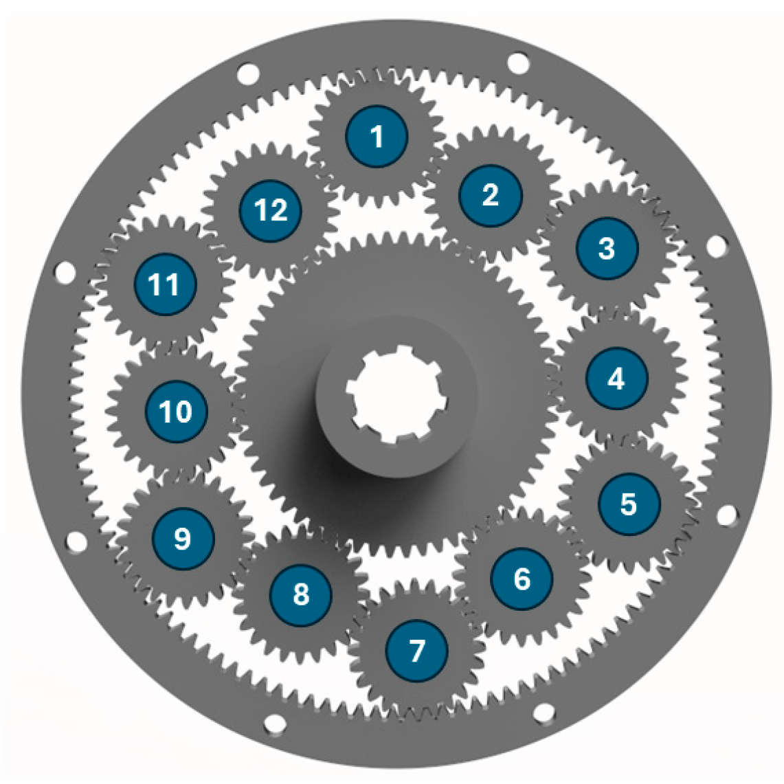
  • Due to the specific arrangement of the gear set components, a direct correlation between the planets’ radial run-out errors and the stress magnitudes of their pins cannot be made. This becomes clear when comparing the results from Table 2 with the values for the run-out errors presented in Table 3, namely, the highest stress magnitudes are observed in tangential direction of planet 12, which shows the lowest eccentricity of all three planets. On the other hand, the stress magnitude in the tangential direction of planet 1, which has the highest run-out of all twelve planets, has its lowest value of 0.0498.
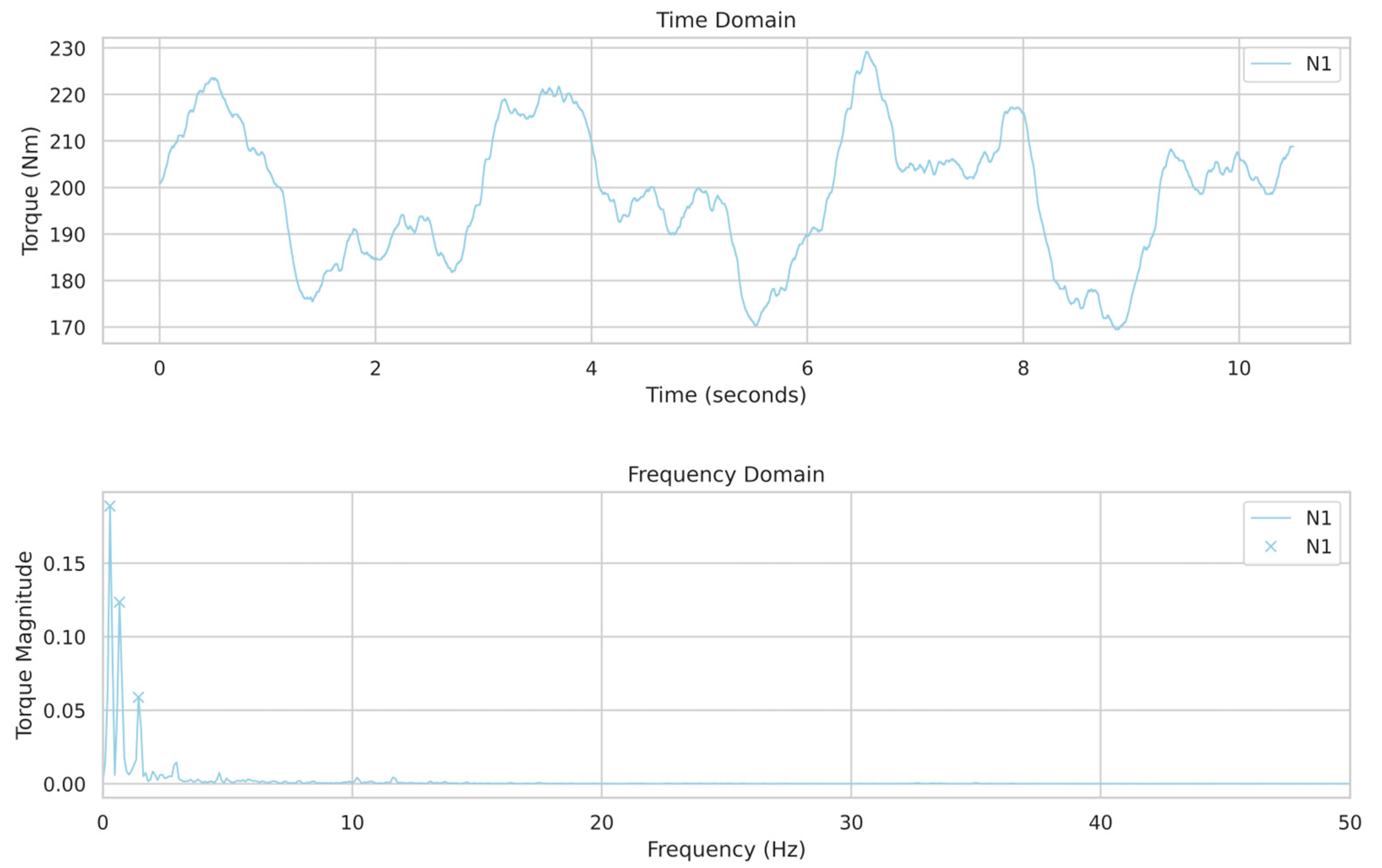
  • The experimental results, which are presented in Figure 7, show that the radial run-out errors of the planets can play a significant role in shaping the torque curve. The same applies to the sun gear and the ring gear. Another important issue, which can be observed in the above-mentioned figure, is the influence of the test equipment on the experimental results. In this respect, the FFT analysis helps isolate that influence and put an emphasis on the impact of the parameters under study.

Author Contributions

Conceptualization, V.I. and V.T.; methodology, V.I. and D.V.; investigation, V.I., A.A., A.P., and N.K.; resources, V.I. and A.A.; writing—original draft preparation, V.I.; writing—review and editing, E.T.-D.; visualization, A.A. and E.T.-D.; funding acquisition, V.I. All authors have read and agreed to the published version of the manuscript.

Funding

This research was funded by the Research and Development Sector at the Technical University of Sofia, grant number 231ИП0019-06.

Institutional Review Board Statement

Not applicable.

Informed Consent Statement

Not applicable.

Data Availability Statement

The data presented in this study are available on request from the corresponding author. The data are not publicly available due to privacy restrictions.

Acknowledgments

The authors would like to thank the Research and Development Sector at the Technical University of Sofia.

Conflicts of Interest

The authors declare no conflicts of interest.

References

  1. Chavushyan, V.; Nikolov, S.; Georgieva, V. Study of problems in application and design of SCARA robots in the semiconductor industry. AIP Conf. Proc. 2024, 3063, 060011. [Google Scholar]
  2. Boguski, B.; Kahraman, A.; Nishino, T. A new method to measure planet load sharing and sun gear radial orbit of planetary gear sets. In Proceeding of the ASME 2011 International Design Engineering Technical Conferences & Computers and Information in Engineering Conference IDETC/CIE 2011, Washington, DC, USA, 28–31 August 2011. [Google Scholar]
  3. Arnaudov, K.; Karaivanov, D. Planetary Gear Trains; Taylor & Francis Group, LLC.: Abingdon, UK, 2019. [Google Scholar]
  4. Ivanov, V. Load sharing analysis of a full pinion engagement planetary gear train. AIP Conf. Proc. 2024, 3063, 060004. [Google Scholar]
  5. Ivanov, V.; Aleksandrov, A.; Tsonev, V.; Kuzmanov, N.; Troha, S.; Dimitrov, L. The effect of external forces on the load sharing of a full planet engagement planetary gear train. In Proceedings of the International Conference on Communications, Information, Electronic and Energy Systems (CIEES 2022), Veliko Tarnovo, Bulgaria, 24–26 November 2022. [Google Scholar]
  6. Shivputra, A.; Shrigandhi, G. Gear Fault Identification by using Vibration Analysis. Int. J. Curr. Eng. Technol. 2016, 247–253. Available online: https://inpressco.com/category/ijcet (accessed on 25 May 2024).
  7. Aherwar, A. An investigation on gearbox fault detection using vibration analysis techniques: A review. Aust. J. Mech. Eng. 2012, 10, 169–183. [Google Scholar] [CrossRef]
  8. Vernekar, K.; Kumar, H.; Gangadharan, K.V. Gear fault detection using vibration analysis and continuous wavelet transform. Procedia Mater. Sci. 2014, 5, 1846–1852. [Google Scholar] [CrossRef]
  9. Dimitrov, L.; Michalopoulos, D.; Apostolopoulos, C.A.; Neshkov, T. Investigation of Contact Fatigue of High Strength Steel Gears Subjected to Surface Treatment. J. Mater. Eng. Perform. 2008, 18, 939–946. [Google Scholar] [CrossRef]
  10. Mozafari, S.; Rezazadeh Mohamadi, M.; Dolatkhah Takloo, S.; Mardani, M. Design of a mechanically closed-loop test rig for testing aviation industry’s gearboxes. Aviation 2017, 21, 132–142. [Google Scholar] [CrossRef]
  11. Lee, G.-H.; Park, Y.-J.; Nam, J.-S.; Oh, J.-Y.; Kim, J.-G. Design of a Mechanical Power Circulation Test Rig for a Wind Turbine Gearbox. Appl. Sci. 2020, 10, 3240. [Google Scholar] [CrossRef]
  12. Mihailidis, A.; Athanassios, I. A new system for testing gears under variable torque and speed. Recent Pat. Mech. Eng. 2009, 2, 179–192. [Google Scholar] [CrossRef]
Figure 1. Full pinion engagement planetary gear train with 12 planets.
Engproc 70 00013 g001
Figure 2. Mechanical closed-loop test rig.
Engproc 70 00013 g002
Figure 3. Strain gauges mounted in a double half-bridge configuration.
Engproc 70 00013 g003
Figure 4. Experimental results in time and frequency domain for planet 1: (a) in radial direction; (b) in tangential direction.
Engproc 70 00013 g004
Figure 5. Experimental results in time and frequency domain for planet 2: (a) in radial direction; (b) in tangential direction.
Engproc 70 00013 g005
Figure 6. Experimental results in time and frequency domain for planet 12: (a) in radial direction; (b) in tangential direction.
Engproc 70 00013 g006
Figure 7. Torque applied to the test rig.
Engproc 70 00013 g007
Table 1. Main components’ parameters.
GearNumber of TeethRotational Frequency [Hz]
Module m = 2 mm
Sun gear600.56
Ring gear1200.28
Inner planet241.4
Outer planet241.4
Table 2. Experimental results in the frequency domain.
Planet NumberFrequency [Hz]Stress Magnitude
1—radial direction0.57140.0298
1.42840.0921
2.95200.0330
1—tangential direction0.57140.0498
1.14270.0202
1.42840.0498
2—radial direction0.28570.0267
0.57140.0271
1.42840.1257
2.95200.0209
2—tangential direction0.57140.0315
1.14270.0234
1.42840.0848
12—radial direction0.28570.022
0.57140.022
1.42840.0726
12—tangential direction0.57140.0286
1.42840.1309
2.95200.0592
Table 3. Radial run-out errors of the planetary gears.
Planet NumberRadial Run-Out [mm]
10.25
20.19
120.09
Disclaimer/Publisher’s Note: The statements, opinions and data contained in all publications are solely those of the individual author(s) and contributor(s) and not of MDPI and/or the editor(s). MDPI and/or the editor(s) disclaim responsibility for any injury to people or property resulting from any ideas, methods, instructions or products referred to in the content.

