Abstract
In this article, the development of a software system—a simulator for testing software systems using a binary protocol—is proposed. The purpose of the development is to achieve full testing of a wide class of software systems. They are directly related to the management of hardware systems, with which communication is based on a binary protocol. The developed simulator allows different types of messages to be simulated during real communication. In this way, it is possible to check how a given program system would react to correct and incorrect messages in the communication stage. This article presents a GUI system developed in the standard C++ programming language and the Qt platform, which makes it platform-independent. The system provides the ability to select preset commands via an external file or enter/correct commands in real-time. The commands may be different depending on the integration scope of the binary protocol. The connection between the developed simulator and the tested system is through RS 232 interface. Configuring settings and testing binary protocols through the developed application becomes fast and intuitive.
1. Introduction
This paper [1] proposes an approach to represent a binary protocol in a state machine, which enables automatic generation of state patterns for binary protocol by listening to the network. A methodology for field alignment in the binary protocol, their extraction, and construction of the protocol model are implemented. The experimental results of ARP and TCP show that the approach is effective.
Binary protocols do not have session flow characteristics. To achieve binary protocol data identification, an unsupervised clustering algorithm based on enhanced principal component analysis (PCA) and density peak clustering (DPC) is proposed. The authors of [2] propose to improve PCA by determining the dimensionality of PCA based on information acquisition. Enhanced PCA can remove redundant information and preserve the features of the original data.
The authors of [3] propose a Biprominer tool that can automatically extract binary message protocol formats of an application from its real-world network trace. The main feature of Biprominer is that it does not need to have any prior knowledge of protocol formats, as Biprominer is based on the statistical nature of the protocol format.
The authors of [4] propose a Veritas system that automatically infers the protocol state machine from real-world network traces. The main feature of Veritas is that no prior knowledge of the protocol specifications is required, and the work is based on the statistical analysis of the protocol formats. The authors define a new model—a probabilistic protocol state machine (P-PSM).
The authors of [5] introduce the RecordFlux toolkit and language. The RecordFlux Domain Specific Language (DSL) is used to specify the protocol version and verify the correctness of the generated code using the SPARK toolkit.
The authors of [6] introduce a method based on the symbolic execution of multiple packets, which can bring the software to deep states to test the entire binary software stack of the network protocol. This paper also presents a prototype system, S2EProtocol-multi [7,8], on the Selective Symbolic Execution (S2E) platform.
In [9], an approach for detecting anomalies and vulnerabilities based on a dynamic binary analysis technique and a semantic-based active testing technique is proposed. The proposed implementation works on the binaries of tested protocol implementations and can detect deviations.
In [10], an automated field semantics inference method for a binary protocol (FSIBP) is proposed. FSIBP aims to automatically learn semantic inference knowledge from known protocols and use it to infer the semantics of each field of an unknown binary protocol. To achieve this goal, a method for extracting the characteristics of the field itself is designed.
A multiple data sequence alignment algorithm [10] based on approximate matching (MSAAM) is implemented to process the data with random error bits. After sequence alignment, a noise-resilient system for extracting protocol formats from binary data is created, combining statistical analysis and a feature library.
2. Purpose of the Development
The program systems using a binary protocol represent systems operating in real time. They send and receive messages mostly via the RS232 interface. Each system sends and receives messages with different content, depending on the application. For development testing, two approaches are used:
- Availability of the physical system to be serviced. It sends and receives real data to the programming system),
- Development of a simulator (software or hardware) that simulates the physical system. It receives and sends real or test data with which operability is verified. The data can be correct or incorrect according to the communication protocol used to fully test the functionality of the application program.
The first approach has the disadvantage that the physical system is not available every time in advance or cannot be used in the application program development process. There are also cases where the two systems are in parallel development and cannot be used together until they are fully completed.
The second approach requires developing a system that can only be used to test one or a few such developments, but not a broad class of applications. This leads to increased costs of time and resources. Moreover, such systems will not be implemented and operated because are intended only for hardware system simulation.
In this article, it is proposed to develop a program simulator that implements a binary protocol and can receive/send messages by connecting via an RS232 interface to the corresponding program system. This simulator is a universal programming system, in terms of messages, because they are performed depending on the respective tested software system and its application.
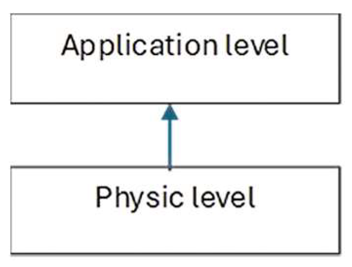
The software systems check messages for correctness at two levels (Figure 1).
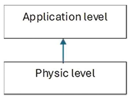
Figure 1.
Message-checking levels.
At the physical level, a message is received as a sequence of bytes. It then checks that a correct message has been received (the correct number of bytes and CRC code, which is calculated when the message is received and compared to the one that was sent).
At the application level, it is checked whether the message corresponds to the expected data to be received (for example, a message should be received from receiver 02 and a message is received from receiver 04, or a status message was sent and another message was received, etc.).
After passing the double-check, the corresponding program system proceeds to the subsequent processing of the received data.
During the actual operation, it is possible that unforeseen situations occur and messages are not sent correctly between the physical and the software system (for example, due to cable interference, unplugged cable, incorrect message formation, etc.).
The developed simulator and the tested software systems are based on a binary communication protocol (Table 1).

Table 1.
Message protocol.
The message contains the following fields:
- Segment Receiver (byte 0)—segment of the recipient—a one-byte field that contains the segment of the device that will receive the data.
- Address Receiver (byte 1)—address of the recipient—a one-byte field that contains the address of the device that will receive the data.
- Segment Sender (byte 2)—address of the sender—a one-byte field that contains the segment of the device that will send the data.
- Address Sender (byte 3)—address of the sender—a one-byte field that contains the address of the device that will send the data.
- Length (byte 4)—length—the length from the next byte to the end of the message is set.
- Command (byte 5)—command—a one-byte field in which a command number is set-
- Parameters—command parameters. These can be from 0 to 249 bytes, which means it can have no parameters, only one parameter, or multiple parameters, with a maximum of 249, since the maximum message length is 256 bytes.
- Checksum—this field is calculated by the sender and the receiver. The calculation is as follows:
- ○
- On the sender’s side—the sum of all bytes from 0 to n−1 bytes is found, and then this difference is subtracted from 255 and the result is recorded in the CRC field.
- ○
- On the recipient’s side—the sum of all bytes from 0 to the n−1st byte is found. The checksum is then added, and if the result is 255, the message is accepted as true.
The maximum length of the message is 256 bytes, and the minimum is 7 bytes.
According to the developed binary protocol (Figure 2), messages are divided into several types:
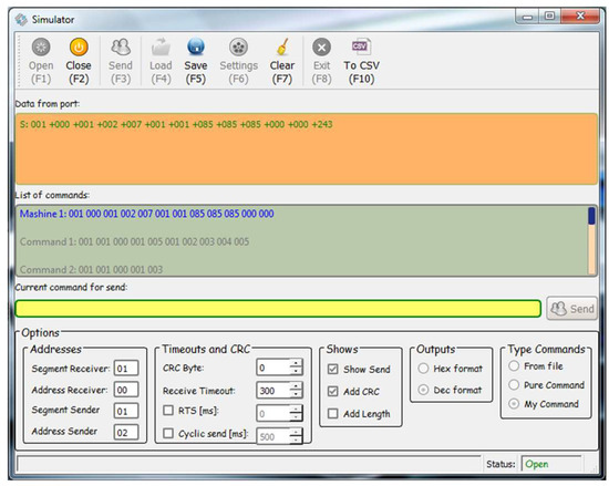
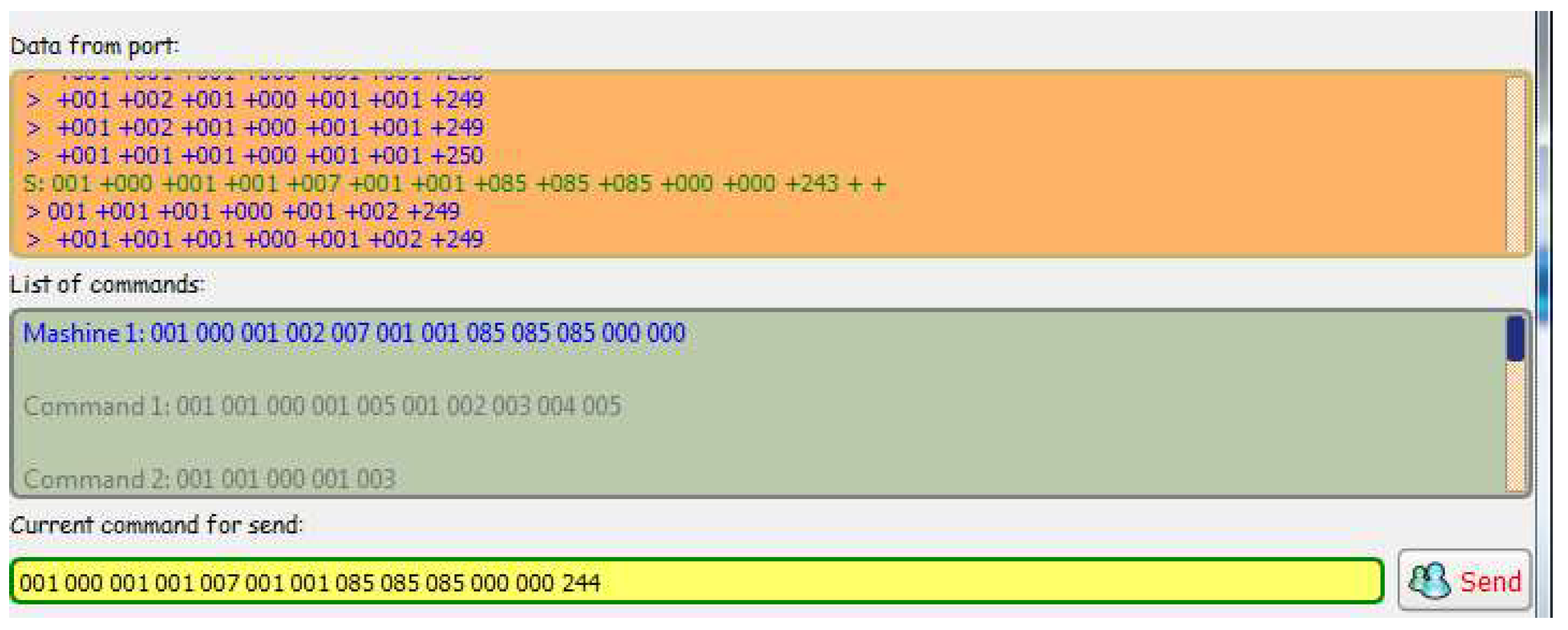
Figure 2.
Simulator home screen.
- A correct message that has all fields and a valid CRC code.
- A bad message that has all fields and the wrong CRC code.
- Short message with missing fields.
- Long message—a message that consists of more fields. In this case, the simulator finds one full message (correct or incorrect) and one more short message:
- ○
- If the extra fields are after the CRC and it is correct, the message is correct; if it is wrong, it is incorrect.
- ○
- If the extra fields are before the CRC, then there is a correct message with the wrong CRC code.
A developed software system must intercept both correct messages and messages that do not correspond to the correct ones according to the communication protocol. As a result of incorrect messages, they should not be processed at the application level because these will contain incorrect and/or partial data. This can lead to unforeseen situations.
The purpose of the simulator is to send different types of test messages to simulate different problem situations and the correct operation of the software system under development. In this way, the behavior of a system can be studied in the presence of correct and incorrect messages on the communication channel.
3. Program Simulator
3.1. Overview
In Figure 2, the simulator home screen is shown.
It consists of:
- Fields for visualizing received and sent messages.
- A field for manual input/correction of messages.
- An ability to load commands from an external file.
- An ability to automatically format a message, when entering only the fields with the data (this allows for the formation of large messages and automatic calculation of the data length and CRC code).
- Options to configure the COM port according to the requirements of the specific application.
3.2. State Machine of Simulator
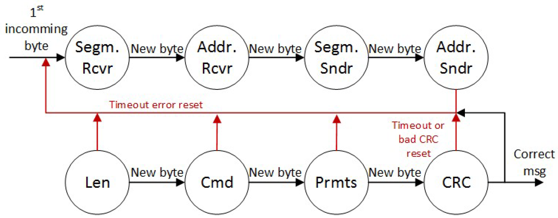
Figure 3 shows the state machine that receives the messages at the physical level. It aims to accept the message from the sender and check it for correctness against the byte-level protocol. Each field of the binary protocol is a state of the machine. When a message is received, there is a set time for which; if the rest of the message is not received, a timeout is generated with an error stating that there is a short message.
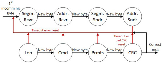
Figure 3.
State machine.
This causes the state machine to restart and protects it from hanging in any of the states. If the state machine goes through all the states and finds that the CRC code is correct, it passes the message on to the application layer for further processing.
4. Experimental Setup
The experimental setup consists of the following components.
- The developed simulator (Figure 2). The simulator is developed in the Qt programming system using C++ program language. Thus, it can be compiled for different operating systems.
- Developed software process control system (the developed server application for machine liquid dosing system is used for testing). This application sends and receives messages to/from liquid dispensing machines, processes the received messages at the physical and application level, and records the data in a database. From this database, another application designed for end users shows the status of the machines, allows for the operation of the machines, etc.
- A computer on which both applications are installed to perform the test experiments.
- Two USB–RS232 converters, with which COM ports are simulated for RS-232 interface connection. Each of the applications works with a unique COM port because it resides on one physical machine.
- Cable for two-way communication, with DB9 connectors. To perform the tests, it is sufficient to connect only the Tx and Rx signals of the two couplers for two-way communication. When performing the tests, the settings of the COM ports must be the same.
5. Experimental Results
To run the tests, one of the liquid dosing server application command sets shown in Table 2 is used. That command is a command for machine status.
Table 2.
Status command.
5.1. Sending the Correct Message Machine of the Simulator
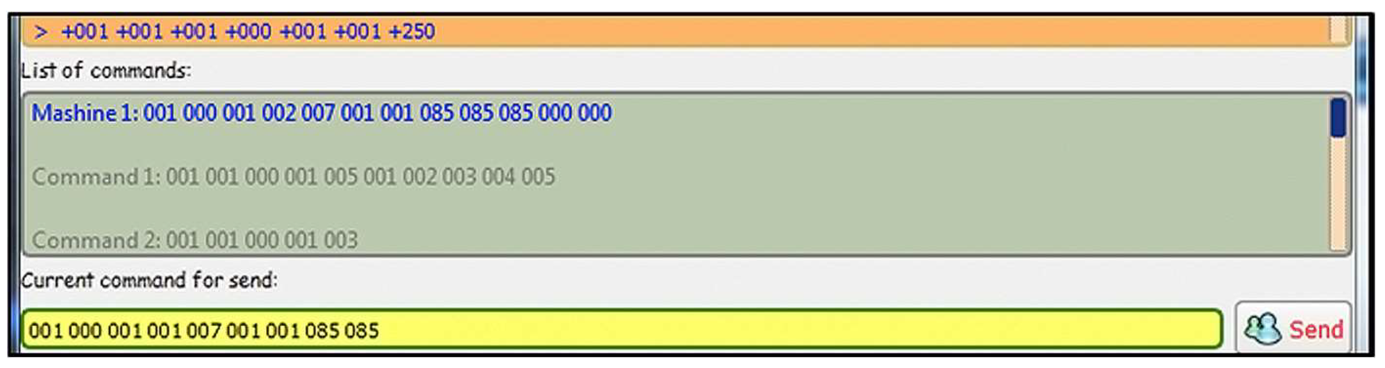
In this test, a correct machine status message is sent from the simulator to the server application (Figure 4).

Figure 4.
The simulator command format for a correct message.
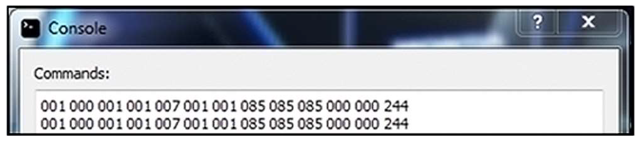
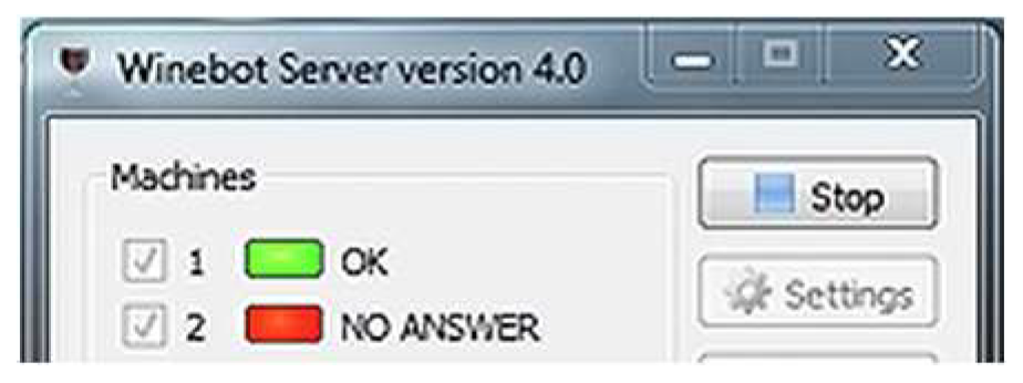
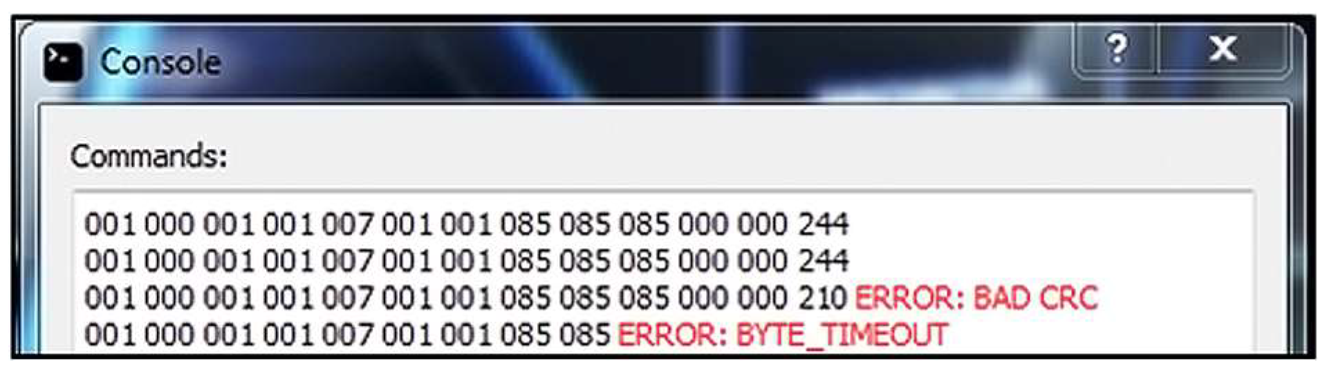
Result: The server application receives the message correctly (Figure 5 and updates the status of the current machine to active (Figure 6). When sending a status message, the server application only checks that the message was sent correctly. In this case, sending a status message to Machine 1 is simulated. Upon receiving a correct message, Machine 1 is marked as active, i.e., it works and can receive and send messages over the communication network.
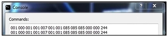
Figure 5.
Sever console application response.

Figure 6.
Server application status for one machine.
5.2. Sending the Message with a Bad CRC Code
In this test, a message with a bad CRC code is sent from the simulator to the server application (Figure 7).
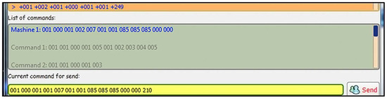
Figure 7.
Simulator command format with a bad CRC.
Result: The server application receives the message correctly, calculates the correct CRC code, and prints an error message for the bad CRC code in the corresponding message field (Figure 8).
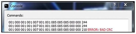
Figure 8.
Server console application response.
5.3. Sending the Short Message
In this test, a short machine status message is sent from the simulator to the server application (Figure 9).
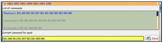
Figure 9.
Simulator command format for a short message.
Result: The server application receives the message, but the state machine generates the timeout error and prints an error message for byte timeout (Figure 10). When receiving a new byte that is part of the message, a timer is started to wait for the next new byte. If the timeout expires, a short message is considered received and a timeout error is generated.
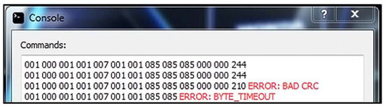
Figure 10.
Server console application response.
6. Conclusions
The test experiments conducted and the obtained results (part of which are shown in this article) show the correctness of the reception of the messages on the communication channel. The simulator developed offers quick and easy configuration of test messages to simulate different communication scenarios in a real environment.
For future work, the system can be expanded with the following functionalities: adding different communication protocols, communication through different protocols (for example, via Ethernet), automatic generation of reports with diagnosed errors, and automatic generation of possible messages for a given system.
Author Contributions
Conceptualization, G.S. and I.B.; methodology, G.S. and I.B.; software, I.B.; validation, G.S. and I.B.; formal analysis, G.S.; investigation, I.B.; resources, I.B.; data curation, G.S.; writing—original draft preparation, G.S. and I.B; writing—review and editing, G.S. and I.B.; visualization, I.B.; supervision, I.B.; project administration, I.B.; funding acquisition, G.S. All authors have read and agreed to the published version of the manuscript.
Funding
This research received no external funding.
Institutional Review Board Statement
Not applicable.
Informed Consent Statement
Not applicable.
Data Availability Statement
Data sharing is not applicable due to privacy.
Conflicts of Interest
The authors declare no conflict of interest.
References
- Meng, F.; Liu, Y.; Zhang, C.; Li, T.; Yue, Y. Inferring protocol state machine for binary communication protocol. In Proceedings of the 2014 IEEE Workshop on Advanced Research and Technology in Industry Applications (WARTIA), Ottawa, ON, Canada, 29–30 September 2014; pp. 870–874. [Google Scholar] [CrossRef]
- Yan, X.; Li, Q.; Tao, S. A clustering algorithm for binary protocol data frames based on principal component analysis and density peaks clustering. In Proceedings of the 2017 IEEE 17th International Conference on Communication Technology (ICCT), Chengdu, China, 27–30 October 2017; pp. 1260–1266. [Google Scholar] [CrossRef]
- Wang, Y.; Li, X.; Meng, J.; Zhao, Y.; Zhang, Z.; Guo, L. Biprominer: Automatic Mining of Binary Protocol Features. In Proceedings of the 2011 12th International Conference on Parallel and Distributed Computing, Applications and Technologies, Gwangju, Republic of Korea, 20–22 October 2011; pp. 179–184. [Google Scholar] [CrossRef]
- Wang, Y.P.; Zhang, Z.B.; Yao, D.F. Inferring Protocol State Machine from Network Traces: A Probabilistic Approach. In Applied Cryptography and Network Security; Lopez, J., Tsudik, G., Eds.; Lecture Notes in Computer Science; Springer: Berlin/Heidelberg, Germany, 2011; Volume 6715. [Google Scholar] [CrossRef]
- Senier, A. Tutorial: The End of Binary Protocol Parser Vulnerabilities: Using RecordFlux and SPARK to implement formally-verified binary formats and communication protocols. In Proceedings of the 2023 IEEE Secure Development Conference (SecDev), Atlanta, GA, USA, 18–20 October 2023; pp. 5–6. [Google Scholar] [CrossRef]
- Wen, S.; Feng, C.; Meng, Q.; Zhang, B.; Wu, L.; Tang, C. Multi-packet symbolic execution testing for network protocol binary software. In Proceedings of the 2016 5th International Conference on Computer Science and Network Technology (ICCSNT), Changchun, China, 10–11 December 2016; pp. 624–627. [Google Scholar] [CrossRef]
- Wen, S.; Feng, C.; Meng, Q.; Zhang, B.; Wu, L.; Tang, C. Model-guided symbolic execution testing for network protocol binary software. In Proceeding of the 2016 International Conference on Progress in Informatics and Computing (PIC), Shanghai, China, 23–25 December 2016; pp. 561–565. [Google Scholar] [CrossRef]
- Wen, S.; Feng, C.; Meng, Q.; Zhang, B.; Wu, L.; Tang, C. Analyzing network protocol binary software with joint symbolic execution. In Proceedings of the 2016 3rd International Conference on Systems and Informatics (ICSAI), Shanghai, China, 19–21 November 2016; pp. 738–742. [Google Scholar] [CrossRef]
- Li, M.; Wang, Y.; Xie, P. A binary analysis method for protocol deviation discovery from implementations. In Proceedings of the International Conference on Information Networking 2013 (ICOIN), Bangkok, Thailand, 28–30 January 2013; pp. 670–675. [Google Scholar] [CrossRef]
- Zhan, M.; Li, Y.; Li, B.; Zhang, J.; Li, C.; Wang, W. Toward Automated Field Semantics Inference for Binary Protocol Reverse Engineering. IEEE Trans. Inf. Forensics Secur. 2024, 19, 764–776. [Google Scholar] [CrossRef]


Disclaimer/Publisher’s Note: The statements, opinions and data contained in all publications are solely those of the individual author(s) and contributor(s) and not of MDPI and/or the editor(s). MDPI and/or the editor(s) disclaim responsibility for any injury to people or property resulting from any ideas, methods, instructions or products referred to in the content. |
© 2024 by the authors. Licensee MDPI, Basel, Switzerland. This article is an open access article distributed under the terms and conditions of the Creative Commons Attribution (CC BY) license (https://creativecommons.org/licenses/by/4.0/).