Advancements in PMSM-Based Commercial Fan Control: Hardware, FOC Implementation, and Performance Evaluation †
Abstract
1. Introduction
- Utilize Hall sensors for precise speed and position control in controlling techniques;
- Develop hardware circuitry and implement field-oriented control (FOC) with space vector modulation in MATLAB simulation;
- Analyze VFD drive tuning and evaluate performance on a PMSM motor.
2. Methodology
2.1. Design and Simulation of Control Algorithm
Proposed Simulink Model
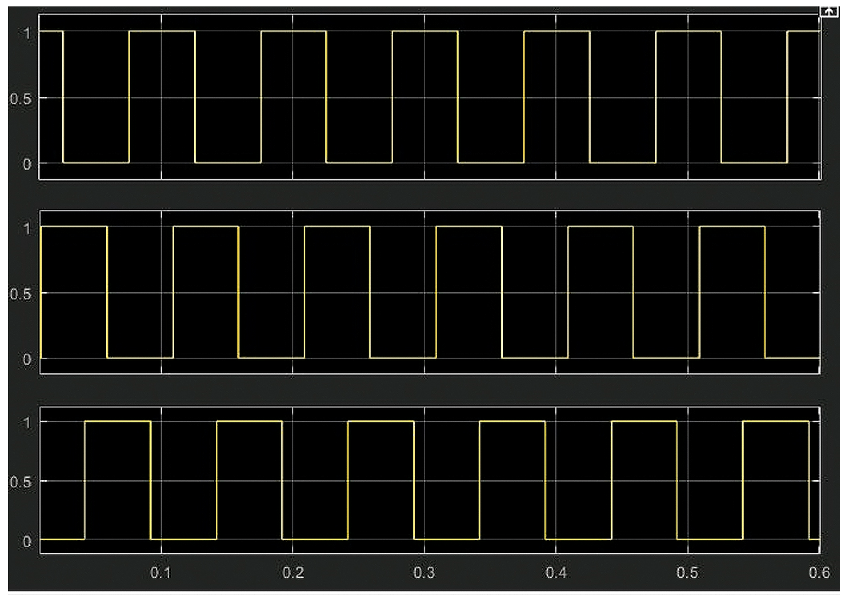
- Hall signal generation: Three Hall signals from a pulse generator are produced with a phase shift of 120°, and at every 60° at least one Hall signal changes its state. The Hall signal MATLAB model is shown in Figure 1.Figure 1. Hall signal MATLAB model.
- Inverter: A DC bus of 36 volts is connected to three half-bridge inverters, which includes MOSFETs as switching devices. Three leg shunt resistors have to sense phase currents, as shown in Figure 2. The mathematically modeled PMSM is used as the load.Figure 2. Inverter with PMSM.
- Motor phase current into DQ frame: Motor phase currents are sensed with three leg shunt resistors. These three phase currents i.e., Ia, Ib, and Ic are modified to direct (Id) and quadrature (Iq) currents using Clarke and Park transformations, as shown in Figure 3.Figure 3. Phase currents into Id and Iq.
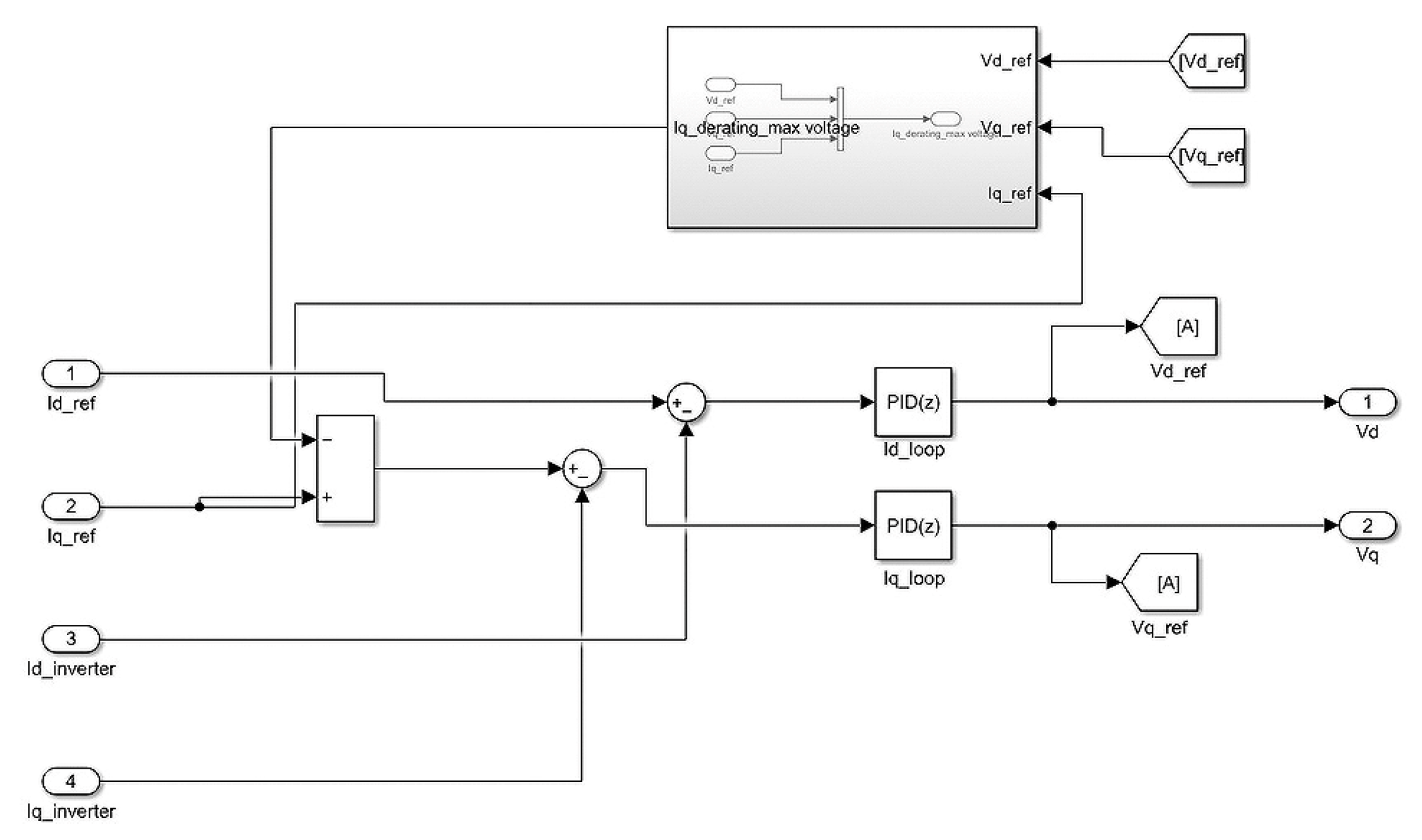
- Current loop: The current loop contains two loops i.e., Id and Iq loops, as shown in Figure 4. Here, the command for Id is set to zero in order to obtain the highest torque i.e., by sustaining 90° between the stator and rotor flux. Kp and Ki of the current loop hold on the bandwidth and electrical time constant ().
- Speed loop: A single PI block is used in the speed loop, where the outcome is the iq command for the current loop, as shown in Figure 5. The Kp and Ki values for the speed loop hold on the bandwidth and mechanical time constant ().

- PWM generation: Three phase quantities using the inverse Park transformations are acquired from the Vd and Vq reference of the current loop and given to the space vector block to produce the 3rd harmonic sinusoidal wave, as shown in Figure 6.Figure 6. PWM generation.
- SVPWM: The generation of three phase voltages from the transformation block is fed into the SVPWM block, to obtain three space vector modification voltages, as shown in Figure 7.Figure 7. Open loop block diagram.
2.2. Tuning of Motors
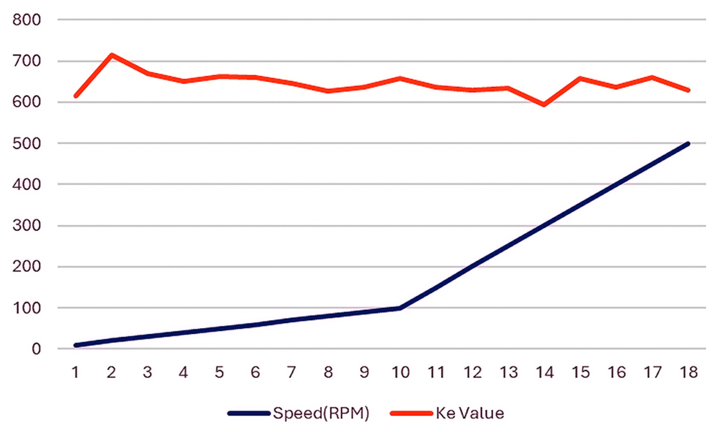
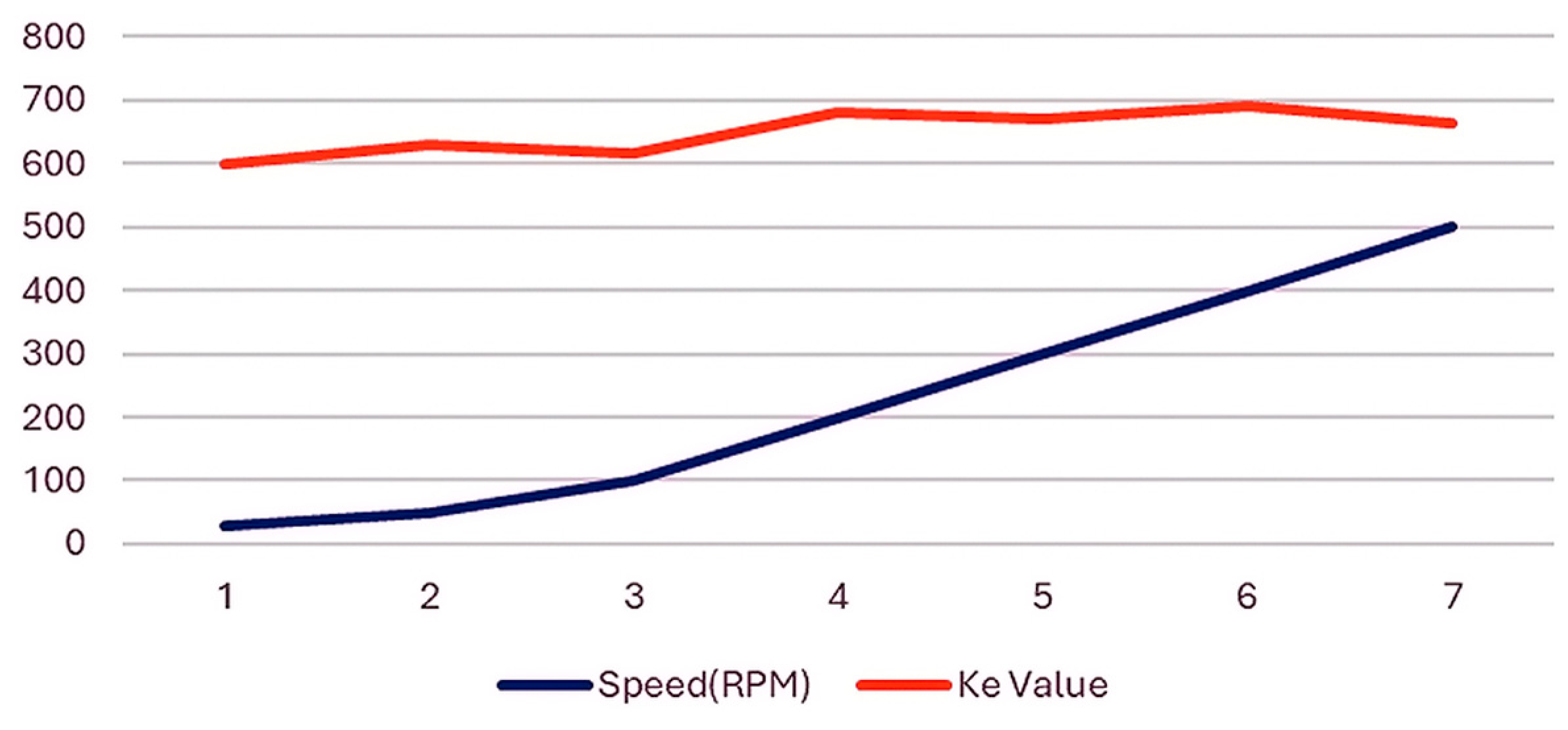
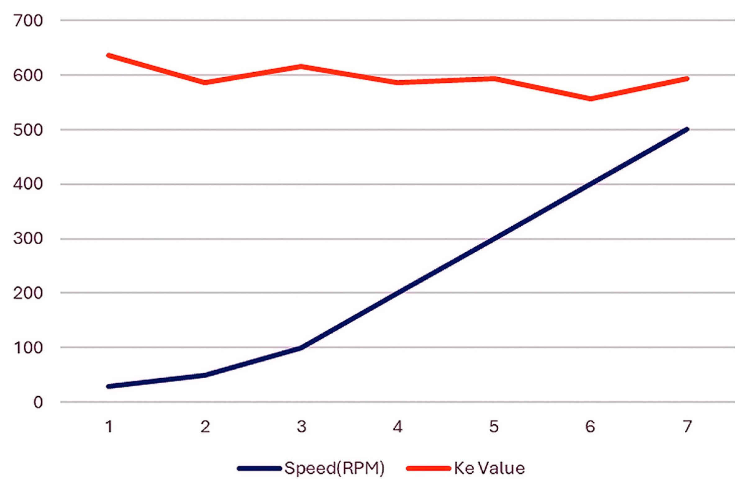
- Motor Back-EMF constant (Ke): If given a motor whose Ke value is not known, or if the value given in the datasheet is not operating, then this can be obtained using the Back-EMF Test. Once the readings are obtained, further work is required. According to the test, we obtain numerous readings of the Back-EMF voltage and speed (at which the voltage is measured). In MCE Designer, the Back-EMF constant is described as V(ln-rms)/ krpm. The measured EMF will be between lines (RMS), but in MCE Designer it is described as line-neutral (RMS). Hence, using this equation would transform the measured value in MCE Designer into a suitable value. Units are in V(ln-rms)/krpm.
- Motor torque constant, Kt can be approximated from the Ke (BEMF constant).
- Rph (phase resistance/motor resistance)
- Lph (phase inductance/motor Ld and Lq inductance)
- Poles
- Rated current/allowed current
- Inertia of the load/motor
- Hardware Development
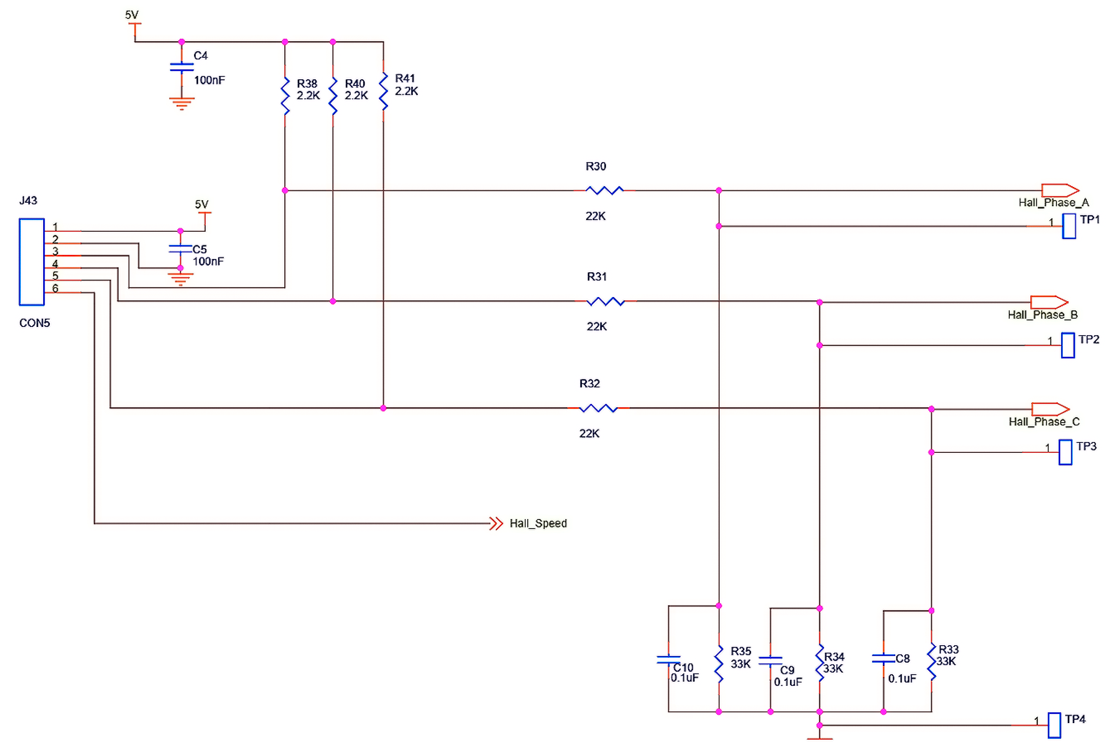
- Hall Sensor Schematics
- Battery Voltage Monitoring
- Decoupling Capacitors
- MOSFET Selected
- Microcontroller selection
3. Results and Discussion
3.1. Simulation Hall Sensor Waveform
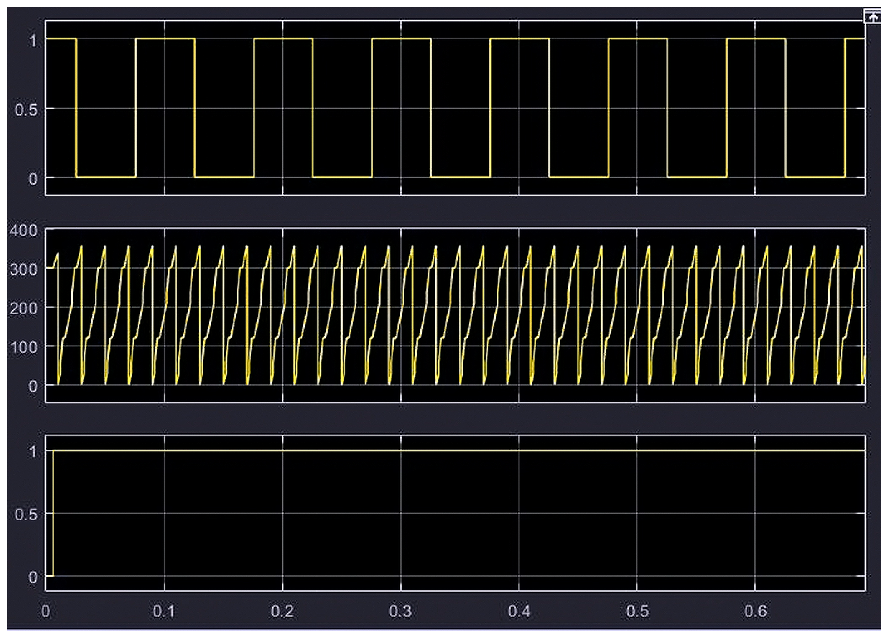
3.2. Ramp Generation from 0° to 360° and Direction of the Motor
3.3. Outcomes Taken from the Motor Control Algorithm
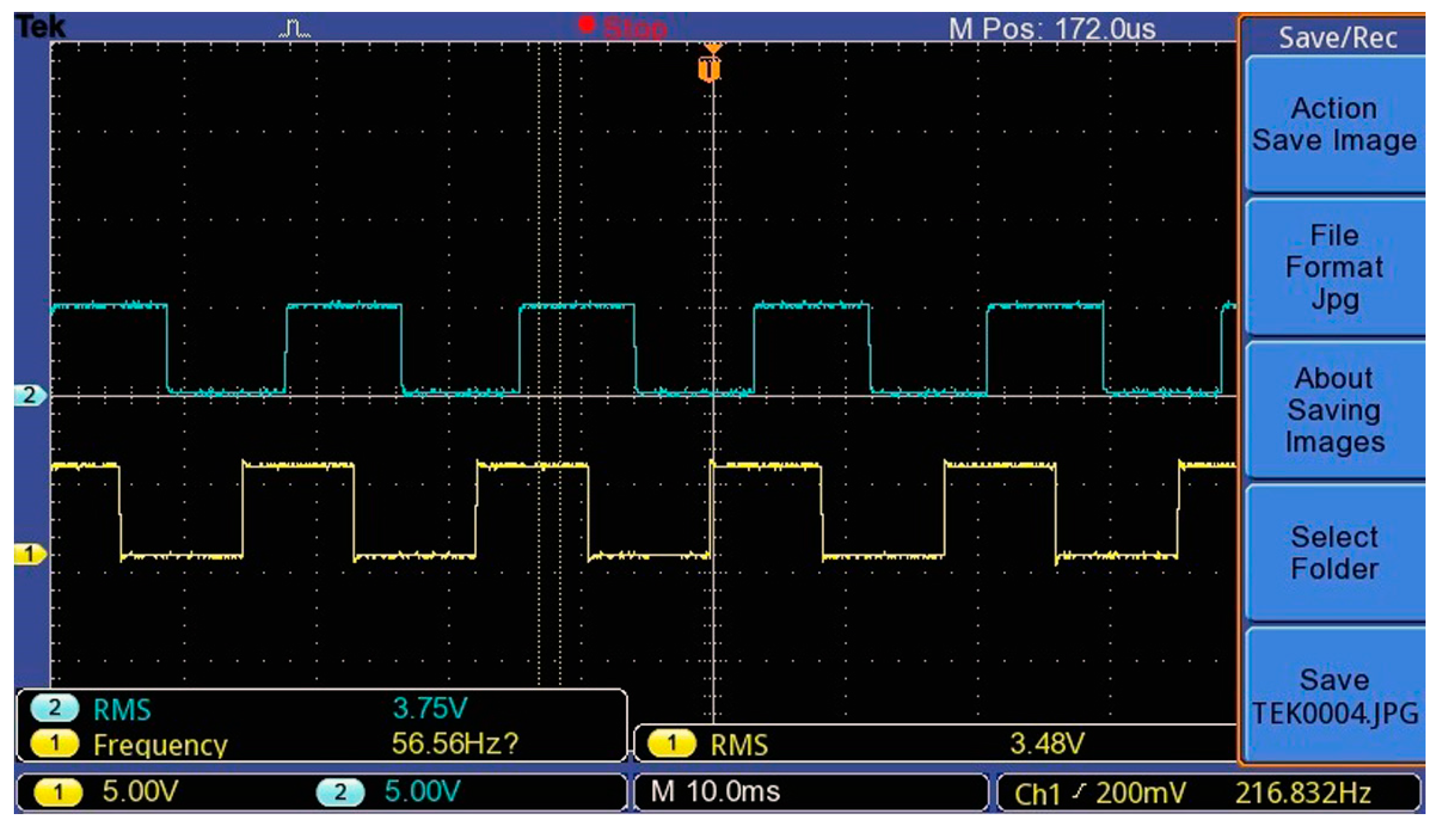
- Hall Sensor Signals
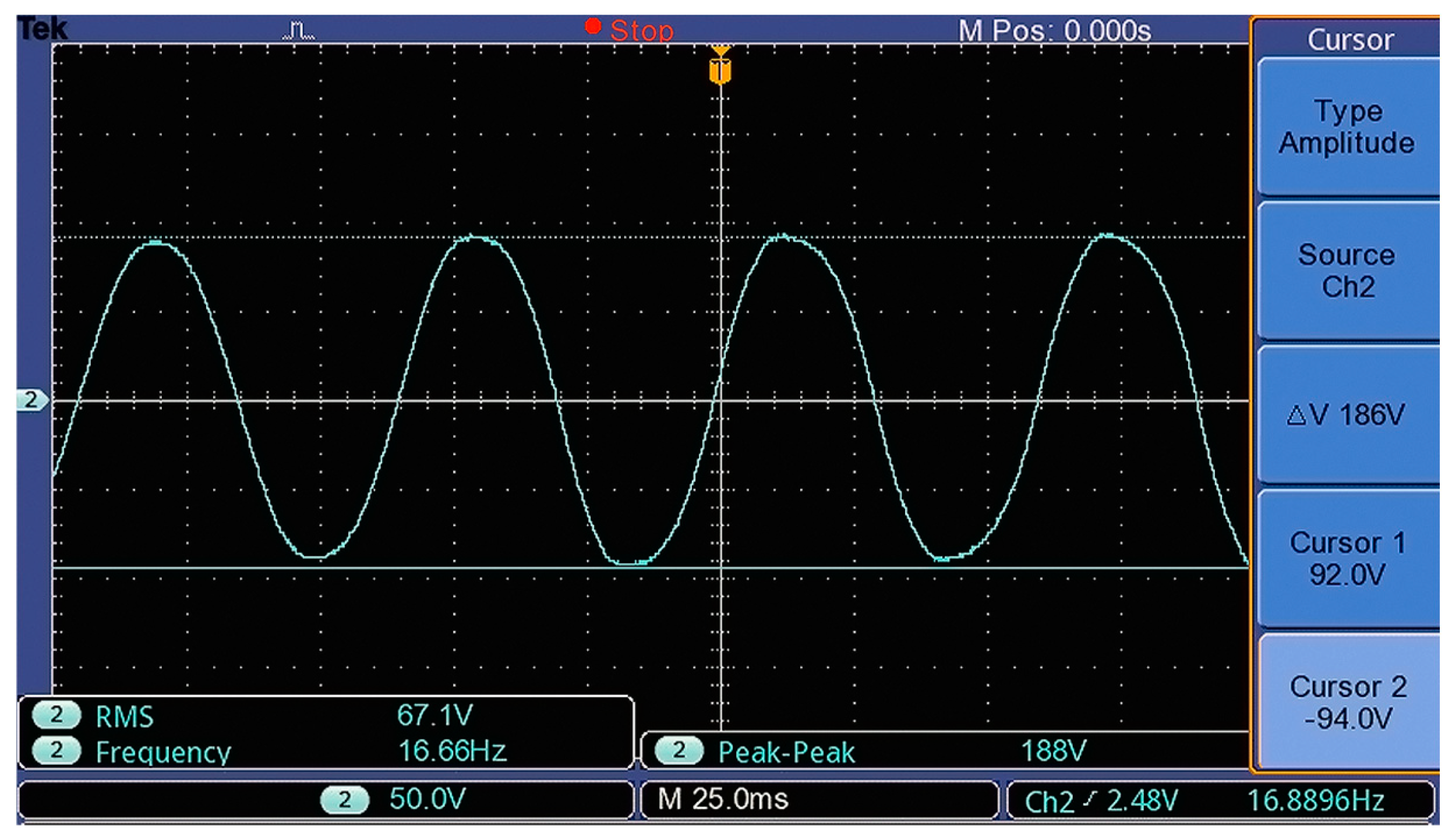
- Back-EMF test result
- (a)
- At 200 RPM
- (b)
- At 150 RPM
- (c)
- At 100 RPM
- (d)
- At 50 RPM
- (e)
- Back-EMF at various rpm values (Phase AB)
- (f)
- Back-EMF at various rpm values (Phase BC)
- (g)
- Back-EMF at various rpm values (Phase AC)
- VFD drive with a three-phase PMSM motor
4. Conclusions
Author Contributions
Funding
Institutional Review Board Statement
Informed Consent Statement
Data Availability Statement
Conflicts of Interest
References
- Rakesh, K.D. Workshop on Brushless Permanent Magnet Design with System Focus; Strategic Technology Group: Pune, India, 2011. [Google Scholar]
- Pillay, P.; Krishnan, R. Modeling, simulation, and analysis of permanent-magnet motor drives. I. The permanent-magnet synchronous motor drive. IEEE Trans. Ind. Appl. 1989, 25, 265–273. [Google Scholar] [CrossRef]
- Mademlis, C.; Margaris, N. Loss minimization in vector-controlled interior permanent-magnet synchronous motor drives. IEEE Trans. Ind. Electron. 2002, 49, 1344–1347. [Google Scholar] [CrossRef]
- Wijenayake, A.H.; Schmidt, P.B. Modeling and analysis of permanent magnet synchronous motor by taking saturation and core loss into account. In Proceedings of the Second International Conference on Power Electronics and Drive Systems, Singapore, 26–29 May 1997. [Google Scholar]
- Morimoto, S.; Tong, Y.; Takeda, Y.; Hirasa, T. Loss minimization control of permanent magnet synchronous motor drives. IEEE Trans. Ind. Electron. 1994, 41, 511–517. [Google Scholar] [CrossRef]
- Seyed, A.; Abolfazal, H.N. Optimal Design and Finite Element Analysis of a High Speed, Axial-Flux Permanent Magnet Synchronous Motor. In Proceedings of the 9th Annual Power Electronics, Drives Systems and Technologies Conference (PEDSTC), Tehran, Iran, 13–15 February 2018. [Google Scholar]
- Neethu, S.; Saumitra, P.; Wankhede, A.K.; Fernandes, B.G. High Speed Coreless Axial Flux Permanent Magnet Motor with Printed Circuit Board Winding. In Proceedings of the International Conference on Electrical Machines and Systems (ICEMS), Jeju, Republic of Korea, 7–10 October 2018. [Google Scholar]
- Hrishikesh, M.; Aishwarya, A.; Swapnil, P.; Vrunda, J. Vector Control of PMSM Using TI’s Launchpad F28069 and MATLAB Embedded Coder with Incremental Build Approach. In Proceedings of the 7th International Conference on Power Systems (ICPS) College of Engineering, Pune, India, 21–23 December 2017. [Google Scholar]
- French, C.D.; Finch, J.W.; Acarnley, P.P. Rapid prototyping of a real time DSP based motor drive controller using Simulink. In Proceedings of the International Conference on Simulation ‘98, York, UK, 30 September–2 October 1998. [Google Scholar]
- Jerčić, T.; Ileš, Š.; Žarko, D.; Matuško, J. Constrained field-oriented control of permanent magnet synchronous machine with field-weakening utilizing a reference governor. Autom. Časopis Autom. Mjer. Elektron. Računarstvo Komun. 2017, 58, 439–449. [Google Scholar] [CrossRef]
- Pei, W.; Zhang, Q.; Li, Y. Efficiency optimization strategy of permanent magnet synchronous motor for electric vehicles based on energy balance. Symmetry 2022, 14, 164. [Google Scholar] [CrossRef]
- Salim, N.; Nikam, S.P.; Pal, S.; Wankhede, A.K.; Fernandes, B.G. Multiphysics analysis of printed circuit board winding for high-speed axial flux permanent magnet motor. IET Electr. Power Appl. 2019, 13, 805–811. [Google Scholar] [CrossRef]
- Wang, X.; Lu, H.; Li, X. Winding Design and Analysis for a Disc-Type Permanent-Magnet Synchronous Motor with a PCB Stator. Energies 2018, 11, 3383. [Google Scholar] [CrossRef]
- Tokgöz, F.; Çakal, G.; Keysan, O. Comparison of PCB winding topologies for axial-flux permanent magnet synchronous machines. IET Electr. Power Appl. 2020, 14, 2577–2586. [Google Scholar] [CrossRef]
- Lai, C.K.; Tsao, Y.T.; Tsai, C.C. Modeling, analysis, and realization of permanent magnet synchronous motor current vector control by MATLAB/simulink and FPGA. Machines 2017, 5, 26. [Google Scholar] [CrossRef]
- Tom, A.M.; Febin Daya, J.L. Machine learning techniques for vector control of permanent magnet synchronous motor drives. Cogent Eng. 2024, 11, 2323813. [Google Scholar] [CrossRef]





| S. No. | Motor Parameters | Values |
|---|---|---|
| 1 | Motor Model name | 2.0 (22 mm) |
| 2 | Motor Rated Amps | 3 A |
| 3 | Motor Poles | 22 |
| 4 | Motor Stator Resistance | 4.47 HMS/phase |
| 5 | Motor Lq Inductance | 64 mH |
| 6 | Motor Ld Inductance | 64 mH |
| 7 | Motor Back-EMF Constant (Ke) | 632.19 V/krpm |
| 8 | Motor Torque Constant (Kt) | 10 N-m/A |
| 9 | Motor Shaft Inertia | 3 Kg m^2 |
| Parameters | Unit |
|---|---|
| Rated Power | 1.5 kW |
| Drive Input Voltage | 415 Volts |
| Drive Frequency | 50 Hz |
| Motor Frequency | 55 Hz |
| Rated RMS Current | 3 Amperes |
| Number of Motor Poles | 22 |
| Back-EMF Type | Sinusoidal |
| Stator Resistance Rs | 4.47 Ohms |
| d-axis Field Resistance Ld | 64 mH |
| q-axis Field Resistance Lq | 64 mH |
| Back-EMF Voltage (Mechanical) Es() | 632.19 V(line-line-RMS/kRPM) |
| Torque Constant | 10.47 Nm/Arms |
| Frequency Reference Upper Limit | 55 Hz |
| Frequency Reference Lower Limit | 1 Hz |
| Carrier Frequency Selection; kHz | 5 KHz |
| 0. To edit parameters, 1. To write protect | 1 |
| To show rpm screen first. | 2 |
| Control Type: 0. V/F Control, 1. V/F + Encoder Control, 2. Space Vector Control | 2 |
| Load Selection: 0. Normal Load, 1. Heavy Load | 1 |
| Source of frequency (rpm) command (Auto): 7. Digital Keypad Dial (Potentiometer) | 7 |
| Source of the frequency (rpm) command (HAND): 0. Digital Keypad | 0 |
| Operation Command (HAND): 0. Digital Keypad Keys, 1. External Switches | 1 |
| Digital Keypad Stop Key: 0. Stop key disable, 1. Stop key enable | 1 |
| Start-up frequency | 0.50 Hz |
| Deceleration time | 40 s |
| Auto acceleration/deceleration setting: 1. Auto acceleration, linear deceleration | 1 |
| Motor selection: 0. Induction motor, 1. SPM, 2. IPM | 1 |
| Rated speed of PMSM | 350 rpm |
| Torque compensation gain | 5 |
| Proportional gain (P) | 1.0 s |
| Integral time (I) | 1.0 s |
| PWM mode selection: 2. Space Vector | 2 |
| Application selection: 0. Disabled, 1. User Parameter, 2. Compressor, 3. Fan, 4. Pump | 3 |
| S.N. | Motor Parameter | Initial Reading | Final Reading |
|---|---|---|---|
| 1 | Motor Shell Temperature (Thermal Gun) | 35 °C | 45 °C |
| 2 | Power Factor | 0.52 | 0.49 |
| 3 | Motor RPM | 350 | 350 |
| 4 | Power (VA) | 953 | 1088 |
| 5 | Power (W) | 522~525 | 526~530 |
| 6 | Motor Voltage (V) | 384~391 | 388~409 |
| 7 | Motor Current (A) | 1.80~2.01 | 1.95 |
| 8 | Input Delta VFD Voltage (Line-Neutral) | 253 | 259 |
| 9 | Input Delta VFD Voltage (Line-Line) | 435 | 444 |
| 10 | Input Current | 1.46~1.59 | 1.50~1.53 |
Disclaimer/Publisher’s Note: The statements, opinions and data contained in all publications are solely those of the individual author(s) and contributor(s) and not of MDPI and/or the editor(s). MDPI and/or the editor(s) disclaim responsibility for any injury to people or property resulting from any ideas, methods, instructions or products referred to in the content. |
© 2024 by the authors. Licensee MDPI, Basel, Switzerland. This article is an open access article distributed under the terms and conditions of the Creative Commons Attribution (CC BY) license (https://creativecommons.org/licenses/by/4.0/).
Share and Cite
Shivarudraswamy, R.; Tangi, S.; Kaup, A. Advancements in PMSM-Based Commercial Fan Control: Hardware, FOC Implementation, and Performance Evaluation. Eng. Proc. 2024, 70, 49. https://doi.org/10.3390/engproc2024070049
Shivarudraswamy R, Tangi S, Kaup A. Advancements in PMSM-Based Commercial Fan Control: Hardware, FOC Implementation, and Performance Evaluation. Engineering Proceedings. 2024; 70(1):49. https://doi.org/10.3390/engproc2024070049
Chicago/Turabian StyleShivarudraswamy, R., Swathi Tangi, and Akshath Kaup. 2024. "Advancements in PMSM-Based Commercial Fan Control: Hardware, FOC Implementation, and Performance Evaluation" Engineering Proceedings 70, no. 1: 49. https://doi.org/10.3390/engproc2024070049
APA StyleShivarudraswamy, R., Tangi, S., & Kaup, A. (2024). Advancements in PMSM-Based Commercial Fan Control: Hardware, FOC Implementation, and Performance Evaluation. Engineering Proceedings, 70(1), 49. https://doi.org/10.3390/engproc2024070049


