
Development of a System for the Active Orientation of Small Screws †


Abstract
1. Introduction
2. Analysis on the Suitability of the Part for Automatic Feeding
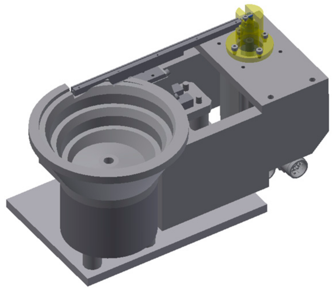
3. Design and Production of the System
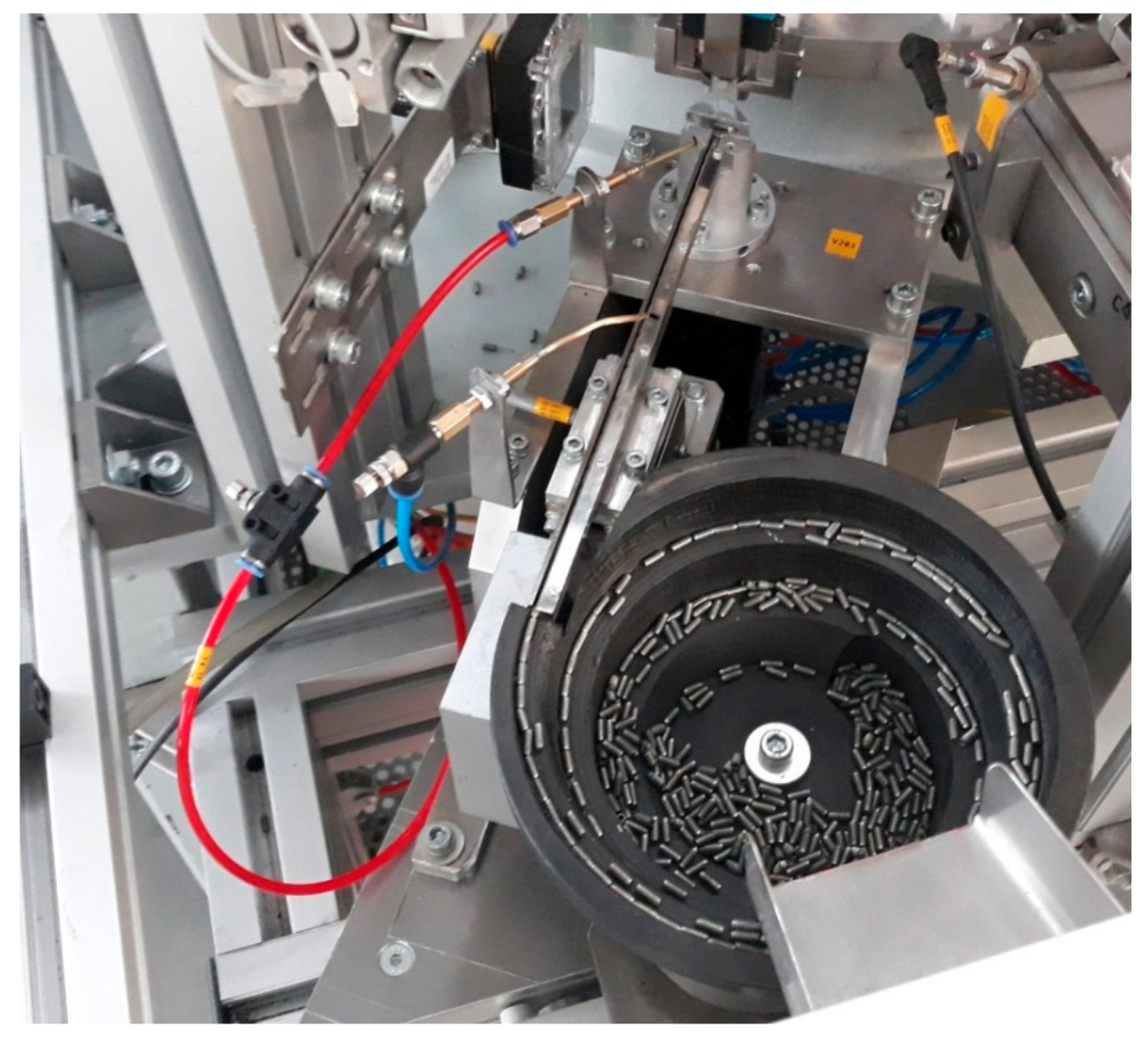
4. Experimental Research
5. Conclusions
Funding
Institutional Review Board Statement
Informed Consent Statement
Data Availability Statement
Conflicts of Interest
References
- Mitev, V.; Malakov, I. Analysis of the quality of polymer parts for automatic assembly. AIP Conf. Proc. 2024, 3063, 060012. [Google Scholar] [CrossRef]
- Mitev, P.; Malakov, I. Development of a system for automatic feeding and orientation of cylindrical parts. AIP Conf. Proc. 2024, 3063, 060017. [Google Scholar] [CrossRef]
- Boothroyd, G. Assembly Automation and Product Design; Taylor & Francis Group: Boca Raton, FL, USA, 2005. [Google Scholar]
- Tang, S.; Zhang, Y.; Jin, Z.; Lu, J.; Li, H.; Yang, J. A Feature-Oriented Reconstruction Method for Surface-Defect Detection on Aluminum Profiles. Appl. Sci. 2024, 14, 386. [Google Scholar] [CrossRef]
- Chakarski, D.; Andonova-Vakarelska, T.; Sarandeva, A. Methodology for design of robotized technological modules for small parts (in Bulgarian). In Proceedings of the NTC for Machine-Building, Sozopol, Bulgaria, 27 June 2000. [Google Scholar]
- Gibson, J.S.K.-L.; Pei, R.; Heller, M.; Medghalchi, S.; Luo, W.; Korte-Kerzel, S. Finding and Characterising Active Slip Systems: A Short Review and Tutorial with Automation Tools. Materials 2021, 14, 407. [Google Scholar] [CrossRef] [PubMed]
- Totev, D.; Dimitrova, R.; Dimitrov, S. Main steps in the process of upgrade of existing systems for automation and control of industrial and manufacturing processes in order to fulfill the requirements of the concept “Industry 4.0”. AIP Conf. Proc. 2024, 3063, 060007. [Google Scholar] [CrossRef]
- Malakov, I.; Zaharinov, V. Choosing an Optimal Size Range of the Product “Pipe Clamp”. In Recent Advances in Soft Computing and Cybernetics; Matoušek, R., Kůdela, J., Eds.; Springer: Cham, Switzerland, 2021; Volume 403, pp. 197–213. ISSN 14349922. [Google Scholar] [CrossRef]
- Malakov, I.; Georgiev, T.; Zaharinov, V.; Tzokev, A.; Tzenov, V. Demand modeling for the optimization of size ranges. In Proceedings of the 26th DAAAM International Symposium, Zadar, Croatia, 18–25 October 2015; Katalinic, B., Ed.; DAAAM International: Vienna, Austria, 2015; pp. 435–444. [Google Scholar] [CrossRef]
- Dichev, D.; Koev, H.; Bakalova, T.; Louda, P. A Kalman Filter-Based Algorithm for Measuring the Parameters of Moving Objects. Meas. Sci. Rev. 2015, 15, 35–43. [Google Scholar] [CrossRef]
- Agrawal, A.; Sun, Y.; Barnwell, J.; Raskar, R. Vision-guided robot system for picking objects by casting shadows. Int. J. Robot. Res. 2010, 29, 155–173. [Google Scholar] [CrossRef]
- Kim, K.; Kim, J.; Kang, S.; Kim, J.; Lee, J. Vision-based bin picking system for industrial robotics applications. In Proceedings of the 9th International Conference on Ubiquitous Robots and Ambient Intelligence (URAI), Daejeon, Republic of Korea, 26–28 November 2012; pp. 515–516. [Google Scholar]
- Oh, J.-K.; Lee, S.; Lee, C.-H. Stereo vision based automation for a bin-picking solution. Int. J. Control Autom. Syst. 2012, 10, 362–373. [Google Scholar] [CrossRef]
- Hou, L.; Liu, Z.; You, J.; Liu, Y.; Xiang, J.; Zhou, J.; Pan, Y. Tomato Sorting System Based on Machine Vision. Electronics 2024, 13, 2114. [Google Scholar] [CrossRef]


| Degree N | Feature | Code |
|---|---|---|
| I | Asymmetry on the external configuration, metal part | 1,000,000 |
| II | The parts do NOT join each other mechanically | 000,000 |
| III | Miniature, ferromagnetic | 60,000 |
| IV | Round, straight | 2000 |
| V | One plane of symmetry | 600 |
| VI | No central hole, non-symmetric ends | 60 |
| VII | Without additional features | 0 |
| Part code number according to the methodology | 1,062,660 |
| # | Parameter | Value | Abbreviation |
|---|---|---|---|
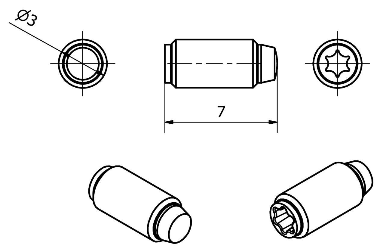
| 1 | Shape | Conical | 2 |
| 2 | Geometry | Almost symmetric | 2 |
| 3 | Material | Metal | М |
| 4 | Mass | Lightweight | 1 |
| 5 | Number of stable states | - | 2 |
| 6 | Color | Single color | М |
| 7 | Additional geometric features | Presence of axial features | 3 |
| 8 | Control features (markings) | No additional information | 3 |
| 9 | Category of application | Electrical components | 7 |
| 10 | Industry | Electrical appliances | 2 |
| 11 | How complex is the part orientation? | Relatively simple | 1 |
| 12 | Design features easing orientation | Without any measures taken in design phase | 1 |
| 13 | Is it possible for the parts to entangle? | The parts do not entangle | 1 |
| 14 | Do the parts have delicate surfaces? | No delicate surfaces | 1 |
| 15 | Are electrostatics an impacting factor? | No influence | 1 |
| Resulting part code | 2 2 M 1 2 M 3 3 7 2 1 1 1 1 1 |
| Trial # | Cone to the Front | Star to the Front |
|---|---|---|
| 1 | 18 | 22 |
| 2 | 22 | 18 |
| 3 | 19 | 21 |
| 4 | 20 | 20 |
| 5 | 24 | 16 |
| MIN | 18 | 16 |
| MAX | 24 | 22 |
| AVG | 20.6 | 19.4 |
Disclaimer/Publisher’s Note: The statements, opinions and data contained in all publications are solely those of the individual author(s) and contributor(s) and not of MDPI and/or the editor(s). MDPI and/or the editor(s) disclaim responsibility for any injury to people or property resulting from any ideas, methods, instructions or products referred to in the content. |
© 2024 by the author. Licensee MDPI, Basel, Switzerland. This article is an open access article distributed under the terms and conditions of the Creative Commons Attribution (CC BY) license (https://creativecommons.org/licenses/by/4.0/).
Share and Cite
Mitev, P. Development of a System for the Active Orientation of Small Screws. Eng. Proc. 2024, 70, 55. https://doi.org/10.3390/engproc2024070055
Mitev P. Development of a System for the Active Orientation of Small Screws. Engineering Proceedings. 2024; 70(1):55. https://doi.org/10.3390/engproc2024070055
Chicago/Turabian StyleMitev, Penko. 2024. "Development of a System for the Active Orientation of Small Screws" Engineering Proceedings 70, no. 1: 55. https://doi.org/10.3390/engproc2024070055
APA StyleMitev, P. (2024). Development of a System for the Active Orientation of Small Screws. Engineering Proceedings, 70(1), 55. https://doi.org/10.3390/engproc2024070055