Proceeding Paper

Development of a Training Station for the Orientation of Dice Parts with Machine Vision †

Faculty of Mechanical Engineering, Mechanical and Instrument Engineering, Technical University of Sofia, Branch Plovdiv, 4000 Plovdiv, Bulgaria
Presented at the International Conference on Electronics, Engineering Physics and Earth Science (EEPES’24), Kavala, Greece, 19–21 June 2024.
Eng. Proc. 2024, 70(1), 57; https://doi.org/10.3390/engproc2024070057
Published: 6 September 2024

Abstract

:
This paper reviews the process of research, development and production of a training station for the optical recognition of dice parts with machine vision. This approach is chosen due to the lack of mechanical features to allow for classical orientation approaches. The embossed dots are about 0.1–0.2 mm deep so it is impossible to design classical traps. The orientation occurs purely by visual comparison to a reference image, part of the current camera job. The sequence of parts is controlled by the programmable logic controller(PLC)program, which manages the camera job-changing process via I/O signals, thus ensuring the right face of the die is captured by the camera and achieving the right predefined order of the sequence. When the preset number of dice in the sequence is reached, they are released back to the vibratory bowl feeder by a pneumatic separator. This way, all dice parts circulate until they are recognized by the camera. There are jobs for each possible orientation of the dice and also a small HMI where the dice sequences could be adjusted by the operator(generally students). The main benefit for the students is the opportunity to program the PLC and to adjust the camera jobs for the detection of each possible orientation. This relies upon the fact that during the fall from the return conveyor to the bowl feeder, the parts flip and, thus, change their previous orientation to another side. Experiments are conducted regarding the probability of obtaining orientation “5” and all the other possible states in order to statistically express the probability.

1. Introduction

The aim of the current paper is to provide information about the research and development of a training station for the optical recognition of dice parts with six faces with a machine vision sensor. The idea behind this station is to build a unit that will help university students experiment with this technology and also with PLC programming since there are many tasks that could be fulfilled during laboratory exercises. The parts are made of plastic, so a careful evaluation of the quality is to be performed [1,2]. This would improve the quality of the automation process. Dice parts are shown in Figure 1 [3].

2. Analysis of the Suitability of the Part for Automatic Feeding

In order to analyze the degree of suitability for automatic feeding, a methodology for quantity assessment, developed in the department of “Automation of discrete production”, is used [4]. The results are shown in Table 1. The die is a part with a complex orientation by means of classic orientation techniques due to the fact that all six sides are mechanically identical if the embossing(the dots) is ignored. Therefore, it is extremely hard if not totally impossible to orient this part by means of classic mechanical orienting mechanisms (traps).
The result is 24, which places the part in category 3, complex parts for automation. According to the algorithm, it is necessary to perform a detailed analysis of the feeding capabilities before designing the system. Preliminary technical and economical calculations are also highly recommended in order to evaluate the potential solution.
The part is also evaluated according to a suggested author classification in Table 2.
In this particular development, the bowl feeder is used for feeding only and no orientation occurs. In most cases, there are classical mechanical orientation devices(traps) that fulfil the orientation process [5,6,7,8]. Taking into consideration the mechanical features and the symmetrical dice part, this is not possible. A more flexible solution is to be found, allowing more control in terms of image-based analysis for decision making rather than using mechanical approaches, which are mainly fixed to a single type of part or parts with a similar shape and/or geometry.

3. Design and Production of the System

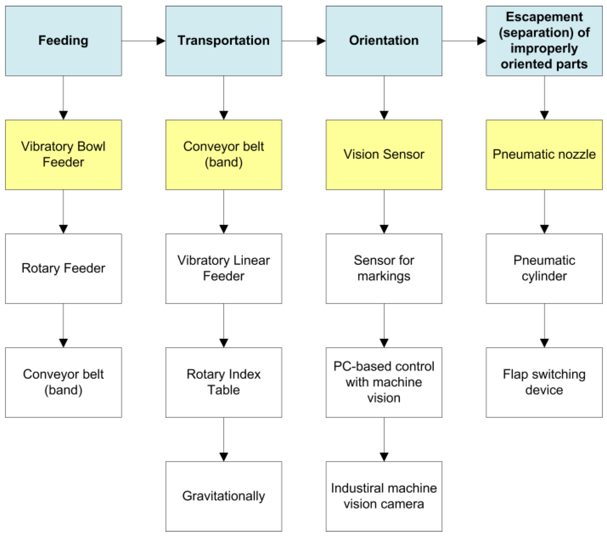
Before the actual design takes place, research on the possible devices that could be used is performed based on the four main tasks that have to be fulfilled—feeding, transportation, orientation and the escapement (separation) of incorrectly oriented parts. A matrix of some of the possible variants for mechatronic devices that could perform the predefined tasks is shown in Figure 2.
Based on the matrix of variants, a particular variant is chosen for each of the categories:
  • Feeding—a bowl feeder since the part is easy for pure feeding (without orientation involved). All part orientations are acceptable and considered correct.
  • Transportation—a belt conveyor is selected in order to reduce the overall number of vibrations in the area of the camera and keep the final solution as simple as possible.
  • Orientation—a machine vision sensor is selected due to its versatility and flexibility (it could be reused for other projects in the university labs with a different mechanical system).
  • Escapement of incorrectly oriented parts—a pneumatic nozzle is selected due to the ease of use and installation below the camera. There is no mechanical impact that is considered positive because there is no contact with the parts and, thus, no wearing on them.
  • At this stage, an additional function is determined—the need for an additional escapement unit (separator) for the correctly oriented parts. When the sequence of five parts is ready, they are released back to a returning conveyor that has an opposite travel direction. A trigger sensor needs to be installed to control the camera picture triggering at the right moment (when a part is passing under the camera).
Figure 3 represents the 3D layout of the system. The work algorithm is as follows: the die is fed into a stainless steel bowl feeder. At the output, it is transferred onto a conveyor belt, and approximately in the middle of this conveyor belt, it is installed a machine vision sensor, triggered by an optical sensor. By each rising edge of the signal, the camera takes an image, processes it and compares it to the currently active job and the respective reference image. If the inspection result is successful, then no further actions are taken, meaning that a die with the currently required orientation is found and it needs to be allowed to continue. However, if the wrong die face is presented to the camera, an output signal is activated, and a pneumatic valve lets air through the nozzle. The die falls onto the second conveyor belt, which returns it to the bowl feeder. Next, when the preset number of parts is arranged in the recognized sequence, the pneumatic cylinder (separator) is released, and these parts are also transferred to the second conveyor to return to the bowl.
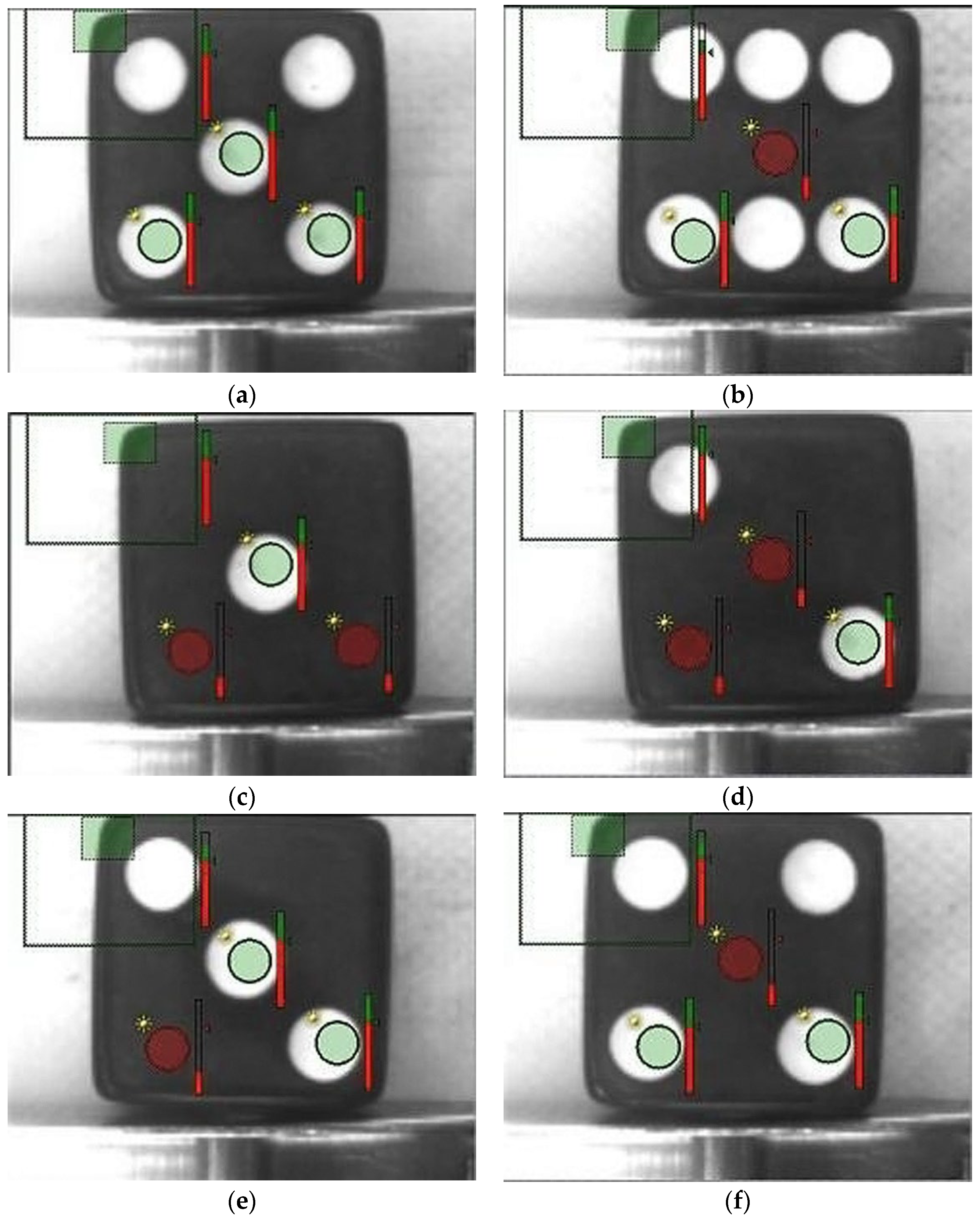
Figure 4 illustrates the setup process of the video sensor for the camera job related to “Face 5”. Here, the approach is to use a brightness sensor in order to detect how many “dots” are there on the surface when the camera is triggered, and an image is taken and analyzed. In addition to the brightness sensors, there is also a part location sensor in the top-left corners of the dice, which allows for variation in the position of the dice along the conveyor band. It is important to note that these sensors are just inspection tools in the camera software and not physical sensors.
A total of three brightness tools is sufficient to recognize face “5” and ensure all other faces are rejected. Face “5” is the only one to have a central dot. However, in order to build a reliable system, additional brightness sensors are also used to inspect two other dots.
These tools have fast execution times, within several milliseconds. The whole image processing is completed within less than 10–15 milliseconds.
As concluded in papers [9,10,11,12], the more general example of the use of machine vision is with the application bin-picking, where there is a bin of unsorted parts, and a robot picks them. This area of research is more complex than what is needed for the current project as all dice parts are perfectly orthogonal to the plane of the vision sensor. Despite the fact that they are moving, the vision sensor is capable of analyzing the image because the frame rate is 100 fps.
As it can be concluded from the images in Figure 4, it is easy to detect Face 5, which is the standard sequence (5,5,5,5,5) only by two points since all other faces lack this combination. The additional brightness tools are for the further improvement of the system. This allows for a more reliable workflow and eliminates random inspection errors. The green circle means that the corresponding brightness tool detects successfully and red means the opposite. The syn symbol simply represents that it is a brightness sensor.
The control system is based on a PLC XINJE XD3-16PRT-C from Xinje Electronics Ltd, Wuxi, China. (shown in Figure 5) [13], which has eight inputs and six outputs. It is freely programmable in the LADDER diagram language as with most PLCs. What is specific about this controller is that C language blocks are also supported and suitable for math algorithms and/or statistical processing. If the machine vision task is only an orientation of the parts according to a specific face, then a PLC would not be necessary.
However, in this project, one of the intentions is to also arrange the parts in a specific sequence (e.g., 1,2,3,4,5) or (5,5,5,5,5). A PLC is needed to change the jobs of the camera (for the detection of all six faces) and to count the number of parts in the ready sequence. As the preset number of parts at the escapement (separator) unit is reached, they are released and returned to the bowl feeder, moving onto the second conveyor belt, which features a reverse direction of movement.

4. Experimental Research

After the system is built mechanically and electrically, detailed experimental research is performed. The first test is related to the probability of taking a specific state of the part, in particular, state “5”. The results from the experiment are shown in Table 3. The test duration for each trial is 5 min.
Additionally, the analysis results in Table 4 are based on more general tests where all states are analyzed. The test batch is always 100 pcs. The experiments have been processed five times in order to achieve more sustainable results, thereby avoiding the influence of various random factors.
Further experiments could be based on the filter-based algorithm in paper [14], taking into consideration the inspection of the dice while moving. A further lab task could be to use measurement tools to perform quality checks of the parts in motion. Optimization methods could be used in other projects where parts with different dimensions are run on the same conveyor belt system [15,16], possibly simultaneously. With additional effort, it is totally possible to build a flexible feeding system that allows multiple parts to be fed at the same time or in sequences, with a quick change-over between them.
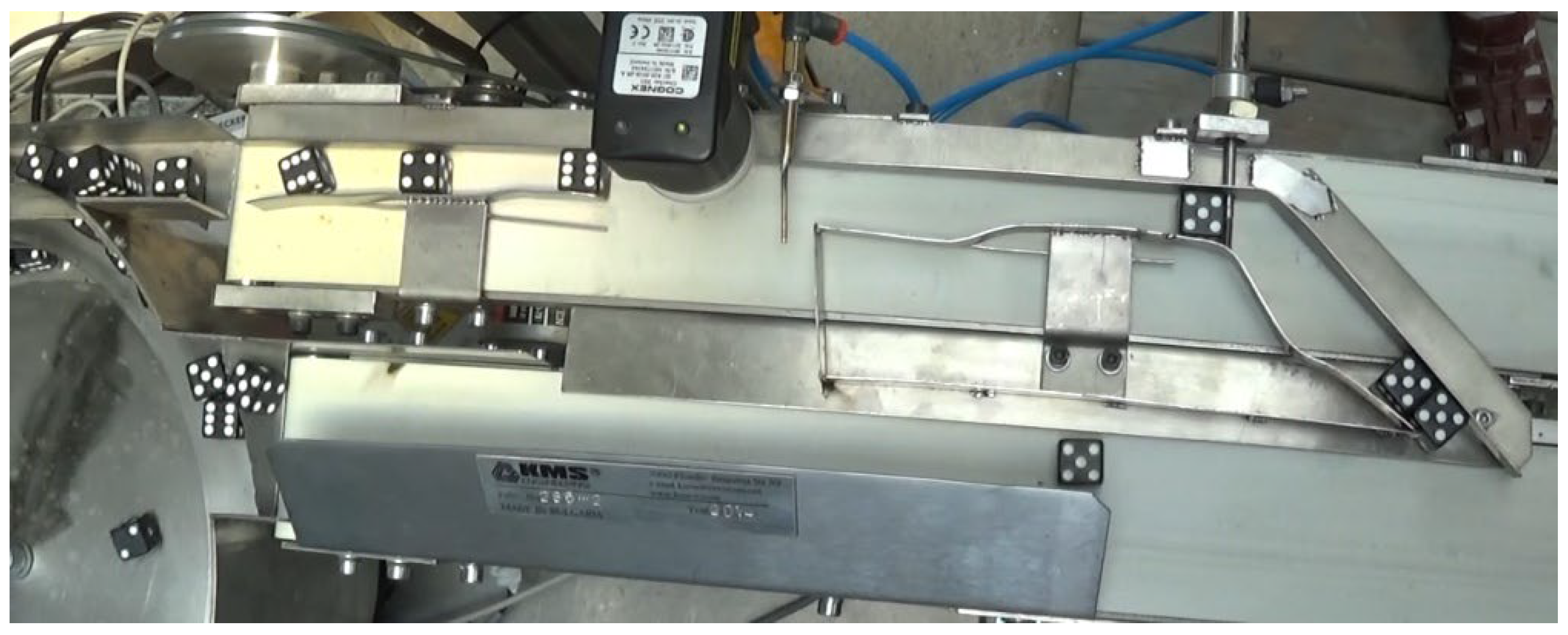
The real developed system is shown in Figure 6. The picture shows the vibratory bowl feeder on the left, which feeds the dice parts towards the input conveyor. Once on the conveyor, the parts are inspected by the camera (Checker 3G1 from Cognex Inc., Natick, MA, USA) (there is a combination of a proximity sensor F&C FF403P/D from F&C Electronics Co Ltd. and a pneumatic nozzle KMS-NOZ-1 (produced by KMS Engineering Ltd., Plovdiv, Bulgaria) for blowing off). The separator is on the right side of the picture, and the pure rod of the pneumatic cylinder is directly used. Using special metal guides, the parts find their way onto the second conveyor and return back to the bowl feeder.

5. Conclusions

This paper follows the process of the development of a flexible mechatronics system that includes mechanical CAD design, PLC programming and machine vision and allows for the training of university students. Furthermore, various experiments and research could be conducted. Based on the methods and results, other types of systems could be developed—for parts inspection, orientation, quality assurance, etc. Machine vision is a popular research area and combined with PLCs, a lot of advanced and complex systems could be developed. Results from this material are applied in solutions for various industries due to the similarity of the used principles.
The future development of this training station may include more flexible changes to the sequence and also some memory of sequences so they can be loaded quickly (recipe functionality).

Funding

The author would like to thank the Research and Development Sector at the Technical University of Sofia for the financial support of this paper.

Institutional Review Board Statement

Not applicable.

Informed Consent Statement

Not applicable.

Data Availability Statement

The obtained data are included in the paper.

Conflicts of Interest

The author declares no conflicts of interest.

References

  1. Mitev, V.; Malakov, I. Analysis of the quality of polymer parts for automatic assembly. AIP Conf. Proc. 2024, 3063, 060012. [Google Scholar] [CrossRef]
  2. Mitev, P.; Malakov, I. Development of a system for automatic feeding and orientation of cylindrical parts. AIP Conf. Proc. 2024, 3063, 060017. [Google Scholar] [CrossRef]
  3. 16 mm Dice-Black. Available online: https://kms-e.de/en/blackdice_16mm/ (accessed on 4 September 2024).
  4. Chakarski, D.; Andonova-Vakarelska, T.; Sarandeva, A. Methodology for design of robotized technological modules for small parts (in Bulgarian). In Proceedings of the NTC for Machine-Building, Sozopol, Bulgaria, 27 June 2000. [Google Scholar]
  5. Boothroyd, G. Assembly Automation and Product Design; Taylor & Francis Group: Boca Raton, FL, USA, 2005. [Google Scholar]
  6. Hesse, S. Rationalisation of Small Workpiece Feeding. Orientating, Sorting, Checking and Feeding; Festo AG & Company: Esslingen am Neckar, Germany, 2000. [Google Scholar]
  7. Bootroyd, G.; Poli, C.R.; Murch, L.E. Handbook of Feeding and Orienting Techniques for Small Parts; Automation Project, Department of Mechanical Engineering, University of Massachusetts: Amherst, MA, USA, 1976. [Google Scholar]
  8. Akella, S.; Mason, M.T. Parts Orienting with Shape Uncertainty. In Proceedings of the IEEE International Conference on Robotics and Automation (ICRA), Leuven, Belgium, 20–20 May 1998; pp. 565–572. [Google Scholar]
  9. Klank, U.; Pangercic, D.; Rusu, R.B.; Beetz, M. Real-time cad model matching for mobile manipulation and grasping. In Proceedings of the International Conference on Humanoid Robots, Paris, France, 7–10 December 2009; pp. 290–296. [Google Scholar]
  10. Agrawal, A.; Sun, Y.; Barnwell, J.; Raskar, R. Vision-guided robot system for picking objects by casting shadows. Int. J. Robot. Res. 2010, 29, 155–173. [Google Scholar] [CrossRef]
  11. Kim, K.; Kim, J.; Kang, S.; Kim, J.; Lee, J. Vision-based bin picking system for industrial robotics applications. In Proceedings of the 9th International Conference on Ubiquitous Robots and Ambient Intelligence (URAI), Daejeon, Republic of Korea, 26–28 November 2012; pp. 515–516. [Google Scholar]
  12. Oh, J.-K.; Lee, S.; Lee, C.-H. Stereo vision based automation for a bin-picking solution. Int. J. Control. Autom. Syst. 2012, 10, 362. [Google Scholar] [CrossRef]
  13. XD3-16/XD5-16. Available online: https://www.xinje-sps.de/de/produkte/sps/xd3-16-xd5-16/ (accessed on 5 February 2024).
  14. Dichev, D.; Koev, H.; Bakalova, T.; Louda, P. A Kalman Filter-Based Algorithm for Measuring the Parameters of Moving Objects. Meas. Sci. Rev. 2015, 15, 35–43. [Google Scholar] [CrossRef]
  15. Malakov, I.; Zaharinov, V. Choosing an Optimal Size Range of the Product “Pipe Clamp”.(Book Chapter). In Recent Advances in Soft Computing and Cybernetics; Matoušek, R., Kůdela, J., Eds.; Springer: Cham, Switzerland, 2021; Volume 403, pp. 197–213. [Google Scholar] [CrossRef]
  16. Malakov, I.; Georgiev, T.; Zaharinov, V.; Tzokev, A.; Tzenov, V. Demand modeling for the optimization of size ranges. In Proceedings of the 26th DAAAM International Symposium, Vienna, Austria, 18–25 October 2015; pp. 435–444. [Google Scholar] [CrossRef]
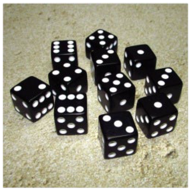
Figure 1. Part picture.
Engproc 70 00057 g001
Figure 2. A matrix of variants.
Engproc 70 00057 g002
Figure 3. The 3D layout of the designed system.
Engproc 70 00057 g003
Figure 4. Inspection of the dice. The following variants are shown: (a) Face 5; (b) Face 6; (c) Face 1; (d) Face 2; (e) Face 3; (f) Face 4.
Engproc 70 00057 g004
Figure 5. PLC XD3-16RT-E.
Engproc 70 00057 g005
Figure 6. Real system.
Engproc 70 00057 g006
Table 1. Application of the methodology on the die part.
Degree NFeatureCode
IAsymmetry on the external configuration, non-metal part2,000,000
IIThe parts do NOT join each other mechanically000,000
IIIEqual dimensions on all sides, non-magnetic90,000
IVNon-round, straight3000
VThree planes of symmetry400
VINo central hole50
VIIA hole, lateral to the main axis0
Part code number according to the methodology2,093,450
Table 2. Part code according to author classification.
#ParameterValueAbbreviation
1ShapeConical2
2GeometryFully symmetric4
3MaterialPlasticP
4MassLightweight2
5Number of stable states-6
6ColourMulti-colourC
7Additional geometrical featuresNo apparent mechanical features for orientation4
8Control features (markings)Parts with additional graphical information (the dots of the dice)1
9Category of applicationOthers8
10IndustryToysT
11How complex is the part orientation?Complex orientation3
12Design features easing orientationWithout any taken measures at design phase1
13Is it possible for the parts to entangle?The parts do not entangle1
14Are the parts with delicate surfaces?No delicate surfaces1
15Is electrostatics an impacting factor?Normal influence by electrostatics2
Table 3. Distribution of the state “5” probability according to trials.
Trial #Number of Parts Taking Position “5” as Top
120
24
312
416
520
616
712
88
920
104
120
Average: 13.2 pcs/5 min
Table 4. Research experiments #1–#5.
Orientation:#1.1#1.2#1.3#1.4#1.5#1.6
Quantity291016131625
Probability (p)0.20.10.160.130.160.25
Orientation:#2.1#2.2#2.3#2.4#2.5#2.6
Quantity221216141620
Probability (p)0.220.120.160.140.160.2
Orientation:#3.1#3.2#3.3#3.4#3.5#3.6
Quantity161613141625
Probability (p)0.160.160.130.140.160.25
Orientation:#4.1#4.2#4.3#4.4#4.5#4.6
Quantity61385117
Probability (p)0.060.130.080.050.110.07
Orientation:#5.1#5.2#5.3#5.4#5.5#5.6
Quantity161418141622
Probability (p)0.160.140.180.140.160.22
Disclaimer/Publisher’s Note: The statements, opinions and data contained in all publications are solely those of the individual author(s) and contributor(s) and not of MDPI and/or the editor(s). MDPI and/or the editor(s) disclaim responsibility for any injury to people or property resulting from any ideas, methods, instructions or products referred to in the content.