Proceeding Paper

Startup Dynamics of Drag-Based Multibladed Vertical Axis Wind Turbine †

School of Engineering, Robert Gordon University, Aberdeen AB10 7GJ, UK
*
Author to whom correspondence should be addressed.
Presented at the 4th Annual Conference Solar And Wind Power, Edinburgh, UK, 4–6 June 2024.
Eng. Proc. 2024, 71(1), 5; https://doi.org/10.3390/engproc2024071005
Published: 29 July 2024

Abstract

:
A multibladed drag-based Vertical Axis Wind Turbine (VAWT) was developed and its startup dynamics evaluated using wind tunnel tests. The experimental data obtained for the time-based angular position of the rotor shaft at Aberdeen’s average wind speed of 6 m/s show an initial rapid acceleration of the VAWT due to the drag force being exerted on the rotor blades. This acceleration becomes more gradual until the VAWT reaches its peak rotational speed of 85 rpm in 30 s, which corresponds to an operating tip speed ratio (TSR) of 0.42. The operating TSR of the VAWT was found to be 27% higher than previously reported in numerical studies.

1. Introduction

Vertical Axis Wind Turbines (VAWTs) are a popular choice to harness wind energy in urban environments where the wind speed and direction are affected by flow re-strictions (buildings, etc.). Due to sudden changes in wind speed and direction, drag-based VAWTs are often preferred as their self-starting capability has been reported to be superior to lift-based VAWTs [1,2]. As drag-based VAWTs come in various different shapes and designs, their startup dynamics are not well reported in the published literature. The few reported investigations are almost exclusively on the conventional S-rotor VAWT [3,4]. However, more modern drag-based VAWT designs have been developed and extensively reported [5]. One such design is the multibladed VAWT [6,7]. Studies carried out on its steady-state performance have reported a higher operating tip speed ratio (λ) and power generation from the multibladed VAWT compared to the S-rotor design [8]. In order to ascertain the commercial viability of the multibladed VAWT, it is of utmost importance to understand and establish its startup dynamics.
In this study, a 12-bladed drag-based VAWT was developed and its startup dynamics evaluated. The VAWT was constructed from sheet metal. Experimental testing was carried out using a subsonic wind tunnel. The results obtained in this study can be used as a ready reckoner before choosing the site for installing multibladed VAWTs. Thus, the outcomes of this study have a direct impact on the commercial viability of small-scale drag-based VAWTs to be used for power generation in urban environments. Moreover, detailed analysis of the startup dynamics are very useful while calculating the Levelized Cost of Electricity (LCoE) from multibladed VAWTs as the capacity factor can be accurately measured rather than predicted.

2. Materials and Methods
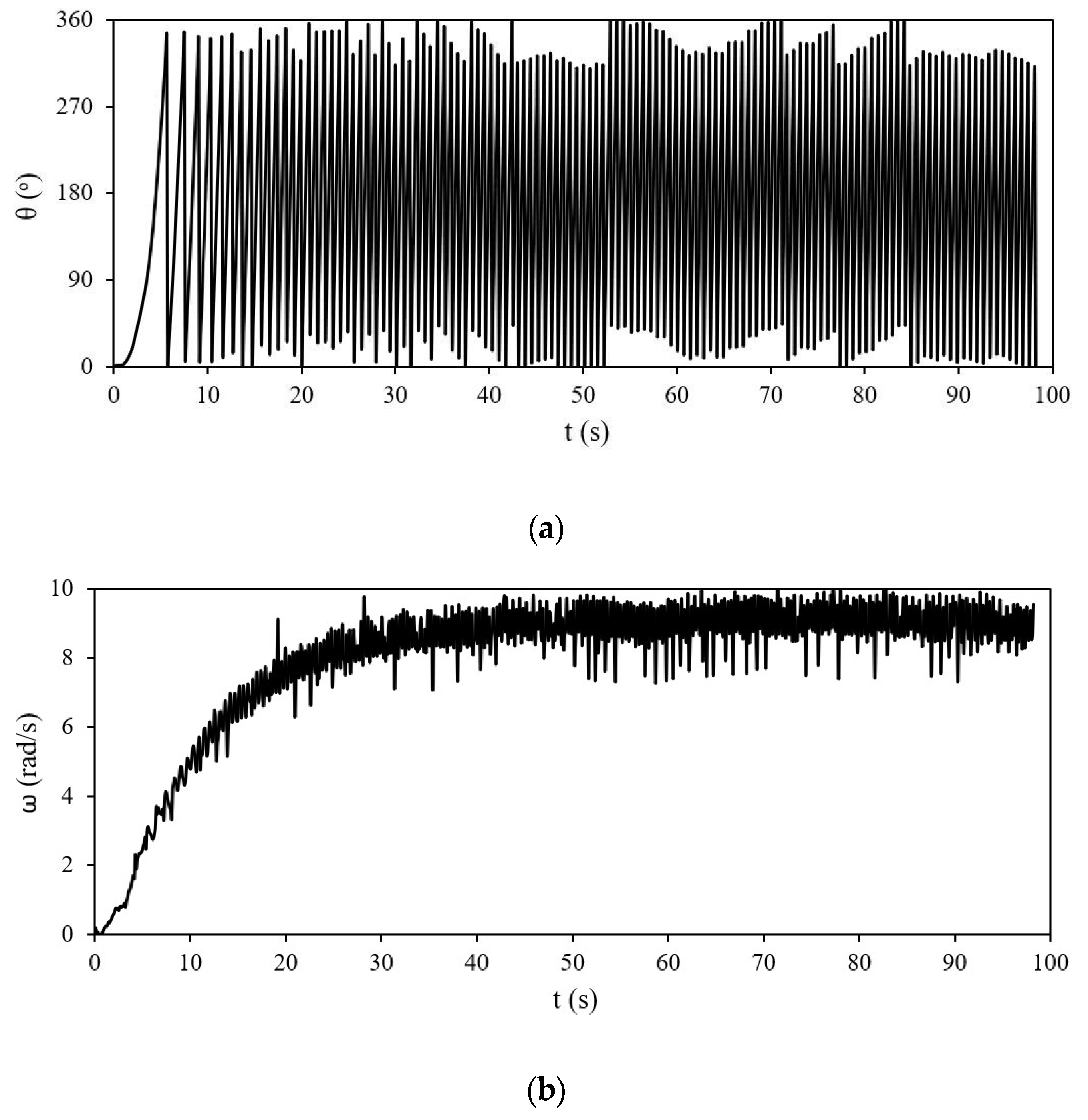
A bespoke test facility was developed in order to achieve the objectives of this study. The test facility consisted of a 1:2.5-scale model of a 12-bladed VAWT and its support structure. The full-scale VAWT was numerically investigated for its steady and transient performance in a number of published studies [6,7]. For experimentation purposes, as we were restricted by the cross-section of the wind tunnel (450 mm × 450 mm), the height of the VAWT was 400 mm, while its inner and outer diameters were 400 mm and 560 mm, respectively. The VAWT was fabricated in-house using 1.6 mm thick cold-rolled aluminum sheets and is shown in Figure 1a. The blades were aerodynamically designed based on velocity triangles as shown in Figure 1b. The portable support structure of the VAWT was made of hollow square aluminum sections of 20 mm × 20 mm and is shown in Figure 1c. A rotary encoder (far right of Figure 1d) was utilized to measure the angular position of the VAWT, exhibiting a frequency of 10 Hz. The encoder was connected to a PC with software installed to record the angular position data with respect to time. The accuracy in measuring the time and angular position of the shaft was 100 ms and 0.05°, respectively. A wind speed of 6 m/s, which is Aberdeen’s average wind speed, was set in the wind tunnel. As for the experimental procedure, the VAWT was held in-place until the desired wind speed was attained from the wind tunnel and verified using a digital manometer. Following this, the VAWT was set free to gain angular momentum until a steady rotational velocity was attained.

3. Results

The data obtained through the use of the test facility is shown in Figure 2. Figure 2a depicts the angular position of the VAWT with respect to time. It can be seen that starting from rest, the VAWT completes its first rotation in 5.6 s. The counter is then adjusted to zero to display the second revolution of the VAWT. The second revolution takes 1.9 s, clearly demonstrating angular acceleration of the VAWT. Similarly, the 3rd revolution is completed in 1.4 s, the 5th in 1.2 s, and so on. It takes almost 30 revolutions of the VAWT until it reaches its stable operational speed and it takes about 30 s to reach there. The missing data between 0° and 360° in this figure are due to the measuring frequency of 10 Hz of the rotary encoder. Figure 2b depicts the rotational speed of the VAWT. It can be seen that as the VAWT starts to rotate, its rotational speed increases with time. The gradient of the curve continues decreasing, indicating a reduction in the angular acceleration of the VAWT. Regardless, the VAWT continues accelerating until about 30 s, when it reaches its peak rotational speed of 9 rad/s. Following this, the VAWT rotates at a constant rotational velocity. Thus, the steady operational speed of this VAWT at 6 m/s wind speed is 9 rad/s.
Further analyzing the experimentally recorded data, the angular velocity (ω) in rpm and the tip speed ratio (λ) were calculated. In order to smooth out the data shown in Figure 2b, a moving average window of 20 counts was used, and the results obtained are shown in Figure 3. It can be seen that the multibladed VAWT reaches a peak angular velocity of 85 rpm in about 30 s. During the startup of the VAWT, the tip speed ratio continues increasing until a peak tip speed ratio of 0.42 is achieved. This clearly indicates that the startup of drag-based VAWTs comprises two stages, i.e., an initial acceleration followed by a plateau region (steady operation). Published studies using numerical methods [6,7] have predicted operational tip speed ratios of 0.33 for the same multibladed VAWT design; however, the experimental investigations of this study clearly show that the actual operational tip speed ratio is 0.42. As the numerical studies are based on a number of assumptions and simplifications like perfectly smooth blades and turbulence modeling, the results presented in this study should be used for calculating the power output and LCOE from multibladed VAWTs.

4. Conclusions

A multibladed VAWT’s startup dynamics are investigated experimentally using wind tunnel testing at Aberdeen’s average wind speed. The results obtained clearly show that when the VAWT starts from rest, air-induced rotation forces it to accelerate, increasing its angular speed and tip speed ratio. This acceleration continues decreasing during the startup of the VAWT. After 30 s of acceleration, the VAWT reaches its peak operational speed of 85 rpm and peak tip speed ratio of 0.42. Thus, the VAWT demonstrates a two-stage startup process. Its measured tip speed ratio is 27% higher than previously reported in studies utilizing numerical methods. With a higher tip speed ratio, the capacity factor of the VAWT is expected to be higher, leading towards more power generation and a reduction in its LCoE.

Author Contributions

Conceptualization, T.A.; methodology, T.A.; formal analysis, T.A.; investigation, T.A.; resources, T.A.; writing—original draft preparation, T.A. and P.O.; writing—review and editing, T.A. and P.O. All authors have read and agreed to the published version of the manuscript.

Funding

This research received no external funding.

Institutional Review Board Statement

Not Applicable.

Informed Consent Statement

Not applicable.

Data Availability Statement

Dataset available on request from the authors.

Conflicts of Interest

The authors declare no conflicts of interest.

References

  1. Mu, Z.; Tong, G.; Xiao, Z.; Deng, Q.; Feng, F.; Li, Y.; Arne, G.V. Study on aerodynamic characteristics of a savonius wind turbine with a modified blade. Energies 2022, 15, 6661. [Google Scholar] [CrossRef]
  2. Zhao, H.; Kang, C.; Ding, K.; Zhang, Y.; Li, B. Transient startup characteristics of a drag-type hydrokinetic turbine rotor. Energy Convers. Manag. 2020, 223, 113287. [Google Scholar] [CrossRef]
  3. Kang, C.; Zhao, H.; Li, B.; Gong, W.; Zhu, Y. Improvement of startup performance of the drag-type hydrokinetic rotor through two-stage configuration. Ocean Eng. 2021, 238, 109677. [Google Scholar] [CrossRef]
  4. Ushiyama, I.; Nagai, H.; Shinoda, J. Experimentally determining the optimum design configuration for savonius rotors. Trans-Actions Jpn. Soc. Mech. Eng. C 1986, 52, 2973–2982. [Google Scholar] [CrossRef]
  5. Mosbahi, M.; Ayadi, A.; Chouaibi, Y.; Driss, Z.; Tucciarelli, T. Performance study of a Helical Savonius hydrokinetic turbine with a new deflector system design. Energy Convers. Manag. 2019, 194, 55–74. [Google Scholar] [CrossRef]
  6. Asim, T.; Singh, D.; Siddiqui, M.S.; McGlinchey, D. Effect of stator blades on the startup dynamics of a vertical axis wind turbine. Energies 2022, 15, 8135. [Google Scholar] [CrossRef]
  7. Asim, T.; Islam, S.Z. Effects of damaged rotor on wake dynamics of vertical axis wind turbines. Energies 2021, 14, 7060. [Google Scholar] [CrossRef]
  8. Zahariev, M.; Asim, T.; Mishra, R.; Nsom, B. Effects of blade tapering on the performance of vertical axis wind turbines analysed through advanced visualization techniques. Int. J. Cond. Monit. Diagn. Eng. Manag. 2019, 22, 69–74. [Google Scholar]
Figure 1. Experimental setup: (a) multibladed VAWT; (b) blade design; (c) VAWT mounted on its support structure; (d) VAWT wind tunnel setup.
Engproc 71 00005 g001
Figure 2. Experimentally recorded data: (a) angular position; (b) rotational speed of the multibladed VAWT.
Engproc 71 00005 g002
Figure 3. Startup characteristics of the multibladed VAWT.
Engproc 71 00005 g003
Disclaimer/Publisher’s Note: The statements, opinions and data contained in all publications are solely those of the individual author(s) and contributor(s) and not of MDPI and/or the editor(s). MDPI and/or the editor(s) disclaim responsibility for any injury to people or property resulting from any ideas, methods, instructions or products referred to in the content.

