
Aero-Servo-Elastic Simulation of the International Energy Agency’s 15MW Reference Wind Turbine for Direct-Drive Generator Integrity Modelling †


Abstract
:1. Introduction
2. Methodology
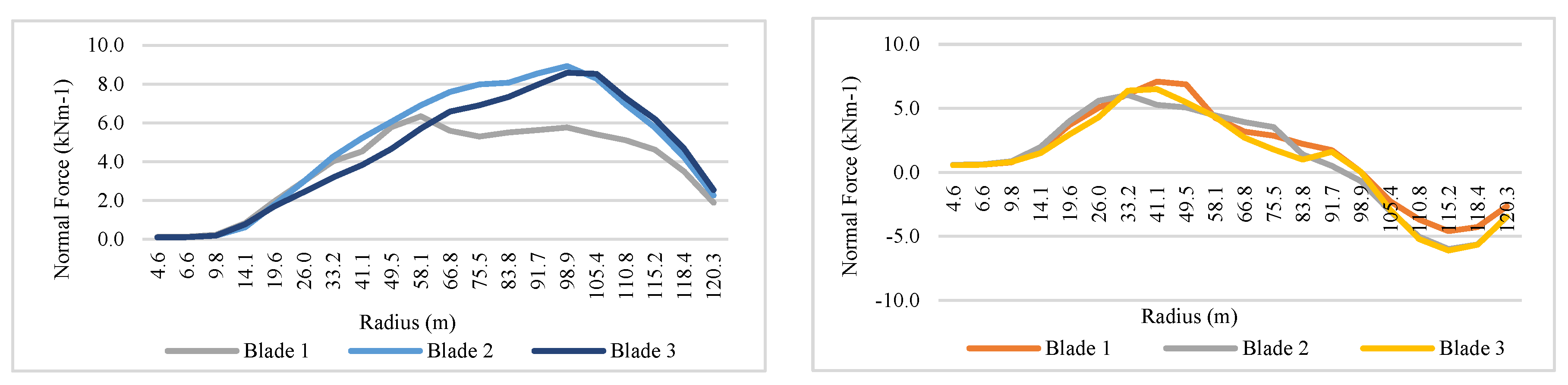
3. Results
4. Discussion and Conclusions
Author Contributions
Funding
Institutional Review Board Statement
Informed Consent Statement
Data Availability Statement
Acknowledgments
Conflicts of Interest
References
- Kaiser, M.J.; Snyder, B.F. Offshore Wind Energy Cost Modeling; Springer: London, UK, 2012; ISBN 9781608054220. [Google Scholar]
- Marten, D.; Saverin, J.; Perez-Becker, S.; Behrens de Luna, R. QBlade CE 2023 (v 2.0.6.4). Available online: https://qblade.org/ (accessed on 10 April 2023).
- Szatkowski, S.; Jaen-Sola, P.; Oterkus, E. An Efficient Computational Analysis and Modelling of Transferred Aerodynamic Loading on Direct-Drive System of 5 MW Wind Turbine and Results Driven Optimisation for a Sustainable Generator Structure. Sustainability 2024, 16, 545. [Google Scholar] [CrossRef]
- Gaertner, E.; Rinker, J.; Sethuraman, L.; Zahle, F.; Anderson, B.; Barter, G.; Abbas, N.; Meng, F.; Bortolotti, P.; Skrzypinski, W.; et al. IEAWindTask37/IEA-15-240-RWT: 15MW Reference Wind Turbine Repository. Available online: https://github.com/IEAWindTask37/IEA-15-240-RWT (accessed on 10 April 2023).
- Gaertner, E.; Rinker, J.; Sethuraman, L.; Zahle, F.; Anderson, B.; Barter, G.; Abbas, N.; Meng, F.; Bortolotti, P.; Skrzypinski, W.; et al. Definition of the IEA 15 MW Offshore Reference Wind Turbine; Golden, CO, USA, 2020. Available online: https://www.nrel.gov/docs/fy20osti/75698.pdf (accessed on 10 April 2023).
- Hansen, M.H.; Henriksen, L.C. Basic DTU Wind Energy Controller; DTU Wind Energy: Roskilde, Denmark, 2013; ISBN 9788792896278. [Google Scholar]
- Allen, C.; Viselli, A.; Dagher, H.; Goupee, A.; Gaertner, E.; Abbas, N.; Hall, M.; Barter, G. Definition of the UMaine VolturnUS-S Reference Platform Developed for the IEA Wind 15-Megawatt Offshore Reference Wind Turbine; Technical Report; U.S. Department of Energy: Oak Ridge, TN, USA, 2020. [Google Scholar] [CrossRef]


| Blade Property | Value | Shaft Property | Value |
|---|---|---|---|
| Length | 117 m | Length | 13.075 m |
| Depth | 1628 mm | Bearing inner (outer) diameter | 2200 (2800) mm |
| Breadth | 4050 mm | Bearing 1 width (effective) | 300 (225) mm |
| Shell thickness | 23.61 mm | Bearing 1 distance to rotor inner face | 433.5 mm |
| Spar width | 25 mm | Bearing 1 axial stiffness | 2.042 × 10¹² Nm−1 |
| Spar cap thickness | 10 mm | Bearing 1 lateral stiffness | 5.695 × 10¹² Nm−1 |
| Spar centroid distance to inside wall | 1334.26 mm | Bearing 2 width (effective) | 470 (352.5) mm |
| Spar cap width | 2700 mm | Bearing 2 distance to rotor inner face | 1548.5 mm |
| Blade root distance to shaft | 3000 mm | Shaft overhang length from Bearing 2 | 7565.32 mm |
| Blade mounting disc diameter | 2000 mm | Bearing 2 axial stiffness | 1.303 × 10¹² Nm−1 |
| Bearing 2 lateral stiffness | 2.320 × 10¹² Nm−1 |
| Structural Analysis Results | −10% | Rated | +10% | High | Unit |
|---|---|---|---|---|---|
| Max. blade displacement | 11.8 | 13.11 | 14.4 | 0.59 | m |
| Max. shaft displacement (Rigid) | 9.368 | 10.411 | 11.449 | 0.325 | mm |
| Max. shaft displacement (Flexible) | 9.372 | 10.413 | 11.455 | 0.325 | mm |
| Max. generator joint displacement (Rigid) | 1.072 | 1.191 | 1.310 | 0.0488 | mm |
| Max. generator joint displacement (Flexible) | 1.074 | 1.193 | 1.312 | 0.0489 | mm |
| Model | Average Tot. Normal Force (N) | Difference (%) | CPU Time (s) | Difference (%) |
|---|---|---|---|---|
| Simplified Onshore | 607,140 | - | 265 | - |
| VolturnUS-S Floating Offshore | 570,085 | −6.5% | 553 | 52.1% |
| Monopile Offshore | 577,571 | −5.1% | 363 | 27.1% |
| Monopile ‘Onshore’ | 585,031 | −3.8% | 407 | 35.0% |
Disclaimer/Publisher’s Note: The statements, opinions and data contained in all publications are solely those of the individual author(s) and contributor(s) and not of MDPI and/or the editor(s). MDPI and/or the editor(s) disclaim responsibility for any injury to people or property resulting from any ideas, methods, instructions or products referred to in the content. |
© 2024 by the authors. Licensee MDPI, Basel, Switzerland. This article is an open access article distributed under the terms and conditions of the Creative Commons Attribution (CC BY) license (https://creativecommons.org/licenses/by/4.0/).
Share and Cite
Bichan, M.; Jaen-Sola, P.; Sellami, N.; Muhammad-Sukki, F. Aero-Servo-Elastic Simulation of the International Energy Agency’s 15MW Reference Wind Turbine for Direct-Drive Generator Integrity Modelling. Eng. Proc. 2024, 71, 8. https://doi.org/10.3390/engproc2024071008
Bichan M, Jaen-Sola P, Sellami N, Muhammad-Sukki F. Aero-Servo-Elastic Simulation of the International Energy Agency’s 15MW Reference Wind Turbine for Direct-Drive Generator Integrity Modelling. Engineering Proceedings. 2024; 71(1):8. https://doi.org/10.3390/engproc2024071008
Chicago/Turabian StyleBichan, Magnus, Pablo Jaen-Sola, Nazmi Sellami, and Firdaus Muhammad-Sukki. 2024. "Aero-Servo-Elastic Simulation of the International Energy Agency’s 15MW Reference Wind Turbine for Direct-Drive Generator Integrity Modelling" Engineering Proceedings 71, no. 1: 8. https://doi.org/10.3390/engproc2024071008