Proceeding Paper

Adaptive Sliding Mode Control of DC–DC Buck Converter with Load Fluctuations for Renewable Energy Systems †

1
Department of Mechanical & Manufacturing Engineering, Pak-Austria Fachhochschule—Institute of Applied Sciences and Technology, Haripur 22621, Pakistan
2
Drive Team, Washing Machine-R&D Center, Beko Corporate, Istanbul 34000, Turkey
3
Department of Electrical Engineering, Riphah International University, Islamabad 44000, Pakistan
4
Department of Mechanical Engineering, Capital University of Science and Technology, Islamabad 44000, Pakistan
*
Author to whom correspondence should be addressed.
Presented at the 4th International Conference on Advances in Mechanical Engineering (ICAME-24), Islamabad, Pakistan, 8 August 2024.
Eng. Proc. 2024, 75(1), 10; https://doi.org/10.3390/engproc2024075010
Published: 23 September 2024

Abstract

:
DC–DC converters are extensively utilized in renewable energy systems because of the flexibility in their output voltage and their good conversion efficiency. The design of an adaptive sliding mode controller is proposed in this paper for a buck converter system in the presence of load variations, power disturbances, and model uncertainties. The adaptive control law is designed based on the Lyapunov stability criterion and updated online according to variations in the load and external disturbances. The elimination of the chattering mechanism and robustness of the overall system is confirmed. Simulation results indicate better voltage regulation and disturbance rejection for the proposed adaptive controller as compared to the traditional control algorithms.

1. Introduction

DC–DC buck converters are extensively utilized in applications including electrical manufacturing, step-down transformers, aerospace, and other related fields [1,2]. In practical applications, the converter is affected by environmental elements, which reduces the efficiency of the converter. These factors include load variations, fluctuations in the input voltage, heating of electronic components, and switch losses. Furthermore, the buck converter has nonlinear characteristics [3]. The major performance requirements of DC–DC buck converters include maintaining a constant output voltage as well as effectively canceling the effects of external disturbances and load variations. Therefore, the improvement of the control system efficiency of the buck converter, as well as minimizing the effects of external disturbances and load variations, is an important topic for the researchers.
Being the traditional control algorithm, the PID control scheme has wide applicability in the industry [4]. However, the PID control scheme is affected by time-varying external interference. Therefore, advanced control techniques including adaptive control [5], a backstepping control scheme [6], and neural network control schemes [7] have been rigorously developed for DC–DC buck converters. However, these control schemes have robustness limitations in the case of strong external disturbances. An adaptive model predictive controller is proposed to counter the parameters’ linear fluctuations in [8]. However, the optimization process becomes more complex by the inclusion of these parameters.
Sliding mode control (SMC) has emerged as a popular control scheme in recent years due to its effective robustness properties against model uncertainties and external disturbances [9]. However, the conventional SMC control scheme has limitations, including finite time convergence issues [10]. A nonlinear sliding surface is proposed in the terminal SMC controller ensuring finite time convergence in [11]. However, finite time convergence is not guaranteed when the states are far from the sliding surface. To make the dynamic output response faster, an integral SMC is proposed in [12]. However, this control approach is only limited to first-order systems.
The aim of this paper is to design an adaptive SMC controller for the DC–DC converter to counter the limitations of the traditional SMC controller. The stability investigation of the suggested scheme is proved utilizing the Lyapunov criterion. The suggested control scheme is capable of eliminating the chattering mechanism and hence ensuring the robustness of the overall system.
The remainder of this article is ordered as given. Section 2 illustrates the analytical modeling of the buck converter. The proposed structure of the adaptive SMC control algorithm is discussed in Section 3. Section 4 consists of results of the buck converter with the proposed control scheme. Conclusions are provided in Section 5.

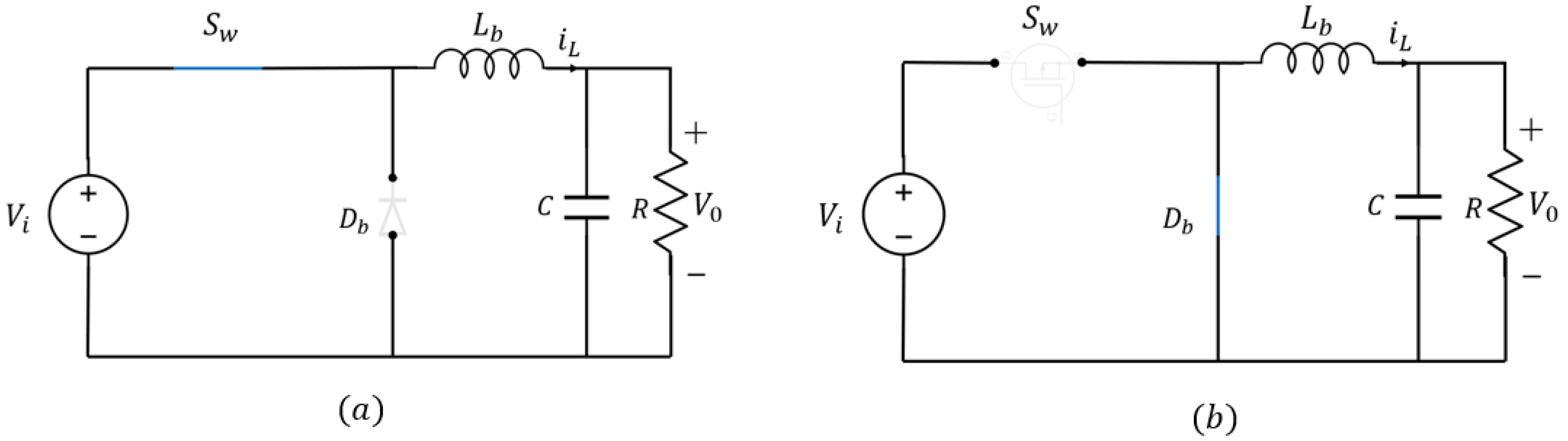
2. Analytical Modeling of Buck Converter

The circuit diagram of the buck converter is illustrated in Figure 1, where V i denotes the input voltage, D b is the diode, L b is the inductor, C represents the filter capacitor, and R is the load.
There are two operational modes for the DC–DC buck converter including CCM, i.e., continuous conduction mode, and DCM, i.e., discontinuous conduction mode.
The dynamics of the converter in CCM mode when the switch is in the on-state as shown in Figure 2a, are given as follows.
L b d i L d t = V i V 0
C d V 0 d t = i L V 0 R
In case the switch is in the off-state as shown in Figure 2b, the dynamics of the buck converter are given as follows.
L b d i L d t = V 0
C d V 0 d t = i L V 0 R
By combining Equations (1) and (2), the following average model of the buck converter in CCM mode is obtained:
d i L d t = 1 L b ( V i d c V 0 )
d V 0 d t = 1 C ( i L V 0 R )
where d c represents the duty cycle of the PWM signal being applied to the switch and has values between 0 and 1. The state variables are chosen as z 1 = V 0 and z 2 = i L / C n , where C n is the nominal parameter value of the capacitor and C n = C + C . Therefore, the following state space model is obtained for the buck converter system:
z ˙ 1 = z 2 + d 1
z ˙ 2 = 1 L n C n z 1 + V i L n C n d c + d 2
where L n represents the nominal inductor value and L b = L n + L . The lumped disturbances d 1 and d 2 are given as d 1 = V 0 R C + i L C i L C n and d 2 = V 0 L C n + V 0 L n C n V i L C n d c V i L n C n d c and both the lumped disturbances are bounded [13].

3. Adaptive Sliding Mode Controller Design
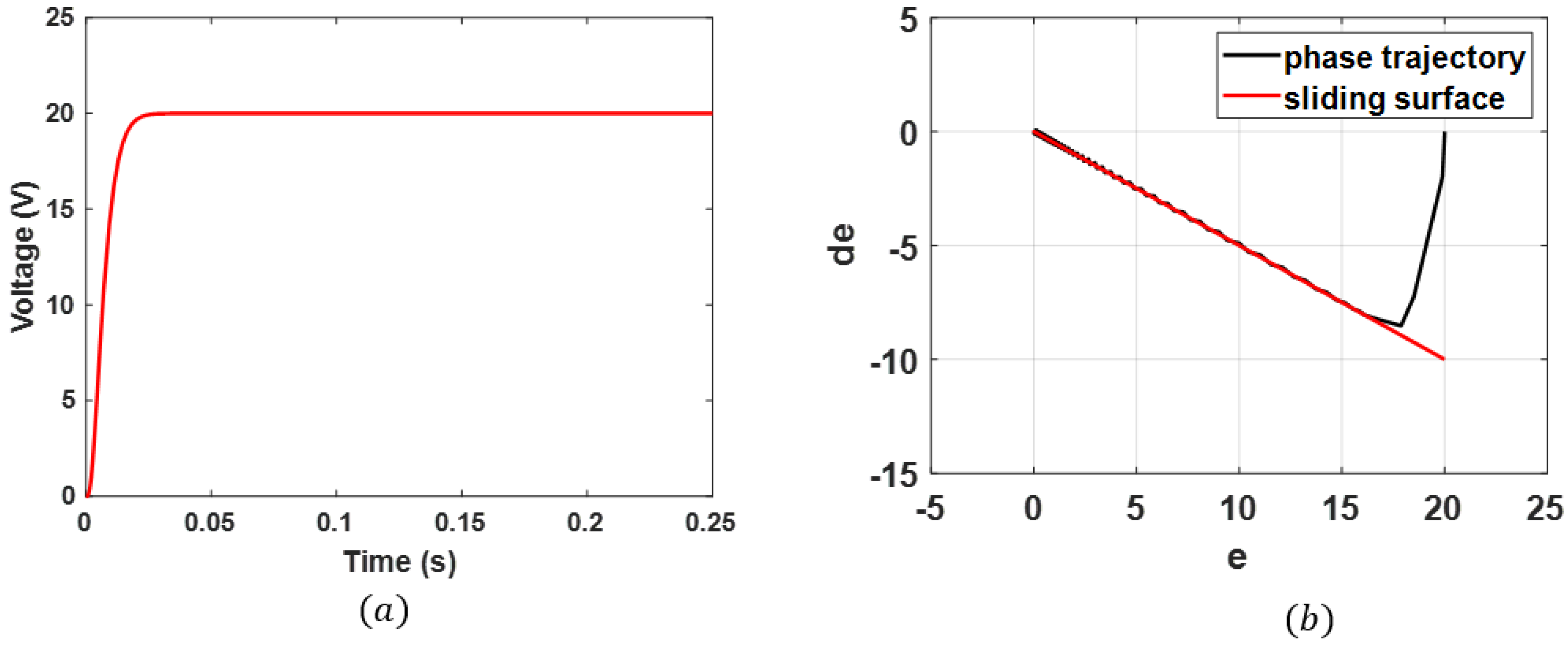
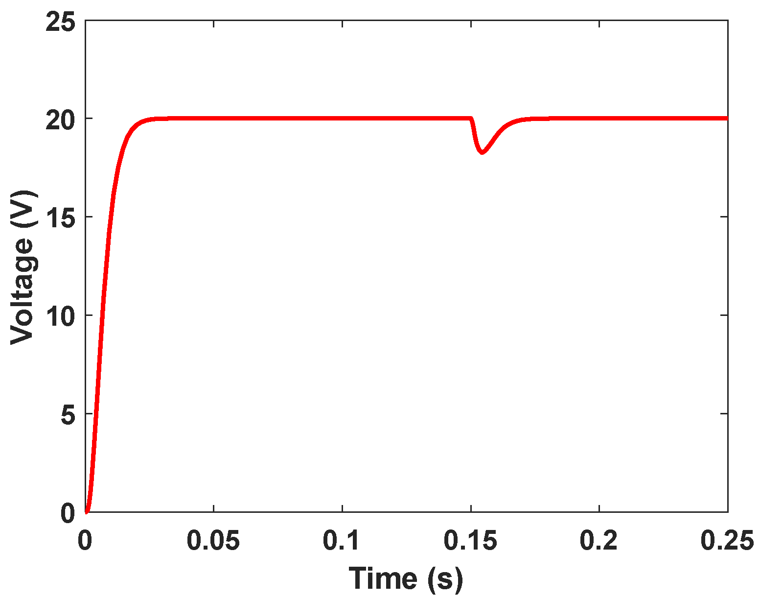
Equation (4) can be re-written as below.
z ˙ 1 = z 2 + d 1
z ˙ 2 = f ( z ) + g ( z ) d c + d 2
The voltage error is defined as e v = v r v 0 .
The sliding mode function is chosen as follows:
s = e ˙ v c e v
where c > 0 . Therefore,
s ˙ = e ¨ v + c e ˙ v = v ¨ r v ¨ 0 + c e ˙ v = v ¨ r f z g z d c d 2 + c e ˙ v
Then, the control law is selected as given below.
d c = 1 g z [ f z + v ¨ r + c e ˙ v + μ s i g n ( s ) ]
Equation (7) can be described as follows.
s ˙ = v ¨ r f z g z d c d 2 + c e ˙ v = μ s i g n s d 2
Therefore, by the selection of μ d 2 , the following condition is obtained.
s s ˙ = η s s d 2 0
For estimating the true value of the system function f z in the presence of disturbances, the radial basis function (RBF) neural network is utilized as follows.
j = e n t c j 2 b j 2
From Equation (9), the system function can be written as below:
f = R T f z + d f
where n t denotes the input of the network, j illustrates the hidden layer nodes of the RBF neural network, R indicates ideal network weights, the output of the Gaussian function is implied by = j T , d f expresses the approximation errors having a range of d f d M , and f characterizes the RBF network’s ideal outputs. The vector n t is selected as x t = e v e ˙ v . The function estimated by the RBF model can be given as follows.
f ^ z = R ^ T f z
Therefore, the input Equation (8) can be written as below.
d c = 1 g z [ f ^ z + v ¨ r + c e ˙ v + μ s i g n ( s ) ]
Equation (7) is re-written as follows:
s ˙ = v ¨ r f f ^ + v ¨ r + c e ˙ + μ s g n s d 2 + c e ˙ = f ~ μ s g n ( s ) d 2
where A ~ = A A ^ = R ~ T f z + d f . The Lyapunov candidate function is chosen as follows:
L = 1 2 s 2 + 1 2 δ R ~ T R ~
where δ > 0 . The derivative of the Lyapunov candidate is given as follows.
L ˙ = s s ˙ + δ R ~ T R ~ ˙ = R ~ T s z + δ R ^ ˙ s ( d f + d 2 + μ s g n s )
The adaptive law is designed as follows.
R ^ ˙ = 1 δ s f z
Therefore,
L ˙ = s d f + d 2 + μ s g n s = s ( d f + d 2 μ s )
As the approximation error d f is small and limited, the condition η d M + d 2 m a x is met and therefore L ˙ 0 is achieved.

4. Results

By the utilization of the proposed algorithm and the system model of the buck converter, a simulation model of the whole system is executed in the presence of load variations and external system disturbances. An RBF structure of 2-5-1 is chosen along with a value of 0.15 for c j and a value of 5 for b j . The parameters’ values for c j and b j are selected on the basis of input value scope by using the gradient descent method. The selection of incorrect parameters’ values for c j and b j will result in the non-convergence of the RBF network. The value of c is selected as 0.5 based on the Hurwitz condition. Choosing too high of a value for the parameter c results in chattering phenomenon. The RBF weight is initialized to 0.15. The input voltage of the buck converter is 24 V and the reference voltage is 20 V. The inductor is 6 mH, load resistance is 20 Ω , and capacitor is 5 μ F. Figure 3a shows the output voltage tracking performance of the proposed adaptive SMC control system. The settling time of the suggested scheme is 14 ms while there is no overshoot present in the output system voltage tracking. The subsequent phase curve of the controller is provided in Figure 3b.
To check the anti-disturbance capability of the designed controller, the load is varied from 20 Ω to 25 Ω at time 0.15 s. The corresponding output voltage profile of the buck converter is shown in Figure 4. The designed controller adaptively canceled the effect of the external load disturbance with a set speed of 17 ms.
Figure 5 shows the performance of the proposed adaptive SMC compared with the traditional SMC controller and the widely utilized PID controller. The settling time in the case of the adaptive SMC controller is 14 ms, while the settling time is 31 ms in the case of the SMC controller and 37 ms in the case of the PID control approach. Overshoot is eliminated in the case of the proposed adaptive SMC controller, while there is a considerable overshoot of 5% in the case of the SMC controller, and 16.7% in the case of the PID controller. Also, the disturbance rejection capability of the proposed controller is much better as compared to that of the traditional SMC controller and the PID controller. The set speed in the case of the proposed adaptive SMC is 19.5 ms, while in the case of the SMC it is 39.5 ms, and in the case of the PID it is 43.7 ms.

5. Conclusions

In this paper, the design of an adaptive SMC controller is elaborated for the DC–DC buck converter based on the Lyapunov stability criterion. The proposed controller adaptively updates the control law based on the effects of the external disturbances and load variations. The chattering phenomenon is eliminated and the overall system stability is ensured. The proposed adaptive SMC controller’s performance is compared with the traditional SMC and the PID controller. The comparison shows better voltage tracking and disturbance rejection performance for the proposed controller.

Author Contributions

Conceptualization, methodology, investigation, data curation, H.S.Z.; writing—original draft preparation, H.S.Z. and A.U.; editing, S.A.H. and Z.Y.; review, A.Z. and M.I. All authors have read and agreed to the published version of the manuscript.

Funding

This research received no external funding.

Institutional Review Board Statement

Not applicable.

Informed Consent Statement

Not applicable.

Data Availability Statement

No new data were created or analyzed in this study. Data sharing is not applicable to this article.

Conflicts of Interest

Author Abasin Ulasyar was employed by the company Beko Corporate, Istanbul, Turkey. The remaining authors declare that the research was conducted in the absence of any commercial or financial relationships that could be construed as a potential conflict of interest.

References

  1. Ibarra, E.; Arias, A.; de Alegría, I.M.; Otero, A.; De Mallac, L. Digital control of multiphase series capacitor buck converter prototype for the powering of HL-LHC inner triplet magnets. IEEE Trans. Ind. Electron. 2021, 69, 10014–10024. [Google Scholar] [CrossRef]
  2. Babes, B.; Mekhilef, S.; Boutaghane, A.; Rahmani, L. Fuzzy approximation-based fractional-order nonsingular terminal sliding mode controller for DC–DC buck converters. IEEE Trans. Power Electron. 2021, 37, 2749–2760. [Google Scholar] [CrossRef]
  3. Malge, S.V.; Patil, S.L.; Deshpande, A.S.; Aher, P.K. Mismatched Disturbance Estimation Based Sliding Mode Control of DC-DC Power Converter. In Proceedings of the 2nd International Conference on Intelligent Technologies (CONIT), Hubli, India, 24–26 June 2022. [Google Scholar]
  4. Alshalalfah, A.L.; Hamad, G.B.; Mohamed, O.A. Towards safe and robust closed-loop artificial pancreas using improved PID-based control strategies. IEEE Trans. Circuits Syst. I Regul. Pap. 2021, 68, 3147–3157. [Google Scholar] [CrossRef]
  5. Jiang, B.; Lu, J.; Liu, Y.; Cao, J. Periodic event-triggered adaptive control for attitude stabilization under input saturation. IEEE Trans. Circuits Syst. I Regul. Pap. 2019, 67, 249–258. [Google Scholar] [CrossRef]
  6. Chi, X.; Lin, F.; Wang, Y.X. Disturbance and uncertainty-immune onboard charging batteries with fuel cell by using equivalent load fuzzy logic estimation-based backstepping sliding-mode control. IEEE Trans. Transp. Electrif. 2021, 7, 1249–1259. [Google Scholar] [CrossRef]
  7. Gheisarnejad, M.; Farsizadeh, H.; Khooban, M.H. A novel nonlinear deep reinforcement learning controller for DC–DC power buck converters. IEEE Trans. Ind. Electron. 2020, 68, 6849–6858. [Google Scholar] [CrossRef]
  8. Albira, M.E.; Zohdy, M.A. Adaptive model predictive control for DC-DC power converters with parameters’ uncertainties. IEEE Access 2021, 9, 135121–135131. [Google Scholar] [CrossRef]
  9. Sheh Zad, H.; Ulasyar, A.; Zohaib, A.; Khattak, A. Adaptive sliding mode predictive power control of three-phase AC/DC converters. Proc. Inst. Mech. Eng. Part I J. Syst. Control. Eng. 2022, 236, 897–912. [Google Scholar] [CrossRef]
  10. Liu, Z.; Lin, X.; Gao, Y.; Xu, R.; Wang, J.; Wang, Y.; Liu, J. Fixed-time sliding mode control for DC/DC buck converters with mismatched uncertainties. IEEE Trans. Circuits Syst. I Regul. Pap. 2022, 70, 472–480. [Google Scholar] [CrossRef]
  11. Mu, C.; He, H. Dynamic behavior of terminal sliding mode control. IEEE Trans. Ind. Electron. 2017, 65, 3480–3490. [Google Scholar] [CrossRef]
  12. Chiu, C.S.; Shen, C.T. Finite-time control of DC–DC buck converters via integral terminal sliding modes. Int. J. Electron. 2012, 99, 643–655. [Google Scholar] [CrossRef]
  13. Wang, Z.; Li, S.; Li, Q. Discrete-time fast terminal sliding mode control design for DC–DC buck converters with mismatched disturbances. IEEE Trans. Ind. Inform. 2019, 16, 1204–1213. [Google Scholar] [CrossRef]
Figure 1. DC–DC buck converter system.
Engproc 75 00010 g001
Figure 2. Buck converter. (a) Switch in on-state. (b) Switch in off-state.
Engproc 75 00010 g002
Figure 3. (a) Output voltage tracking of the buck converter with the proposed controller. (b) The corresponding phase trajectory.
Engproc 75 00010 g003
Figure 4. Output voltage tracking of the buck converter with load disturbance at 0.15 s.
Engproc 75 00010 g004
Figure 5. Performance comparison of the adaptive SMC, the conventional SMC, and the PID controller.
Engproc 75 00010 g005
Disclaimer/Publisher’s Note: The statements, opinions and data contained in all publications are solely those of the individual author(s) and contributor(s) and not of MDPI and/or the editor(s). MDPI and/or the editor(s) disclaim responsibility for any injury to people or property resulting from any ideas, methods, instructions or products referred to in the content.

