Proceeding Paper

Robust & Optimal Predictive Current Control for Bi-Directional DC-DC Converter in Distributed Energy Storage Systems †

1
Department of Mechanical & Manufacturing Engineering, Pak-Austria Fachhochschule: Institute of Applied Sciences and Technology, Haripur 22621, Pakistan
2
Drive Team, Washing Machine-R&D Center, Beko Corporate, Istanbul 34000, Turkey
3
Department of Electrical Engineering, Riphah International University, Islamabad 44000, Pakistan
4
Department of Mechanical Engineering, Capital University of Science and Technology, Islamabad 44000, Pakistan
*
Author to whom correspondence should be addressed.
Presented at the 4th International Conference on Advances in Mechanical Engineering (ICAME-24), Islamabad, Pakistan, 8 August 2024.
Eng. Proc. 2024, 75(1), 26; https://doi.org/10.3390/engproc2024075026
Published: 25 September 2024

Abstract

:
This article proposes the development of an optimal and robust control approach for the voltage regulation of a bi-directional DC-DC converter for its integration in battery energy storage and electric vehicle charging station applications. The objective of the proposed controller is to enhance the robustness and disturbance rejection capability of the bidirectional buck-boost converter. The inner current control loop adopts the optimal model predictive control (MPC) scheme while the outer voltage control loop has been developed utilizing the robust sliding mode control (SMC) approach. The results of the proposed robust & optimal control approach show better voltage conversion capabilities with improved transient response and steady-state characteristics in the presence of variations in load and disturbances.

1. Introduction

The need for renewable energy resources is increasing very rapidly because of the overall increasing demand for electricity, particularly in the transport sector [1]. Electric vehicles (EVs) can support the grid during intervals of peak demand by acting as a source of distributed energy storage. Hence, in this way microgrids could be benefited by having more stability, low peak demands and requirement for low power ratings [2]. Therefore, a bi-directional control approach is required which has the properties of both the robustness and optimal control system. Multiple control approaches have been utilized for controlling the power flow in both the vehicle-to-grid (V2G) and grid-to-vehicle (G2V) system applications. A direct power control method is utilized to select the optimal switching state by the use of a switching table in [3]. Pulse width modulation (PWM) is utilized in traditional voltage-oriented control (VOC) for the purpose of tracking the reactive and active powers [4]. As a result of using the traditional PWM techniques, ripples may be generated in current and power outputs [5]. An application of double integral sliding mode control was introduced for current regulation in bidirectional EV chargers in [6]. However, high frequency noise might be introduced due to the utilization of the pure integrator. In [7], voltage compensation and symmetrical decoupling were employed for controlling a bidirectional converter. However, because of the uncertainties, perfect decoupling of the states is quite challenging. In [8], sliding mode control is employed for the control purpose of an AC/DC converter. However, SMC suffers from the drawback of chattering mechanism. Two cascaded PI controllers have been used to control the voltages and currents in [9]. However, this control mechanism suffers from the drawbacks of initial high overshoot, gains sensitivity and slow response to external disturbances. The direct power control approach is utilized by employing the switching table mechanism for the control of power flow [10,11]. However, this mechanism suffers from frequency variations and power ripples.
Model predictive control is considered as one of the most powerful control approaches for its application in power converters because of multi-objective optimization, capability of dealing with nonlinear systems, and constraint optimization. The optimization is performed by the minimization of the cost function of the discrete time system model [12]. The MPC and active disturbance rejection control (ADRC) schemes are applied in the bidirectional converters because of their good output response [13,14,15]. These techniques usually adopt a single loop control which is relatively easier to design but has the disadvantage of controlling one independent state at a time. Therefore, these controllers cannot simultaneously control the current and voltage of the system. A PI controller is employed with a typical MPC controller for the generation of the current reference for the MPC controller cost function [16]. However, the gains of the PI controller need to be adjusted manually based on the requirements of the system and disturbances. Also, the parameters of the PI controller are fixed during the system’s operation and difficult to tune online as per the load conditions.
This paper proposes the design of a hybrid controller utilizing the benefits of both MPC control and SMC control. The inner current loop utilizes the optimal MPC control approach while the outer voltage loop is controlled by a robust SMC controller to counter the weakness of the PI-based MPC controller for the generation of a reference current signal. The proposed control approach provides faster transient response characteristics and zero steady-state error in the existence of load variations and external disturbances. The principal contribution of this paper is the design of an SMC-based MPC controller for the bidirectional converter to address the shortcomings of PI-based MPC controllers for generating the current reference signal. The generated current reference signal is then utilized by the cost function of the MPC controller. The designed controller’s stability is proven by utilizing the Lyapunov theory. Results indicate the superiority of the proposed approach in the presence of load variations and disturbances.
The remainder of the article is organized as follows. The analytical model of the bi-directional converter is provided in Section 2. Section 3 outlines the design of the proposed control approach utilizing MPC for the current control loop and SMC for generation of current reference signal. Results are provided in Section 4 and the conclusion is given in Section 5.

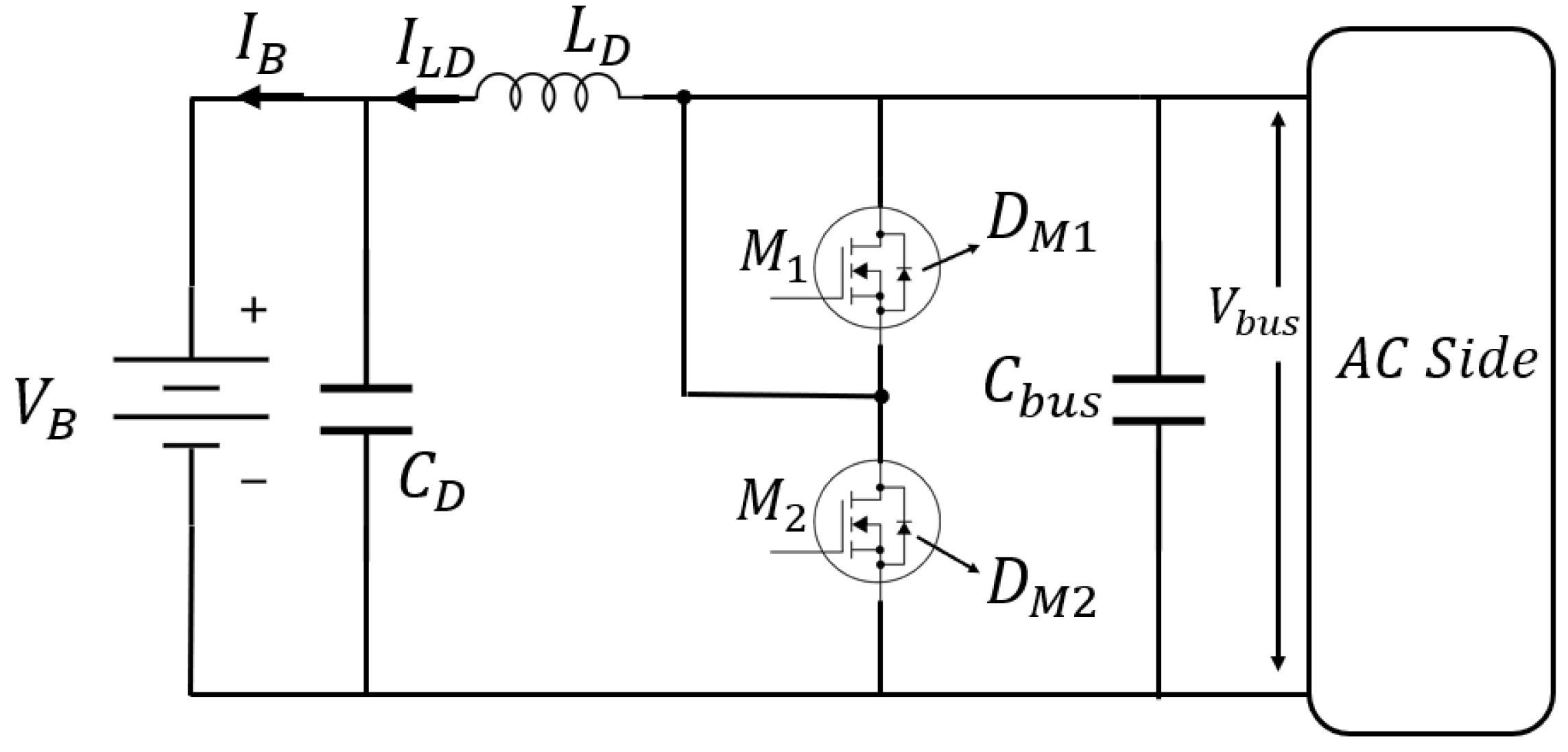
2. Analytical Modeling of Bi-Directional Converter

The schematic diagram of the bi-directional buck-boost converter is given in Figure 1. The circuit consists of an output capacitor C D , two power MOSFETs M 1 and M 2 , filter inductor L D , battery bank V B and a DC bus capacitor C b u s . The two antiparallel diodes M 1 and M 2 are denoted by D M 1 and D M 2 respectively. The given circuit will work in charging mode in G2V configuration and discharging mode in V2G configuration [17].

2.1. Charging Mode of Bi-Directional Converter

The bi-directional converter functions as a buck converter in the charging mode. The overall operation in charging mode can be divided into two stages.
In the first stage, the power MOSFET M 1 is activated while M 2 is turned off. Due to this configuration, the diode D M 2 becomes reverse-biased and the inductor is linearly charged as given below.
V L D = V b u s V B
The inductor current linearly increases and is given as follows.
I L = ( V b u s V B ) / L D
In the second stage, both the MOSFETs are turned off and the conduction is started in the diode D M 2 . The inductor voltage is given as follows.
V L D = V B
The inductor current linearly decreases and is given as follows.
I L = V B / L D
As a result, the filtering inductor current is given as below:
I L D = I B = I * C B ± 1 2 I L D 1
where I * C B is the desired value of the charging current during charging mode and the ripple current is denoted by I L D 1 and given as follows.
I L D 1 = V B ( 1 D ) L D = ( V B V b u s ) D L D

2.2. Discharging Mode of Bi-Directional Converter

The bi-directional converter functions as a boost converter in the discharging mode. The overall operation in discharging mode can be divided into two stages.
In the first stage, the power MOSFET M 2 is activated while M 1 is turned off. Due to this configuration, the filtering inductor voltage is given as below.
V L D = V B
The inductor current linearly increases given as below.
I L = V B / L D
In second stage, both the MOSFETs are turned off and the conduction is started in the diode D M 1 . The inductor voltage is given as follows.
V L D = V b u s V B
The inductor current linearly decreases given as below.
I L = ( V b u s V B ) / L D
In this mode, the bus capacitor C b u s is being charged by the discharging current of the battery bank. The filtering inductor current is given as below:
I L D = I B = I * D B ± 1 2 I L D 2
where I * D B is the desired value of the charging current during discharging mode and the ripple current is denoted by I L D 2 and given as follows.
I L D 2 = V B D L D = ( V b u s V B ) ( 1 D ) L D

3. Design of Robust & Optimal Controller

The inverter unit is connected to the main grid through input inductors L S and resistors R S . The model predictive controller (MPC) is established on the prediction of converter switching vectors at ( n + 1 )th sampling time based on the defined cost function J C . The discrete time rate of change of grid side terminal currents vector I α β in the α β coordinate system is given as follows:
I α β n + 1 I α β n T s = 1 L s ( e α β ( n ) V α β ( n ) R s I α β n )
where e α β represents the three-phase AC voltages in α β reference frame and the vector e α β   consists of e α and e β . Similarly, the inverter terminal voltages in α β reference frame are given by vector V α β . For each switching state k of the three-phase converter, the current is predicted as given below.
I α β n + 1 = T s L s e α β n V α β n R s I α β n + I α β n
The cost function is then chosen as follows for the MPC controller in the α β reference frame:
J C = I α r I α + I β r I β
where I α r and I β r are the reference values of I α and I β , respectively. On every sampling time instant, the cost function is evaluated for all the voltage vectors and then the voltage vector which minimizes the cost function is applied to the converter switches.
During the V2G mode, the d-axis reference current I d r is equal to the ratio of the battery rated power and battery nominal voltage. The d-axis reference current I d r during the mode of G2V is computed using the robust sliding mode controller. The converter instantaneous power is given as follows:
P i n s = V d c 2 R 0 + C D V d c d V d c d t
where V d c is the output voltage and R 0 is the purely resistive load. Therefore, during the steady state, the converter output voltage dynamic equation can be given as follows:
V ˙ d c ( t ) = 1 R 0 C D V d c ( t ) + 3 2 C D u c + d 0
where u c is the control signal and is equal to u c = I d r + ( t ) if ρ ( V d c , t ) > 0 and u c = I d r ( t ) if ρ V d c , t < 0 in the steady state. The term d 0 represents the uncertainties and disturbances in the DC-link voltage. The sliding surface is denoted by ρ ( V d c , t ) and given as below.
ρ V d c , t = e r + κ e r
where e r = V d c t V r , and V r is the reference voltage. Also, κ > 0 is selected based on the output voltage time constant. The speed of output response increases with the reduction in the value of κ . The time derivative of the sliding surface is given as below.
ρ ˙ V d c , t = V d c t V r + κ ( V ˙ d c V ˙ r )
Therefore, the following control action is derived based on Equations (17) and (19).
u c ρ = 2 C D 3 1 κ V r + 1 R 0 C D 1 κ V d c ( δ + ε ) s i g n ( ρ V d c , t )
where the positive constant δ is given as d 0 δ < 1 . The control gain ε is suitably selected such that ε > 0 . Therefore, a suitable control law is obtained based on this adaptation law in the existence of external disturbances and load variations. From Equations (17) and (20), the sliding surface derivative given in Equation (19) can be written as below.
ρ ˙ V d c , t = κ ( δ + ε s i g n ρ V d c , t d 0
The Lyapunov candidate function is selected as below.
L = ρ V d c , t 2 2
Therefore, utilizing Equation (21), the following result is obtained.
L ˙ = ρ V d c , t ρ ˙ V d c , t < 0
Therefore, from Equation (23), the asymptotic stability and robustness of the overall control system is proved with the developed controller.

4. Results

The designed controller is implemented and simulated for the verification of its effectiveness. The filter capacitor used has a value of 680 μF, while the voltage output of the DC side is 200 V. The input inductance L S is 10 mH while the input resistance R S is 0.5 Ω . The switching frequency is 10 kHz and the load resistance is 100 Ω . The value of κ is chosen as 0.5. Figure 2 shows the output voltage profile during V2G response. The settling time is 17 ms with no overshoot. Figure 2b shows the instantaneous grid current and voltage of phase A.
The corresponding FFT signal analysis during G2V is given in Figure 3. The total harmonic distortion (THD) is 3.17%.
The FFT signal analysis during G2V is given in Figure 4 with a THD of 1.83%. The mode of the converter is shifted from V2G to G2V at time t = 4.2 s. The corresponding voltage profile is shown in Figure 5, showing seamless switching amongst the two modes of operation.
The proposed control approach is compared with the PI controller-based voltage control loop and MPC-based inner current loop approach. The resulting output voltage profile for both schemes is shown in Figure 6. The settling time for the proposed control scheme is 17 ms while the settling time for the PI-based MPC controller is 39 ms. Also, the overshoot in the SMC-based MPC controller is eliminated while there is an overshoot of 8.5% in the PI-based MPC controller.

5. Conclusions

In this article, a robust and optimal controller is designed for the voltage regulation of the bi-directional DC-DC converter in the presence of load variations and disturbances. The current loop control has been optimized using the optimal MPC controller while the voltage loop control takes advantage of a robust SMC controller. The efficacy of the suggested control approach is verified by the results of applying the designed controller to the bi-directional DC-DC converter system. Results show better dynamic response and improved THD performance for the designed robust and optimal controller.

Author Contributions

Conceptualization, methodology, investigation, data curation, H.S.Z.; writing original draft preparation, H.S.Z. and A.U.; editing, S.A.H. and Z.Y.; review, A.Z. and M.I. All authors have read and agreed to the published version of the manuscript.

Funding

This research received no external funding.

Institutional Review Board Statement

Not applicable.

Informed Consent Statement

Not applicable.

Data Availability Statement

No new data were created or analyzed in this study.

Conflicts of Interest

The authors declare no conflicts of interest.

References

  1. Un-Noor, F.; Padmanaban, S.; Mihet-Popa, L.; Mollah, M.N.; Hossain, E. A comprehensive study of key electric vehicle (EV) components, technologies, challenges, impacts, and future direction of development. Energies 2017, 10, 1217. [Google Scholar] [CrossRef]
  2. Komurcugil, H.; Bayhan, S.; Guzman, R.; Malinowski, M.; Abu-Rub, H. Advanced Control of Power Converters: Techniques and Matlab/Simulink Implementation; John Wiley & Sons: New York, NY, USA, 2023. [Google Scholar]
  3. Liu, Z.; Miao, S.; Kang, Y.; Fan, Z.; Ye, C.; Li, L.; Chao, K. A bidirectional droop control strategy for the hybrid microgrid with AC/DC distributed generation integration. In Proceedings of the 2018 13th IEEE Conference on Industrial Electronics and Applications (ICIEA), Wuhan, China, 31 May–2 June 2018; IEEE: New York, NY, USA, 2018; pp. 1762–1767. [Google Scholar]
  4. Li, P.; Guo, T.; Pan, Y. An adaptive coordinated constant voltage control method considering power margin for parallel bidirectional power converters in AC/DC hybrid microgrid. In Proceedings of the 2022 IEEE/IAS Industrial and Commercial Power System Asia (I&CPS Asia), Shanghai, China, 8–11 July 2022; IEEE: New York, NY, USA, 2022; pp. 1028–1033. [Google Scholar]
  5. Srivastava, M.; Nama, J.K.; Verma, A.K. An efficient topology for electric vehicle battery charging. In Proceedings of the 2017 IEEE PES Asia-Pacific Power and Energy Engineering Conference (APPEEC), Bangalore, India, 8–10 November 2017; IEEE: New York, NY, USA, 2017; pp. 1–6. [Google Scholar]
  6. Yuan, L.; Li, J. Consensus of discrete-time nonlinear multiagent systems using sliding mode control based on optimal control. IEEE Access 2022, 10, 47275–47283. [Google Scholar] [CrossRef]
  7. Wang, X.; Chen, M.; Li, B.; Zhu, G.; Chen, L.; Sun, X.; Zhang, D.; Hu, J. Control and modulation of a single-phase AC/DC converter with smooth bidirectional mode switching and symmetrical decoupling voltage compensation. IEEE Trans. Power Electron. 2021, 37, 3836–3853. [Google Scholar] [CrossRef]
  8. Jeeranantasin, N.; Nungam, S. Sliding mode control of three-phase AC/DC converters using exponential rate reaching law. J. Syst. Eng. Electron. 2022, 33, 210–221. [Google Scholar] [CrossRef]
  9. Jiao, J.; Meng, R.; Guan, Z.; Ren, C.; Wang, L.; Zhang, B. Grid-connected control strategy for bidirectional ac-dc interlinking converter in ac-dc hybrid microgrid. In Proceedings of the 2019 IEEE 10th International Symposium on Power Electronics for Distributed Generation Systems (PEDG), Xi’an, China, 3–6 June 2019; IEEE: New York, NY, USA, 2019; pp. 341–345. [Google Scholar]
  10. Hu, J.; Zhu, J.; Dorrell, D.G. In-depth study of direct power control strategies for power converters. IET Power Electron. 2014, 7, 1810–1820. [Google Scholar] [CrossRef]
  11. Zhang, Y.; Li, Z.; Zhang, Y.; Xie, W.; Piao, Z.; Hu, C. Performance improvement of direct power control of PWM rectifier with simple calculation. IEEE Trans. Power Electron. 2012, 28, 3428–3437. [Google Scholar] [CrossRef]
  12. Sheh Zad, H.; Ulasyar, A.; Zohaib, A.; Khattak, A. Adaptive sliding mode predictive power control of three-phase AC/DC converters. Proc. Inst. Mech. Eng. Part I J. Syst. Control. Eng. 2022, 236, 897–912. [Google Scholar] [CrossRef]
  13. Sun, K.; Chen, H.; Wu, H.F. A review of analysis method and control technology for isolated bidirectional DC-DC converter used in energy storage systems. Adv. Technol. Electr. Eng. Energy 2019, 38, 1–9. [Google Scholar]
  14. Shan, Y.; Hu, J.; Li, Z.; Guerrero, J.M. A model predictive control for renewable energy based AC microgrids without any PID regulators. IEEE Trans. Power Electron. 2018, 33, 9122–9126. [Google Scholar] [CrossRef]
  15. Shan, Y.; Hu, J.; Chan, K.W.; Fu, Q.; Guerrero, J.M. Model predictive control of bidirectional DC–DC converters and AC/DC interlinking converters—A new control method for PV-wind-battery microgrids. IEEE Trans. Sustain. Energy 2018, 10, 1823–1833. [Google Scholar] [CrossRef]
  16. Antoniewicz, P.; Kazmierkowski, M.P.; Cortes, P.; Rodriguez, J.; Sikorski, A. Predictive direct power control algorithm for three phase AC/DC converter. In Proceedings of the EUROCON 2007-The International Conference on” Computer as a Tool”, Warsaw, Poland, 9–12 September 2007; IEEE: New York, NY, USA, 2007; pp. 1530–1534. [Google Scholar]
  17. Viswanatha, V. Microcontroller based bidirectional buck–boost converter for photo-voltaic power plant. J. Electr. Syst. Inf. Technol. 2018, 5, 745–758. [Google Scholar]
Figure 1. Circuit diagram of the bi-directional converter.
Engproc 75 00026 g001
Figure 2. (a) Output voltage response with the designed robust and optimal controller. (b) The corresponding grid current and voltage for phase A.
Engproc 75 00026 g002
Figure 3. FFT signal analysis during G2V.
Engproc 75 00026 g003
Figure 4. FFT signal analysis during V2G.
Engproc 75 00026 g004
Figure 5. Transition of converter from G2V to V2G at time 4.2 s.
Engproc 75 00026 g005
Figure 6. Comparison of MPC+SMC approach with MPC+PI approach.
Engproc 75 00026 g006
Disclaimer/Publisher’s Note: The statements, opinions and data contained in all publications are solely those of the individual author(s) and contributor(s) and not of MDPI and/or the editor(s). MDPI and/or the editor(s) disclaim responsibility for any injury to people or property resulting from any ideas, methods, instructions or products referred to in the content.

