Proceeding Paper

Melting Performance Enhancement of Latent Heat Thermal Energy Storage Unit by Changing the Angular Orientation †

by
Muhammad Huzaifa
,
Muhammad Haider Ali
,
Muhammad Taha Hashmi
,
Sarmad Ali
*,
Muhammad Mahabat Khan
and
Muhammad Shahid Shafiq
Department of Mechanical Engineering, Capital University of Science and Technology, Islamabad 44000, Pakistan
*
Author to whom correspondence should be addressed.
Presented at the 4th International Conference on Advances in Mechanical Engineering (ICAME-24), Islamabad, Pakistan, 8 August 2024.
Eng. Proc. 2024, 75(1), 29; https://doi.org/10.3390/engproc2024075029
Published: 25 September 2024

Abstract

:
Thermal energy is very crucial, and Phase Change Materials (PCM) provide methods to store it. The objective of this study is to investigate the effect of changing the angle of the Latent Thermal Energy Storage Unit (LTESU) on the amount of time required to melt the PCM. Stearic acid (PCM) was enclosed in a housing to subject it to thermal energy at different orientations. Changing the angle enhances the buoyancy force exerted on melted PCM as thermal energy is added, causing a difference in density. This density difference produces flow currents that circulate the melted PCM in the enclosure due to the hot PCM rising and surrounding the cold PCM that occupies the space left by the hot PCM. These currents are responsible for the distribution of thermal energy throughout the enclosure so that naturally turbulent flow will transfer more heat energy as compared to laminar flow. It was noted that the least amount of time needed to charge the stearic acid was at 60°. An improvement of 16.67% in terms of melting time was observed with respect to the reference case.

1. Introduction

The modern world is in a continuous search of renewable sources of energy as fossil fuels are surely a finite source of energy. A promising solution is thermal energy storage, which uses materials called phase change materials (PCMs). In the study by Zeng et al. [1], changing the orientation can significantly affect the melting time for the PCM, meaning the charge rate is increased or decreased. However, the overall melting rate is lower with an overhead heat source. The study by Webb et al. [2] suggests that change in orientation produces a 3D vortex motion that tends to retard convection patterns as the angle of orientation is increased. In addition to this, if the solid is subcooled initially, it promotes the development of cellular motion. The aim of this study was to find the best possible orientation to achieve the least amount of charge time. According to Peng et al. [3], with the increase inclination angle the rate of charge of the PCM improved significantly. However, it took twice as long for the PCM to solidify. In the study by Allen et al. [4], the number of configurations and case studies that were performed to assess the effects of orientation were 6 and 28, respectively. During melting for the rod-based PCM rig and simple PCM rig configurations, the melting rates may be significantly altered due to the change in natural convection. According to Fakhar et al. [5], the addition of fins improves the transfer of heat to the parts of the PCM where heat doesn’t reach due to buoyancy and vortexes. Additionally, inclining the apparatus yields better results as compared to vertical orientation. According to Mohamed et al. [6], tilting the PCM chamber significantly changes the outcome and increases or decreases the melting time as well as increases or decreases the energy density based on the orientation angle. The orientation in conjunction with the fins produces substantial benefits in the PCM performance with regard to both charge times as well as energy density. According to Safari et al. [7], when regular fins are replaced by bifurcated fins, the performance and the efficiency of the system improves significantly. This improvement can be attributed to the fact that heat transfer is superior and the convection flows are deviated from their regular path by the bifurcations. The downside of bifurcation is that even though the heat transfer surface is increased, the Nusselt number has decreased. Akgün et al. [8] illustrated that instead of using a rectangular chamber with a heated wall, a cylindrical chamber was used where the heating pipe was passed through the center of the cylinder containing the PCM. As the heated water passes through the pipe, it delivers heat to the surrounding PCM, which is met with similar issues as the rectangular chamber. In order to prevent these issues, the apparatus is tilted to improve the flow of free convection, which improves the charging ability of the PCM, hence, improving energy efficiency. Sun et al. [9] emphasize that the PCM in direct contact with the heating plate melts first, which causes the buoyancy to start acting on the melted PCM, which then causes the PCM to pool on top of the PCM chamber while the solid PCM is at the bottom of the chamber. This produces a problem where the heat transferred to the PCM starts to move from one plate to the other through the pool, thereby requiring more energy to be put into the chamber in order for the rest of the PCM to melt. This numerical study by Shafiq et al. [10] examines the effect of different fin designs on the performance of a double-wall-heated TESU with stearic acid as the PCM. Variations in fin angles, shapes, and lengths were analyzed while maintaining constant PCM volume. The results show that configuration-L, with varied lengths and thicknesses of straight fins, significantly enhances the melting performance by 39.5% and the energy storage rate by 65.07%. Additionally, new correlations for the melting Fourier number and average Nusselt number are proposed for optimization across various wall temperatures. Ye et al. [11] present the findings that as the tilt of the PCM chamber increases, the convectional currents also increase. The convectional currents can work in favor as well as against the performance of the PCM, as increasing the charge rate will cause the development of vortices that will hinder the heat-transfer process, thereby reducing the efficiency of the entire system. Therefore, it is recommended to use convectional currents to the PCMs advantage.
To the best of the authors’ knowledge, the problem with the current research performed on PCM is that the studies are performed with only a single source of heat for the PCM. Current work is to investigate the performance enhancement of PCM at different inclination angles with double heated walls, rarely found in literature. The PCM used in this study is stearic acid. Different image-processing techniques and data accusation and processing is used to analyze the melting performance enhancement of the LHTESU.

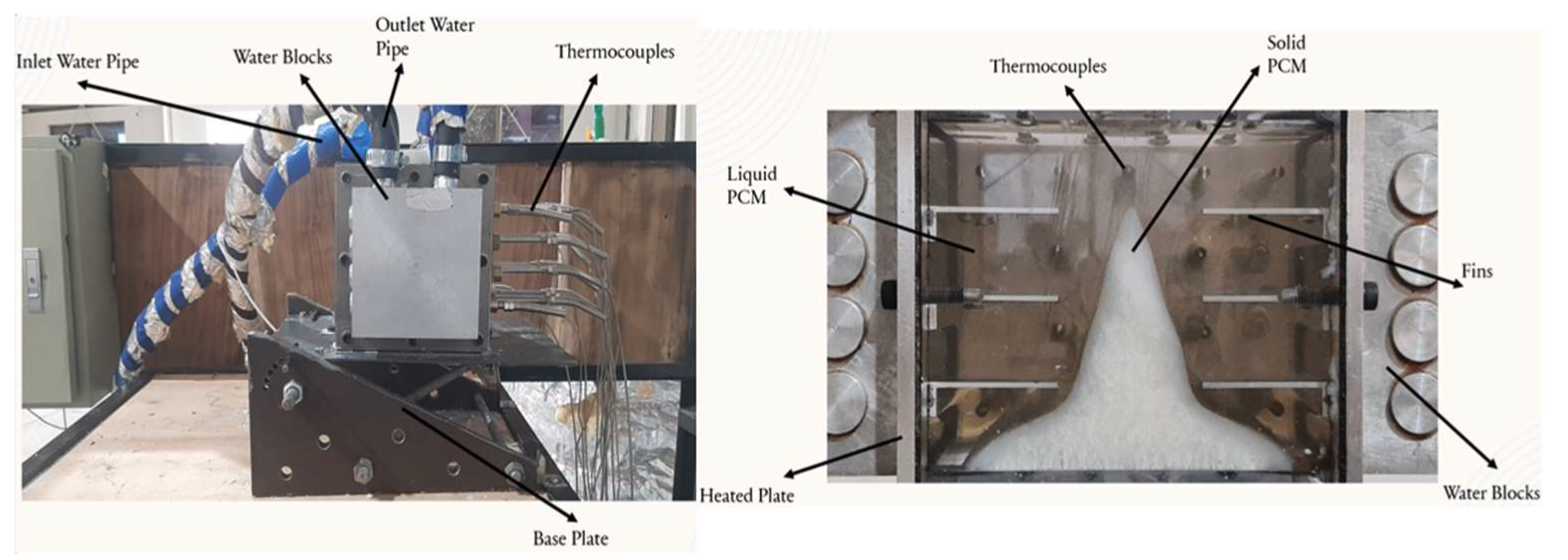
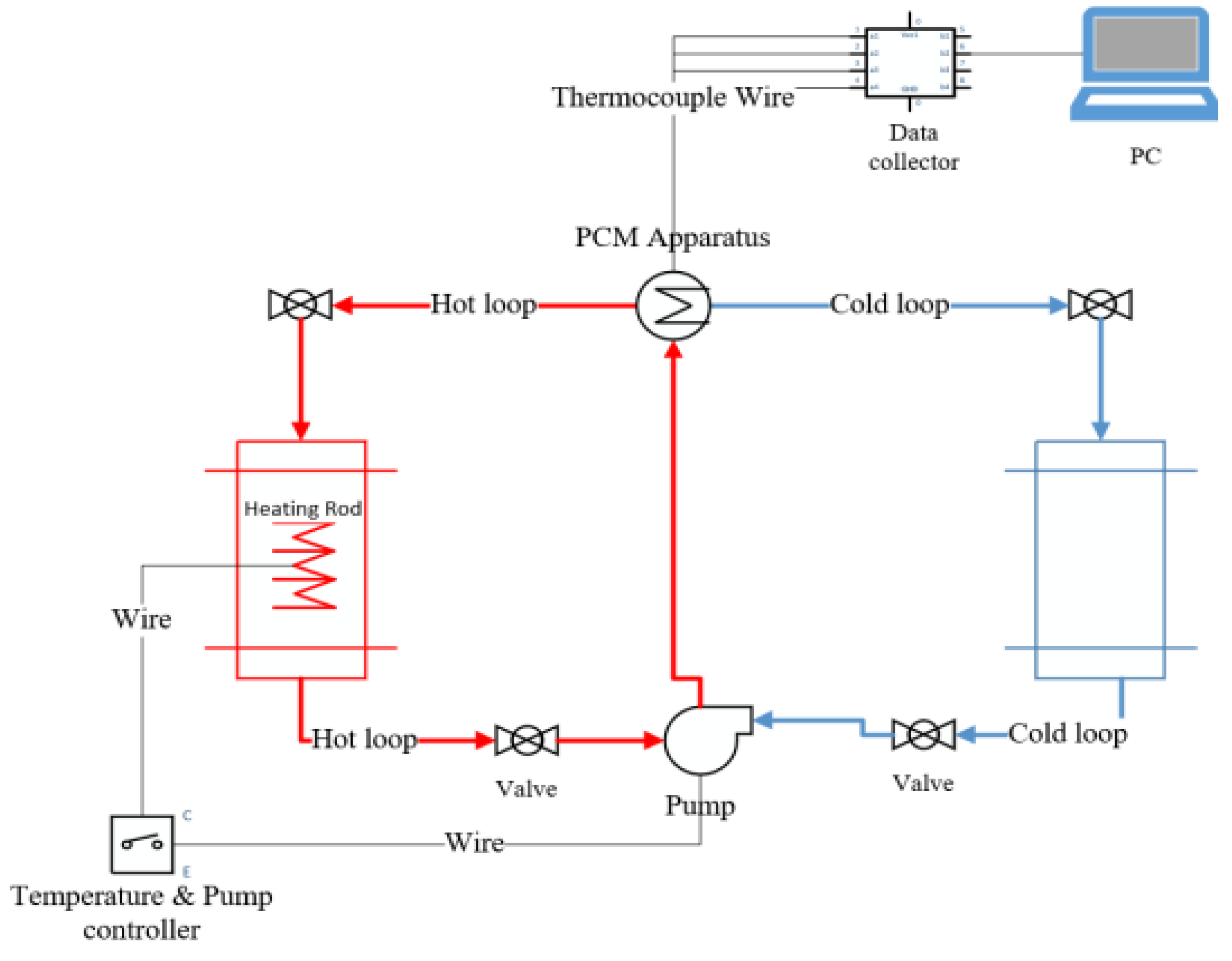
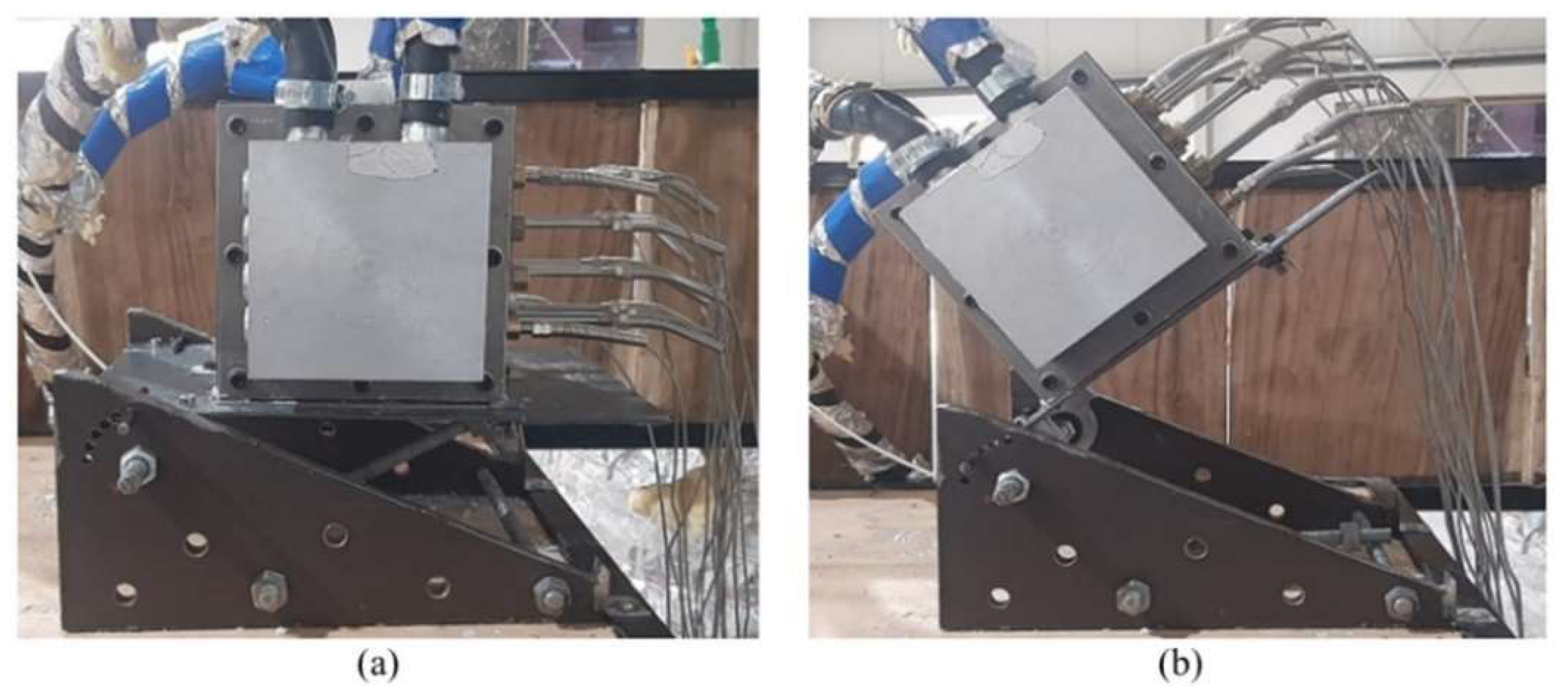
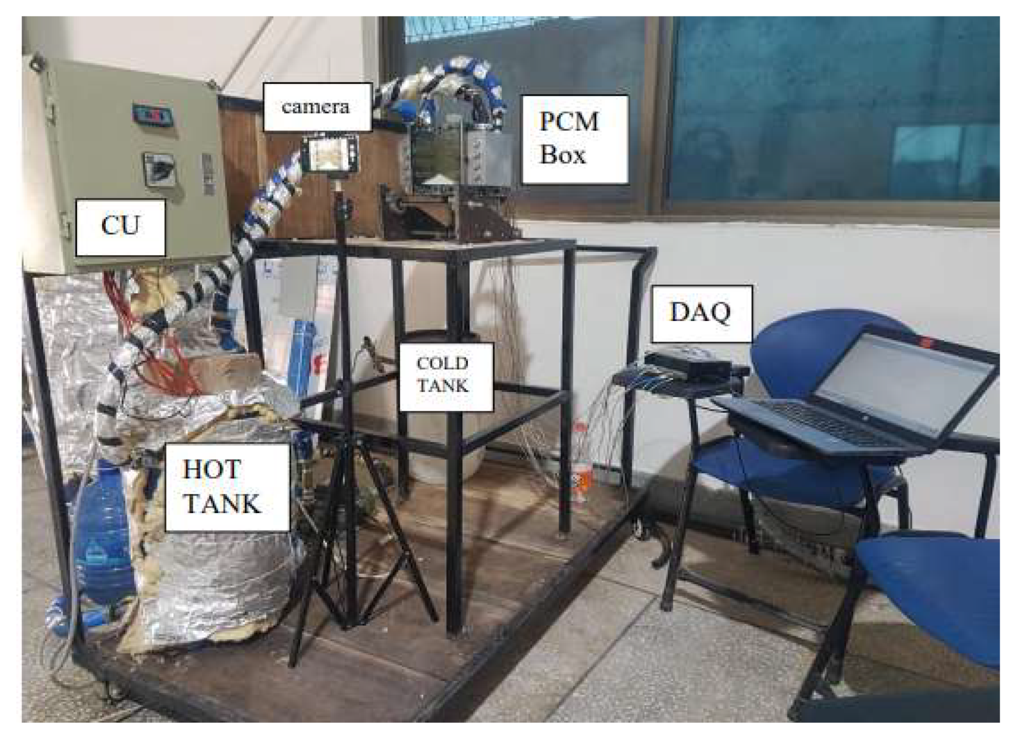
2. Experimental Setup

The experiment involved the use of stearic acid to check different orientations and study the storage of thermal energy. The properties of the PCM are shown in Table 1 [10]. PCM is melted at different angles, and the data is analyzed. Different parts of the experimental setup are shown in Figure 1. The working flow schematics are shown in Figure 2. The thermocouples collect temp. at different positions in the enclosure. The fins allow the heat to penetrate deeper into solid PCM, thereby reducing melting times. Heated water is pumped into and out of the water blocks by the pipes. As the PCM melts, its appearance changes from solid white to yellowish transparent liquid, as shown in Figure 3b. After the PCM has completely melted, the experiment is repeated by changing the orientation angle of the enclosure. The base plate allows the enclosure to be tilted at different angles, as shown in Figure 3.

Experimental Procedure

There is a hot water tank which circulates the hot water through the heat exchangers at 85 °C. In this experiment, the heating source used for water is an electric heating element. However, in an actual scenario, solar energy or waste heat recovery shall be used for water heating. PID controllers and temperature sensors are dipped into the water tub. Sixteen thermocouples are inserted into the PCM box with seals that do not let the melted PCM to leak, and temperatures at different areas are collected. The thermocouples are installed in five columns and five rows for making a complete thermal map of the unit. During experimentation, the temperature readouts are taken after every 2 s, and a picture of the PCM is taken after every 5 min for melt-fraction calculations. First, the image quality was improved and then was used in MATLAB to calculate the instantaneous melt fraction. The data gained from the experiment is stored on the computer by connecting it with a data acquisition unit (DAQ). The schematic and the actual experimental setup is shown in Figure 4.
The data was processed using Equations (1)–(3).
Heat stored Q = mCpΔT
Heat absorbed by solid PCM = q s = ρ s ν s C ps Δ T s
Heat absorbed by liquid PCM = q L = ρ L ν L C pL Δ T L
Total heat absorbed = q t = q s + q L

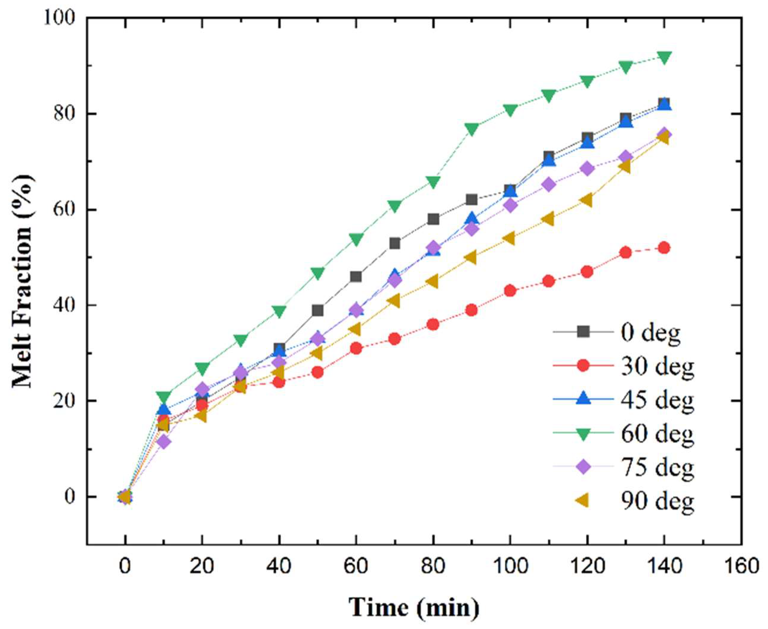
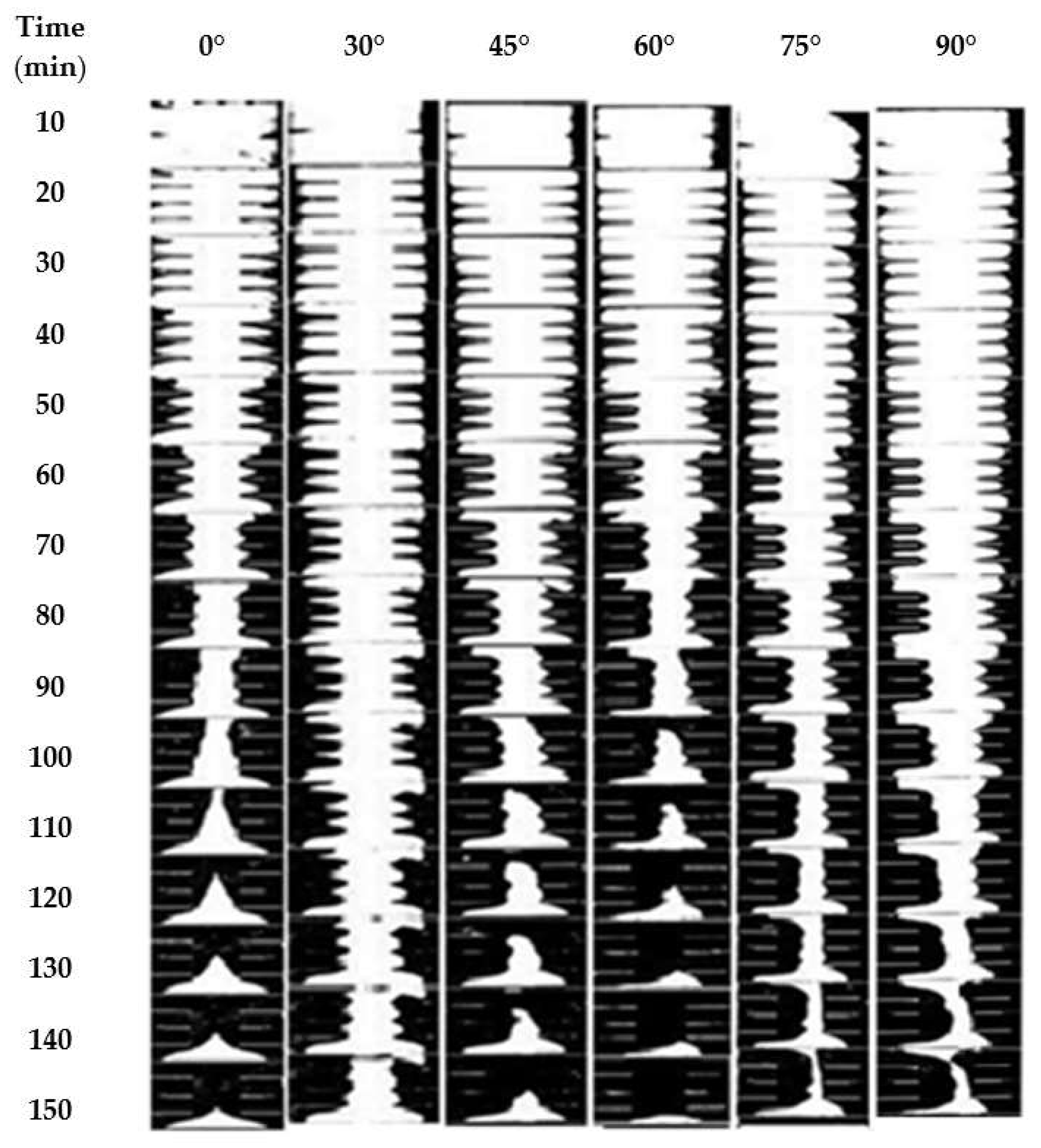
3. Results and Discussion

After collecting data from experiments, different parameters are calculated such as heat transfer rate, buoyancy force, and heat enhancement. Heat transfer is simply the amount of heat needed to melt the PCM completely. Buoyancy force is the upward flow of heated fluid due to convectional currents. Heat enhancement is the improvement of one orientation relative to the 0° orientation.
Figure 5 shows the experimental melt fraction comparison of the different orientations ranging from 0° to 90°. Initially, during the first 10 min of the experiment, the melt fractions vary linearly until the convection currents become dominant due to different tilt angles. It can be clearly seen that the 30° case is the worst-performing case with the least melt fraction of 50% at 140 min. The 90° and 75° cases show similar results, having a melt fraction of 75% at 140 min, which is below the base case 0° tilt angle. The 0° (base case) and 45° case also show similar behavior with a melt fraction of 81.67%. The optimal case at 60° tilt angle shows the highest melt fraction of 92% at 140 min.
Through experimentation, the superior case is highlighted. However, the reason for its improved performance can be understood by observing a key parameter called buoyancy force. As discussed previously, buoyancy force is simply the force experienced by a fluid due to density difference, which is this case is caused by the addition of thermal energy. Firstly, the buoyancy force is plotted by calculating it at equal time intervals for all orientations using the melt fraction and temperatures collected from experiments. The force is plotted on the Y-axis, and the time is plotted on the X-axis. The 60° experiences the highest buoyancy force due to the large amount of heat that is added to the same column, which in turn causes the development of turbulent currents that carry the thermal energy to the PCM that hasn’t melted effectively, decreasing its melting time. This is why, at the 11,600 sec mark in Figure 6, the 60° is not represented as it has completely melted, whereas the 30° & 90° are still in the melting phase.

3.1. Visual Representation of Experimental Melt Fraction

As shown in Figure 7, the binary images taken after every 10 min during the charging cycle of the PCM, the 60° case outperforms other orientations with a significant decrease in total melting time. The worst-performing case, 30°, has the least melting, as shown in the final image. It can be seen that the melting trend declines for cases 30°, 75°, and 90°. However, the base case 0° and 45° stay approxiamtly overlapped in terms of meting when reaching higher melting fractions.

3.2. Uncertainities in Data Acquisition

  • Thermocouples provide average temperatures rather then specific temperatures at different points in the enclosure.
  • All variables are calculated using the temperatures provided by the thermocouples, thereby limiting the validity of the results by a small percentage. The superior method should be to use individual sensors for different variables for instance flow sensors for the verification of laminar or turbulent flow. However, such a setup would increase the cost and complexity of the setup as well as increase its size significantly.

4. Conclusions

The analysis performed showed that orientations that provide the most suitable conditions for buoyancy to occur prove to be the best in terms of performance. The 60° proves to be most effective in decreasing charging times, as one heated plate can directly affect the buoyancy of the opposite plate, depending upon which is higher and which is lower. This leads to convection currents from the lower plate towards the higher plate. The best possible orientation for this specific case is 60°, which outperforms base case of 0° by 16.67%.

Author Contributions

Conceptualization, M.M.K.; methodology, M.S.S., M.H.; software, M.S.S., M.H.A.; validation, M.H.A. and M.H.; formal analysis, S.A., M.S.S. and M.T.H.; investigation, M.H.A. and M.M.K.; resources, M.H. and M.T.H.; data curation, S.A., M.H.A. and M.H.; writing—original draft preparation, S.A., M.H. and M.H.A.; writing—review and editing, S.A., M.H. and M.M.K.; visualization, M.H.A. and M.T.H.; supervision, M.M.K. All authors have read and agreed to the published version of the manuscript.

Funding

This research received no external funding.

Institutional Review Board Statement

Not applicable.

Informed Consent Statement

Not applicable.

Data Availability Statement

Data shall be available on author’s consent.

Acknowledgments

We would like to acknowledge Muhammad Shahid Shafique, an alumnus of Capital University of Science and Technology, for his invaluable help. We are also grateful to Fakhar-ul-Husnain, lecturer at Capital University of Science and Technology, for his help with computational simulations.

Conflicts of Interest

The authors declare no conflicts of interest.

References

  1. Zeng, L.; Lu, J.; Li, Y.; Li, W.; Liu, S.; Zhu, J. Numerical study of the influences of geometry orientation on phase change material’s melting process. Adv. Mech. Eng. 2017, 9, 1687814017720084. [Google Scholar] [CrossRef]
  2. Webb, B.W.; Viskanta, R. Natural-convection-dominated melting heat transfer in an inclined rectangular enclosure. Int. J. Heat Mass Transf. 1986, 29, 183–192. [Google Scholar] [CrossRef]
  3. Peng, L.; Wu, H.; Mao, Q. Visualizing Experimental Study of the Effect of Inclination Angle on the Melting Performance for an Energy Storage Tank. Energies 2022, 15, 7394. [Google Scholar] [CrossRef]
  4. Allen, M.J.; Sharifi, N.; Faghri, A.; Bergman, T.L. Effect of inclination angle during melting and solidification of a phase change material using a combined heat pipe-metal foam or foil configuration. Int. J. Heat Mass Transf. 2015, 80, 767–780. [Google Scholar] [CrossRef]
  5. Hasnain, F.; Irfan, M.; Khan, M. Branching of fins and addition of Al2O3 nanoparticles for rapid charging and discharging of latent heat storage unit. Int. J. Energy Res. 2022, 46, 22625–22640. [Google Scholar] [CrossRef]
  6. Sorour, M.M.; Hassab, M.A.; Zaytoun, M.M.; Alnakeeb, M.A. The effect of inclination angle on the performance characteristic of a double-pipe latent heat storage unit. J. Energy Storage 2021, 34, 102202. [Google Scholar] [CrossRef]
  7. Parsa, N.; Kamkari, B.; Abolghasemi, H. Enhancing thermal performance in shell-and-tube latent heat thermal energy storage units: An experimental and numerical study of shell geometry effects. Int. Commun. Heat Mass Transf. 2024, 154, 107398. [Google Scholar] [CrossRef]
  8. Bott, C.; Dressel, I.; Bayer, P. Paraffin wax as self-sealing insulation material of seasonal sensible heat storage systems-A laboratory study. PLoS ONE 2020, 15, e0236056. [Google Scholar] [CrossRef] [PubMed]
  9. Sun, X.; Zhang, Q.; Medina, M.A.; Lee, K.O. Experimental observations on the heat transfer enhancement caused by natural convection during melting of solid-liquid phase change materials (PCMs). Appl Energy 2016, 162, 1453–1461. [Google Scholar] [CrossRef]
  10. Shafiq, M.S.; Khan, M.M.; Irfan, M. Performance enhancement of double-wall-heated rectangular latent thermal energy storage unit through effective design of fins. Case Stud. Therm. Eng. 2021, 27, 101339. [Google Scholar] [CrossRef]
  11. Kasper, L.; Pernsteiner, D.; Koller, M.; Schirrer, A.; Jakubek, S.; Hofmann, R. Numerical studies on the influence of natural convection under inclination on optimal aluminium proportions and fin spacings in a rectangular aluminium finned latent-heat thermal energy storage. Appl. Therm. Eng. 2021, 190, 116448. [Google Scholar] [CrossRef]
Figure 1. Shows (left) outside of the PCM enclosure (right) inside of the PCM enclosure.
Engproc 75 00029 g001
Figure 2. Schematic diagram of setup.
Engproc 75 00029 g002
Figure 3. Illustrates (a) PCM enclosure at 0° (b) PCM enclosure at 45°.
Engproc 75 00029 g003
Figure 4. Experimental setup.
Engproc 75 00029 g004
Figure 5. Comparison of melt fraction at different angles.
Engproc 75 00029 g005
Figure 6. Comparison of bouyancy force at different angles.
Engproc 75 00029 g006
Figure 7. Melt fraction experimental images at different orientations, from left to right: 0°, 30°, 45°, 60°, 75°, and 90°.
Engproc 75 00029 g007
Table 1. Properties of Stearic Acid [10].
ProperiesValue
Thermal Conductivity, k ( W m 1 K 1 )0.29
Viscosity, µ (kg m 1 s 1 )0.0078
Thermal Expansion Coefficient β ( K 1 )0.00081
Temperature (Solidus, °C)54.5
Temperature (Liquidus, °C)64.1
Density of PCM solid  ρ s   ( k g m 3 ) 1079
Latent Heat of fusion  L f   ( K J k g 1 )  186.5
Specific Heat Capacity (Cp) (kJ/kg.K)2.605
Disclaimer/Publisher’s Note: The statements, opinions and data contained in all publications are solely those of the individual author(s) and contributor(s) and not of MDPI and/or the editor(s). MDPI and/or the editor(s) disclaim responsibility for any injury to people or property resulting from any ideas, methods, instructions or products referred to in the content.

