
VIV-Based Energy Harvesting from Tandem Cylinders for Self-Sustained IoT Systems †


Abstract
1. Introduction
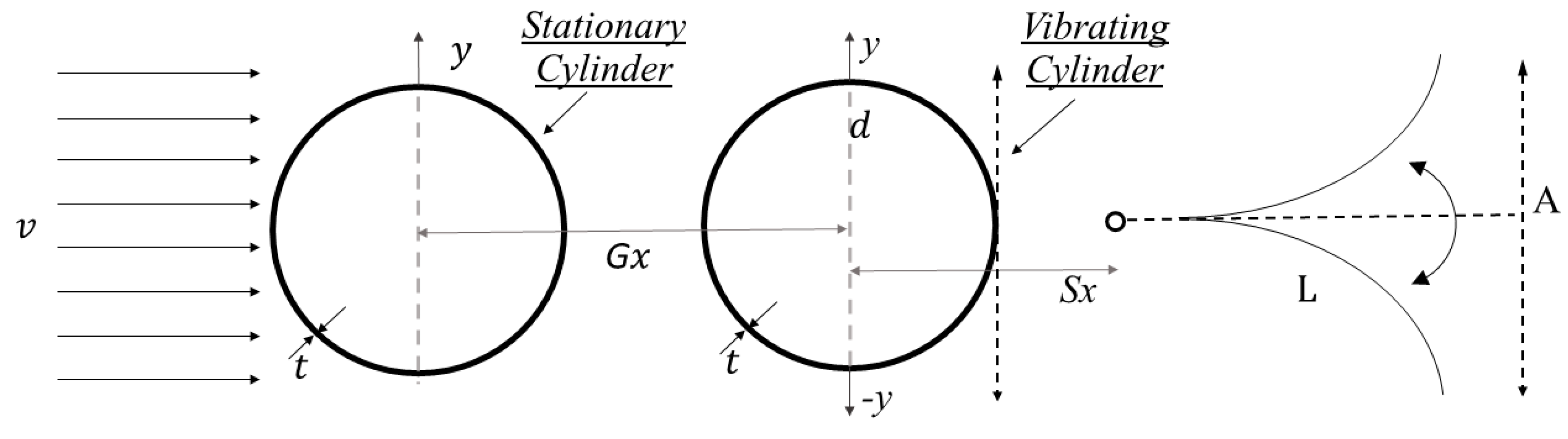
2. Methodology
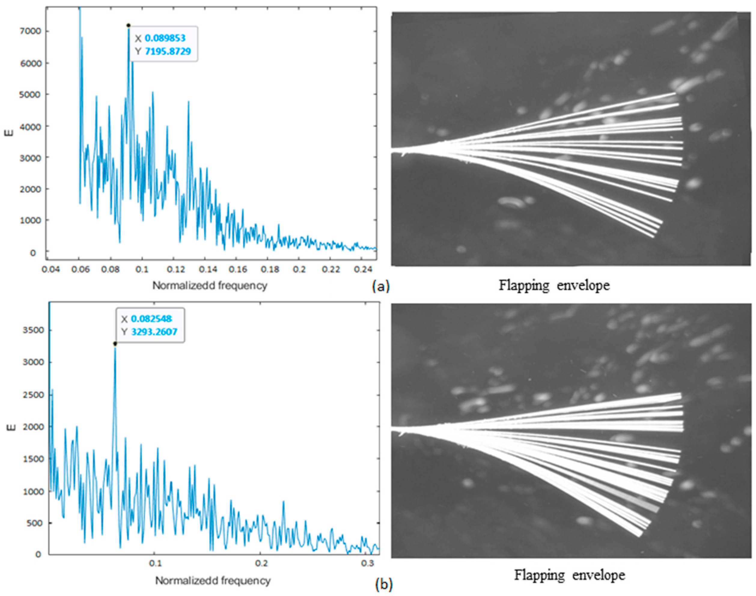
3. Results and Discussion
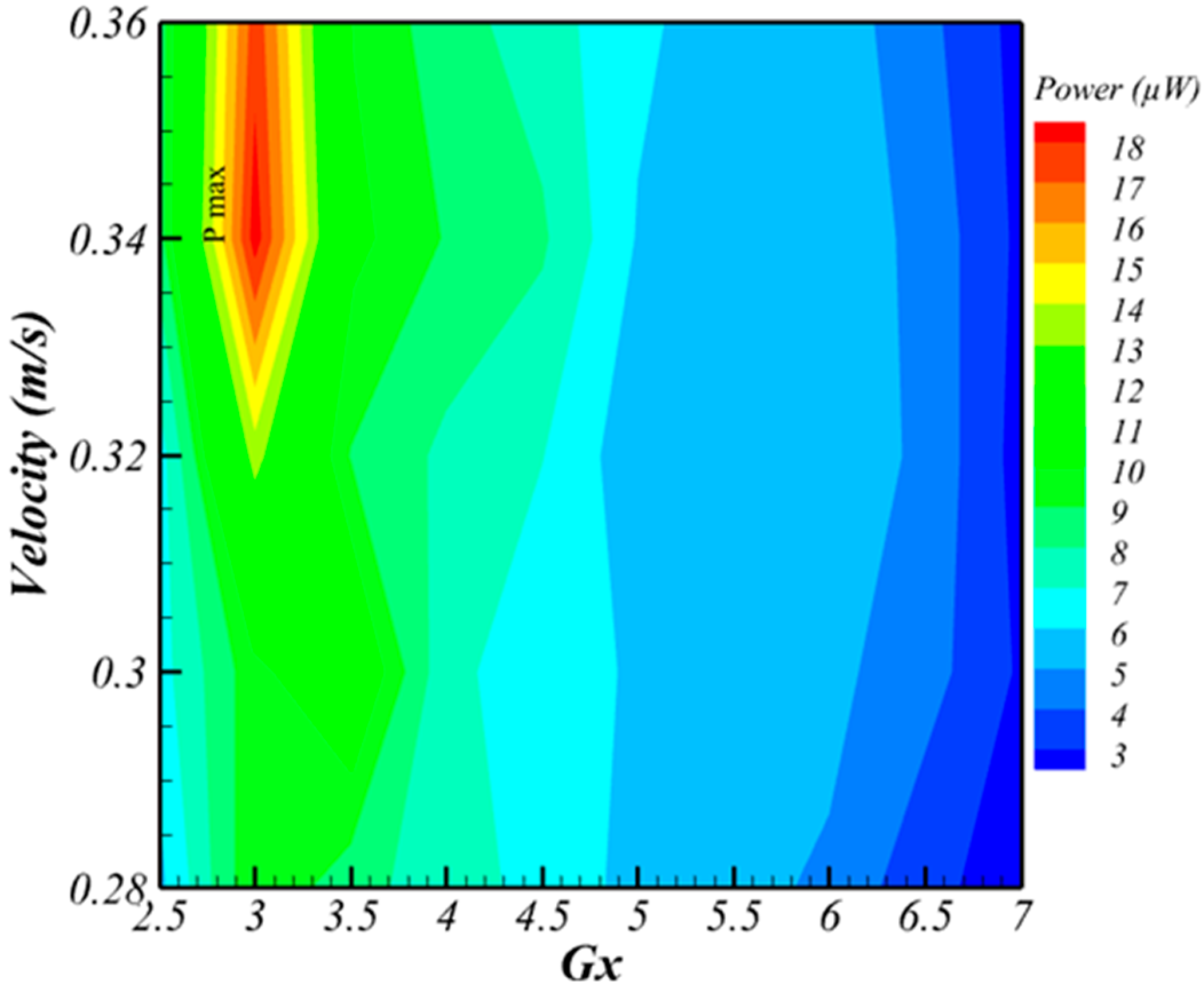
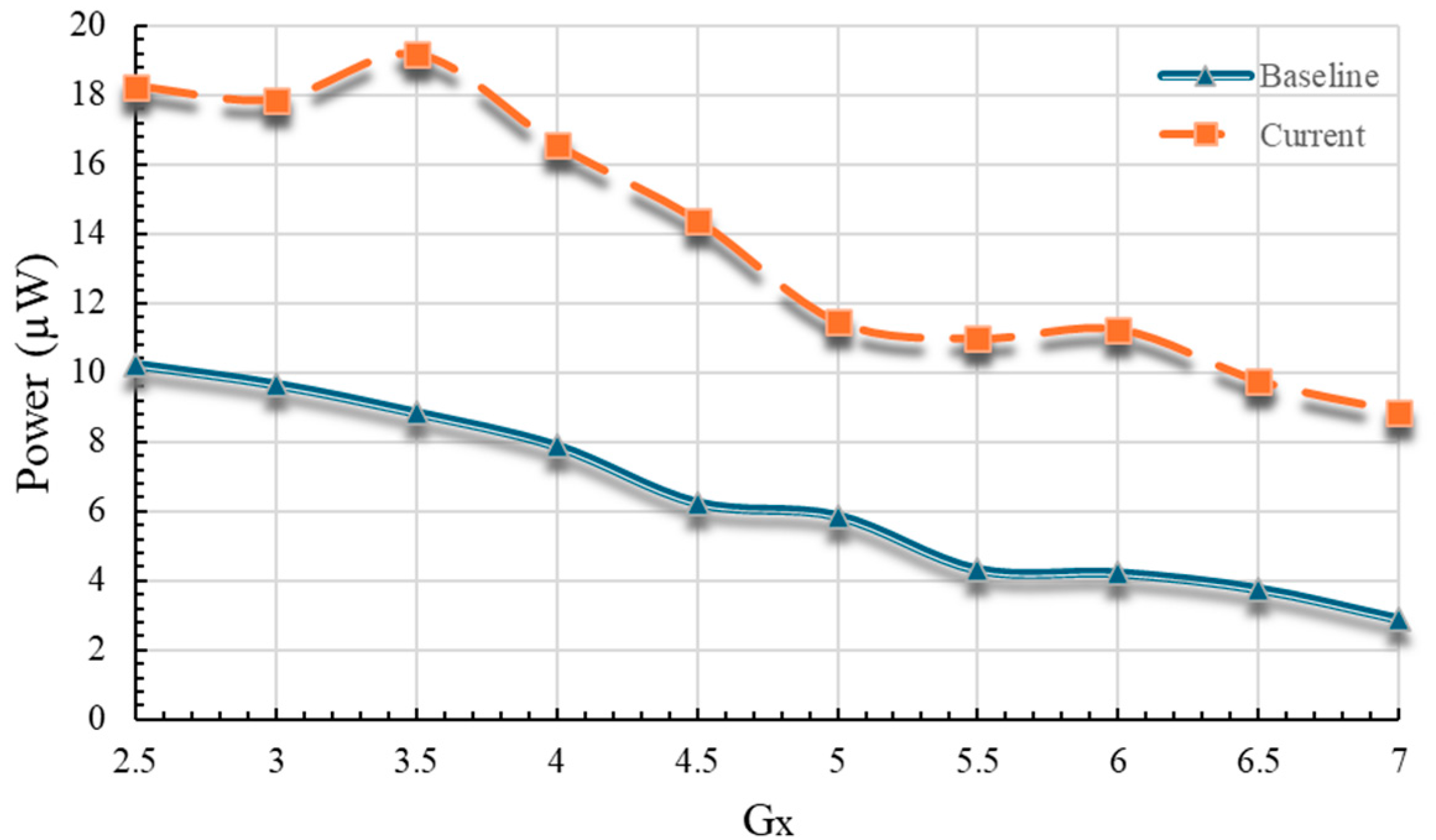
3.1. Effect of Gx
3.2. Effect of Changes in Sx
4. Conclusions
Author Contributions
Funding
Institutional Review Board Statement
Informed Consent Statement
Data Availability Statement
Acknowledgments
Conflicts of Interest
References
- Sezer, N.; Koç, M. A Comprehensive Review on the State-of-the-Art of Piezoelectric Energy Harvesting. Nano Energy 2021, 80, 105567. [Google Scholar] [CrossRef]
- Sanislav, T.; Mois, G.D.; Zeadally, S.; Folea, S.C. Energy Harvesting Techniques for Internet of Things (IoT). IEEE Access 2021, 9, 39530–39549. [Google Scholar] [CrossRef]
- Zhao, M. A Review of Recent Studies on the Control of Vortex-Induced Vibration of Circular Cylinders. Ocean Eng. 2023, 285, 115389. [Google Scholar] [CrossRef]
- Ma, X.; Zhou, S. A Review of Flow-Induced Vibration Energy Harvesters. Energy Convers. Manag. 2022, 254, 115223. [Google Scholar] [CrossRef]
- Rabiee, A.H. Galloping and VIV Control of Square-Section Cylinder Utilizing Direct Opposing Smart Control Force. J. Theor. Appl. Vib. Acoust. 2019, 5, 69–84. [Google Scholar] [CrossRef]
- Mannini, C.; Marra, A.M.; Bartoli, G. VIV–Galloping Instability of Rectangular Cylinders: Review and New Experiments. J. Wind Eng. Ind. Aerodyn. 2014, 132, 109–124. [Google Scholar] [CrossRef]
- Wang, J.; Geng, L.; Ding, L.; Zhu, H.; Yurchenko, D. The State-of-the-Art Review on Energy Harvesting from Flow-Induced Vibrations. Appl. Energy 2020, 267, 114902. [Google Scholar] [CrossRef]
- Allen, J.J.; Smits, A.J. Energy Harvesting Eel. J. Fluids Struct. 2001, 15, 629–640. [Google Scholar] [CrossRef]
- Taylor, G.W.; Burns, J.R.; Kammann, S.A.; Powers, W.B.; Welsh, T.R. The Energy Harvesting Eel: A Small Subsurface Ocean/River Power Generator. IEEE J. Ocean. Eng. 2001, 26, 539–547. [Google Scholar] [CrossRef]
- Akaydın, H.D.; Elvin, N.; Andreopoulos, Y. Wake of a Cylinder: A Paradigm for Energy Harvesting with Piezoelectric Materials. Exp. Fluids 2010, 49, 291–304. [Google Scholar] [CrossRef]
- Gao, X.; Shih, W.-H.; Shih, W.Y. Flow Energy Harvesting Using Piezoelectric Cantilevers With Cylindrical Extension. IEEE Trans. Ind. Electron. 2013, 60, 1116–1118. [Google Scholar] [CrossRef]
- Song, R.; Shan, X.; Lv, F.; Xie, T. A Study of Vortex-Induced Energy Harvesting from Water Using PZT Piezoelectric Cantilever with Cylindrical Extension. Ceram. Int. 2015, 41, S768–S773. [Google Scholar] [CrossRef]
- Wang, J.; Wen, S.; Zhao, X.; Zhang, M.; Ran, J. Piezoelectric Wind Energy Harvesting from Self-Excited Vibration of Square Cylinder. J. Sens. 2016, 2016, 1–12. [Google Scholar] [CrossRef]
- Binyet, E.M.; Chang, J.-Y.; Huang, C.-Y. Flexible Plate in the Wake of a Square Cylinder for Piezoelectric Energy Harvesting—Parametric Study Using Fluid–Structure Interaction Modeling. Energies 2020, 13, 2645. [Google Scholar] [CrossRef]
- Shen, Y.; Wang, J. Energy Harvesting by Applying VIV with a Circular Cylinder and Galloping with a Triangle Cylinder in a Low-Speed Water Flume. In Proceedings of the 32nd International Ocean and Polar Engineering Conference, Shanghai, China, 5 June 2022; p. ISOPE-I-22-079. [Google Scholar]
- Wang, J.; Zhang, C.; Gu, S.; Yang, K.; Li, H.; Lai, Y.; Yurchenko, D. Enhancement of Low-Speed Piezoelectric Wind Energy Harvesting by Bluff Body Shapes: Spindle-like and Butterfly-like Cross-Sections. Aerosp. Sci. Technol. 2020, 103, 105898. [Google Scholar] [CrossRef]
- Chen, K.; Gao, F.; Liu, Z.; Liao, W.-H. A Nonlinear M-Shaped Tri-Directional Piezoelectric Energy Harvester. Smart Mater. Struct. 2021, 30, 045017. [Google Scholar] [CrossRef]
- Li, H.; Liu, D.; Wang, J.; Shang, X.; Hajj, M.R. Broadband Bimorph Piezoelectric Energy Harvesting by Exploiting Bending-Torsion of L-Shaped Structure. Energy Convers. Manag. 2020, 206, 112503. [Google Scholar] [CrossRef]
- Cao, Y.; Cao, D.; He, G.; Ge, X.; Hao, Y. Vibration Analysis and Distributed Piezoelectric Energy Harvester Design for the L-Shaped Beam. Eur. J. Mech.–A Solids 2021, 87, 104214. [Google Scholar] [CrossRef]
- Xie, Z.; Liu, L.; Huang, W.; Shu, R.; Ge, S.; Xin, Y.; Chen, Z.; Lin, W. A Multimodal E-Shaped Piezoelectric Energy Harvester with a Built-in Bistability and Internal Resonance. Energy Convers. Manag. 2023, 278, 116717. [Google Scholar] [CrossRef]
- Yu, H.; Zhang, X.; Shan, X.; Hu, L.; Zhang, X.; Hou, C.; Xie, T. A Novel Bird-Shape Broadband Piezoelectric Energy Harvester for Low Frequency Vibrations. Micromachines 2023, 14, 421. [Google Scholar] [CrossRef]
- Song, T.; Ding, L.; Yang, L.; Ran, J.; Zhang, L. Comparison of Machine Learning Models for Performance Evaluation of Wind-Induced Vibration Piezoelectric Energy Harvester with Fin-Shaped Attachments. Ocean Eng. 2023, 280, 114630. [Google Scholar] [CrossRef]
- Latif, U.; Ali, E.; Uddin, E.; Ali, Z.; Sajid, M.; Shah, S.R.; Younis, M.Y. Experimental Investigation of Energy Harvesting Eel in the Wake of Bluff Body under Ocean Waves. Proc. Inst. Mech. Eng. Part M J. Eng. Marit. Environ. 2021, 235, 81–92. [Google Scholar] [CrossRef]
- Latif, U.; Younis, M.Y.; Idrees, S.; Uddin, E.; Abdelkefi, A.; Munir, A.; Zhao, M. Synergistic Analysis of Wake Effect of Two Cylinders on Energy Harvesting Characteristics of Piezoelectric Flag. Renew. Sustain. Energy Rev. 2023, 173, 113114. [Google Scholar] [CrossRef]
- Mujtaba, A.; Latif, U.; Uddin, E.; Younis, M.Y.; Sajid, M.; Ali, Z.; Abdelkefi, A. Hydrodynamic Energy Harvesting Analysis of Two Piezoelectric Tandem Flags under Influence of Upstream Body’s Wakes. Appl. Energy 2021, 282, 116173. [Google Scholar] [CrossRef]
- Ahmed, A.; Kashif, M.; Rehman, U.U. Energy Harvesting in The Wake of Two Tandem Arranged Cylinders with Downstream Vibrating Cylinder. In Proceedings of the 13th Asian Computational Fluid Dynamics Conference (ACFD 2022), Jeju, Republic of Korea, 16–19 October 2022; pp. 306–307. [Google Scholar]
- Mazharmanesh, S.; Young, J.; Tian, F.-B.; Ravi, S.; Lai, J.C.S. Coupling Performance of Two Tandem and Side-by-Side Inverted Piezoelectric Flags in an Oscillating Flow. J. Fluids Struct. 2023, 119, 103874. [Google Scholar] [CrossRef]
- Shah, M.M.; Mahmood, R.; Latif, U.; Uddin, E.; Munir, A.; Zhao, M.; Riaz, H.H. Experimental Investigation of the Wake of Tandem Cylinders Using Pivoted Flapping Mechanism for Piezoelectric Flag. Ocean Eng. 2024, 310, 118587. [Google Scholar] [CrossRef]


| Variable Gx in terms of D | Variable flow speed “U” in m/s | Total Cases |
| 2.5, 3, 3.5, 4, 4.5, 5, 5.5, 6, 6.5, and 7 | 0.28, 0.30, 0.32, 0.34 and 0.36 | =50 |
| Variable Sx in terms of D | Variable flow speed “U” in m/s | Total Cases |
| 2.5, 3, 3.5, 4, 4.5, 5, 5.5, 6, 6.5, and 7 | 0.28, 0.30, 0.32, 0.34 and 0.36 | =50 |
| Total overall cases | =100 | |
Disclaimer/Publisher’s Note: The statements, opinions and data contained in all publications are solely those of the individual author(s) and contributor(s) and not of MDPI and/or the editor(s). MDPI and/or the editor(s) disclaim responsibility for any injury to people or property resulting from any ideas, methods, instructions or products referred to in the content. |
© 2024 by the authors. Licensee MDPI, Basel, Switzerland. This article is an open access article distributed under the terms and conditions of the Creative Commons Attribution (CC BY) license (https://creativecommons.org/licenses/by/4.0/).
Share and Cite
Shah, M.M.; Ahmed, A.; Latif, U.; Hasan, S.M.; Uddin, E. VIV-Based Energy Harvesting from Tandem Cylinders for Self-Sustained IoT Systems. Eng. Proc. 2024, 75, 40. https://doi.org/10.3390/engproc2024075040
Shah MM, Ahmed A, Latif U, Hasan SM, Uddin E. VIV-Based Energy Harvesting from Tandem Cylinders for Self-Sustained IoT Systems. Engineering Proceedings. 2024; 75(1):40. https://doi.org/10.3390/engproc2024075040
Chicago/Turabian StyleShah, Muhammad Mahad, Arslan Ahmed, Usman Latif, Syed Maaz Hasan, and Emad Uddin. 2024. "VIV-Based Energy Harvesting from Tandem Cylinders for Self-Sustained IoT Systems" Engineering Proceedings 75, no. 1: 40. https://doi.org/10.3390/engproc2024075040
APA StyleShah, M. M., Ahmed, A., Latif, U., Hasan, S. M., & Uddin, E. (2024). VIV-Based Energy Harvesting from Tandem Cylinders for Self-Sustained IoT Systems. Engineering Proceedings, 75(1), 40. https://doi.org/10.3390/engproc2024075040