Abstract
Mechanical gears are essential in power transmission systems across various industrial applications. Their performance is critically influenced by residual stresses from manufacturing processes like induction hardening, case hardening, and shot peening. Surface compressive residual stresses enhance resistance to pitting fatigue, bending fatigue and crack propagation, improving overall hardness. In the present work, a Non-Destructive Thermographic method (Active thermography), based on measurement of the thermal diffusivity parameter, is presented to characterize the surface treatments applied to gears. Surface hardness was measured using a micro-hardness tester, and residual stresses were determined with an X-Ray diffractometer, showing variations due to surface treatments. The variation in the thermal diffusivity parameter, obtained using the Slope Method, was found to be an indicator of the surface treatments’ effectiveness.
1. Introduction
Mechanical gears play an important role in power transmission systems for various industrial applications. Their performance and reliability are strongly influenced by several mechanical parameters, among which surface hardness and residual stresses are particularly significant. These parameters can be achieved through precisely calibrated and controlled manufacturing processes [1]. In particular, surface treatments respond to the need to optimize gear performance in terms of wear and fatigue resistance and pitting and bending fatigue, respectively. Optimized mechanical performance may be achieved through an increase in both surface hardness and core toughness, but also through residual compressive stresses generated by microscopic effects of the surface treatment itself, such as phase changes in the case of heat treatments [2]. Careful control and correct characterization of the surface treatment are of considerable interest, especially for mechanical components, as residual stresses can be beneficial or detrimental depending on the specific application conditions.
Over the years, different methods (destructive, semi-destructive and non-destructive) have been developed to measure residual stress [3]. Destructive and semi-destructive methods measure fundamental quantities (e.g., displacements or strains) and require less specific calibrations in comparison to Non-Destructive methods. Meanwhile, non-destructive techniques are advantageous for specimen preservation and are particularly adopted for production quality control. The most common non-destructive method utilized for residual stress measurement is X-Ray Diffraction (XRD). It is widely adopted since it guarantees high repeatability during the analysis, and the working principles are well consolidated for residual stress computation. In the specific case of XRD application for production quality control, several articles are proposed in the literature. For example, the effects of shot peening and the entire production chain on the residual stress field of a gear were analyzed in [1]. Furthermore [4,5,6], the XRD technique was employed to measure residual stresses induced by induction hardening applied to gears, aiming to investigate the impact of hardening parameters. However, as detailed in [4,5,6], it is evident how the XRD technique becomes destructive when applied to complex geometry such as gears, since it requires cutting the tooth. Based on these considerations, non-destructive residual stress measurement methods represent a challenging field of research, both for academic studies and industrial applications, but further improvements are required in the case of complex geometry components.
An ever-expanding technique in the field of Non-Destructive measurement is Infrared Thermography (IRT). IRT is a Non-Destructive Testing (NDT) methodology that detects thermal energy emitted by objects within the infrared band of the electromagnetic spectrum. It can be classified as Active (AT) or Passive Thermography (PT), depending on the presence or absence of an external excitation source. AT, also called “stimulated thermography”, has mainly been used for the identification of hidden defects, and many papers describe methods to improve the visibility of them [7,8,9]. Thermographic techniques have also been developed to characterize the mechanical and thermal properties of components. The characterization of thermal diffusivity and conductivity properties is critical for process and material selection in industrial manufacturing. In the case of material characterization, AT was successfully applied to characterize Thermal Barrier Coatings (TBCs) for industrial applications [10,11] and Aerogel materials [12], according to the ISO 18555 and ISO 18755 Standards [13,14]. AT was also used as an efficient alternative approach to evaluate possible microstructural alterations due to fatigue damage conditions by using thermal diffusivity variation as a damage parameter. This approach was proposed in [15,16] for classical samples and for mechanical components.
In this work, the potentialities of AT were exploited to characterize different surface treatments. In particular, the proposed method was developed specifically for mechanical components, such as gears. The thermal diffusivity parameter, obtained using the Slope Method [17], was utilized as a thermal index of the effectiveness of the surface treatment, allowing us to determine the correlation with the corresponding mechanical parameters such as hardness and residual stresses.
2. Material and Methods
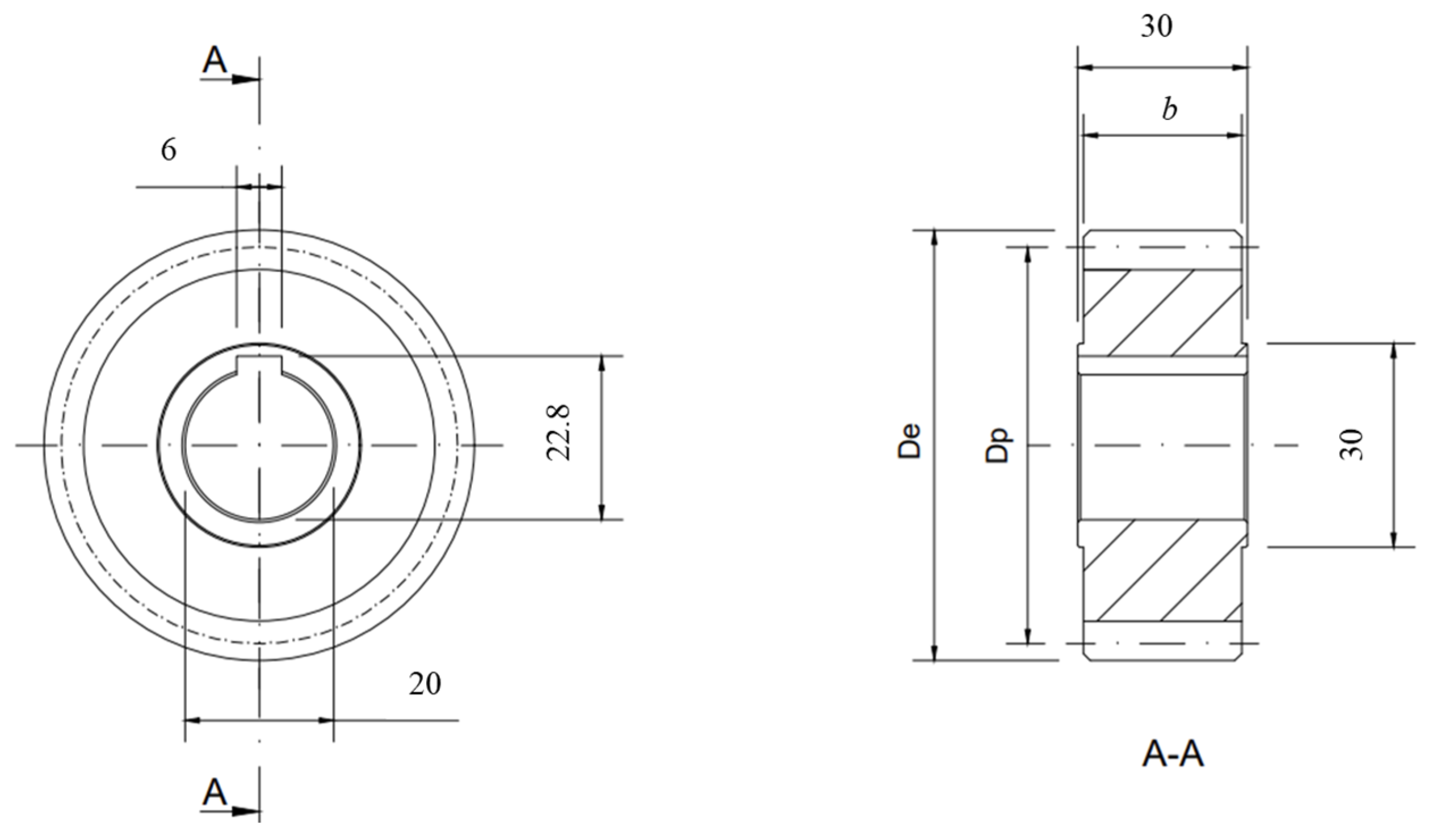
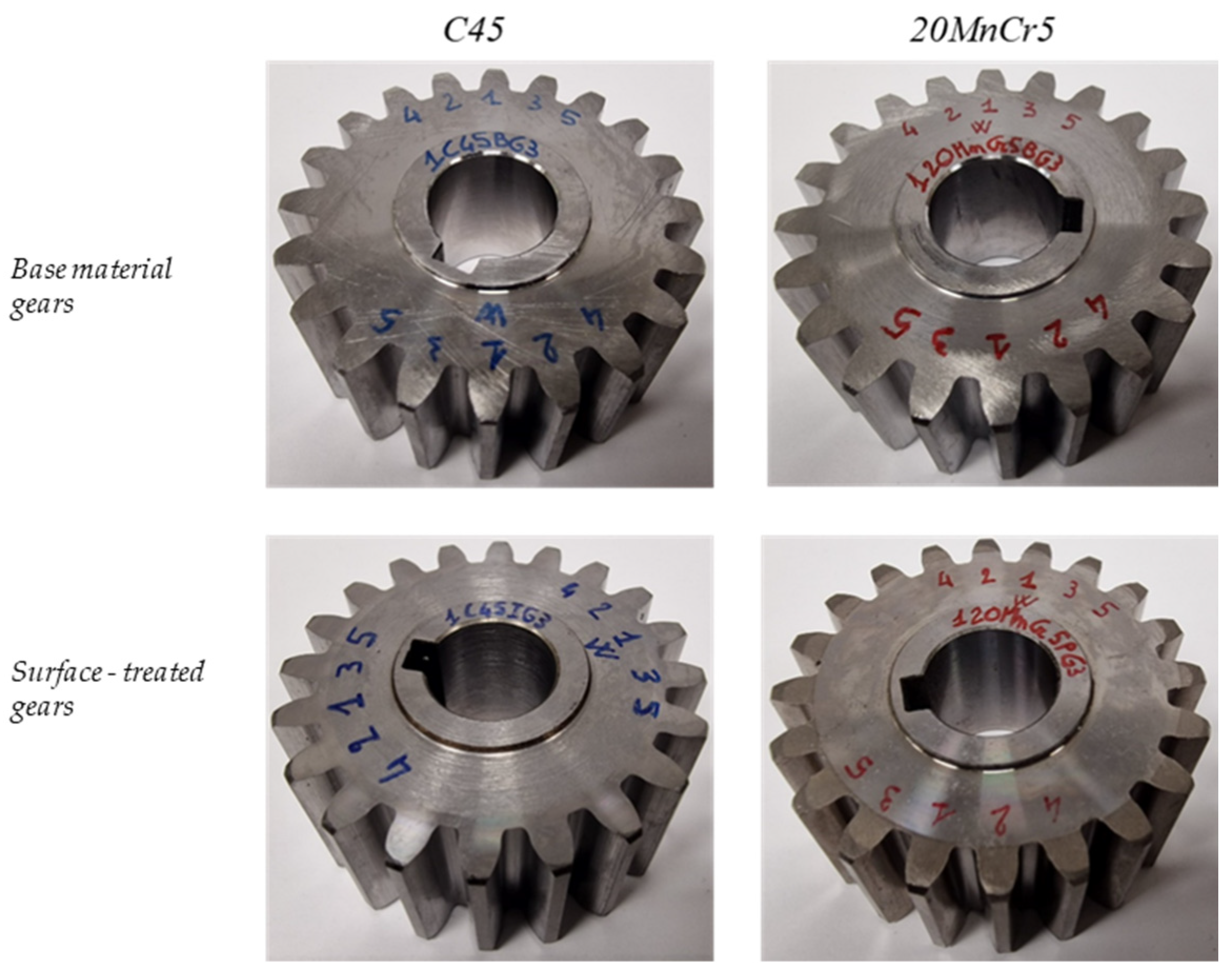
The mechanical components analyzed in this work are gears, made of C45 and 20MnCr5 steel, with and without (base material) surface treatments. In particular, for C45 steel, induction hardening was performed, and for 20MnCr5 steel, case hardening (carburizing) with subsequent shot peening was carried out. Figure 1 and Figure 2 show, respectively, a technical drawing and pictures of gears, whose geometrical parameters are reported in Table 1.
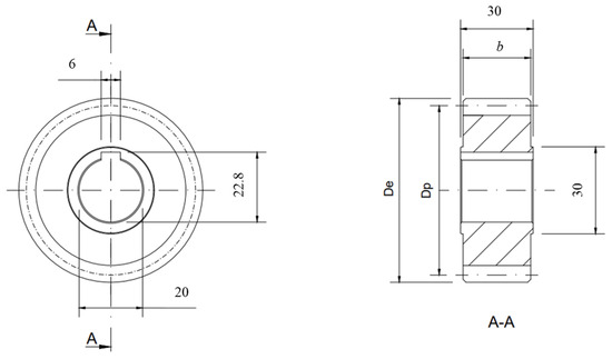
Figure 1.
Technical drawing of analyzed gears: lateral view—left side; section view (A-A)—right side.
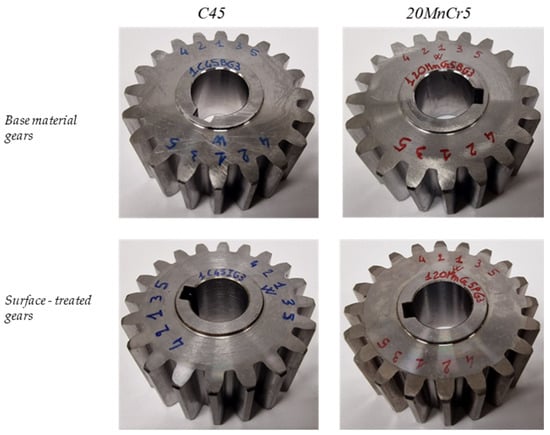
Figure 2.
Tested gears (C45 (left) and 20MnCr5 (right) steel gears): base material—upper images; surface treated—lower images.

Table 1.
Gears’ geometry.
The experimental equipment was composed of an IR thermal camera, a laser excitation source and a PC control unit. The IR thermal camera was an FLIR A6751sc with sensitivity lower than 20 mK and a 3–5 μm spectral range, with a maximum frame rate acquisition of 785.67 Hz. The laser excitation source had a gaussian heating profile with a beam diameter of about 6–8 mm and a maximum power of 50 W. A special device, an F-Theta lens, was used to reduce the beam diameter over the tip of the tooth. The environmental temperature and the humidity were controlled for each test using a thermometer. Figure 3 depicts the experimental setup used during the tests. The thermal responses were elaborated on by using Flir Research IR and IRTA2 software. In this work, the experimental setup was carried out in ‘reflection mode’, positioning the camera at a 455 mm distance from the gears, and the temperature range of measurement was tuned between 0 and 90 °C.
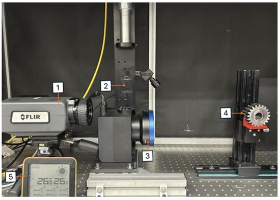
Figure 3.
Experimental setup: (1) The IR thermal camera, (2) laser, (3) F-Theta lens, (4) gear, and (5) thermometer.
The Lock-in AT technique involves the use of an external laser source. In particular, periodic heating, with a square wave of duty cycle equal to 50%, was generated over the tip of the tooth. The surface treatments characterization proposed in this work is based on the identification of microstructural alterations due to these treatments. To this end, the thermal diffusivity parameter was chosen as the thermal index to identify some possible variations in classical mechanical parameters such as hardness and residual stress. The Slope Method [15] was utilized for thermal diffusivity computation, adopting the slope of the phase profile as AT result. The thermal diffusivity parameter was estimated at the tip of the tooth, along its face width, being the only flat area useful for thermographic technique application (see Figure 4a). Figure 4b shows an example of the phase map (the first harmonic of the thermal signal). The phase profile, extracted from a line located over the tip of the tooth (see green line in Figure 4b), was processed by a dedicated MATLAB routine to estimate the thermal diffusivity parameter.
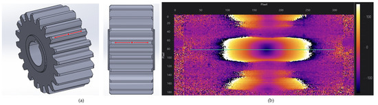
Figure 4.
(a) Investigated zone. (b) Phase map and data extraction line (green line).
Dedicated first- (Taguchi designs) and second-order (response surface methodology) Designs of Experiment (DOEs) were run to obtain the optimal laser parameters (step duration, power and number of cycles). The goal was to obtain the thermal diffusivity values of the base materials (C45 and 20MnCr5 steels) that best matched that measured using classical Hot-Disk apparatus. The cylindrical specimens used in the Hot-Disk measurements were cut from the bar utilized for gear manufacturing and then underwent the same heat treatments in terms of induction hardening (C45 steel) and carburizing surface treatment (20MnCr5 steel). The optimal laser parameters were as follows: step duration of 0.5 s, percentage of power equal to 30 and total number of cycles of 200. A frame rate of 200 Hz was chosen to acquire at least 100 images per second. Once the optimal laser parameters were identified, three thermographic tests were carried out for both the base material gears and treated gears. At the end, the mean value of the thermal diffusivity parameter was considered for the surface treatment characterization. The effectiveness of surface treatments was also verified by hardness and residual stresses measurements. Hardness measurements were carried out using a Vickers indenter (1 kgf with an indentation time of 10 s), and the analysis was performed at five different points on the two faces of each tooth (front and back) and at three different points on the tips. Residual stresses were measured using an X-Ray diffractometer approximately at the pitch diameter, both at the surface along the x- and y-axes, and at depths up to −30 μm along the x-axis.
3. Results and Discussion
All of the results for the induction hardening surface treatment (C45 steel gears) and case hardening with subsequent shot peening (20MnCr5 steel gears) are reported in this section.
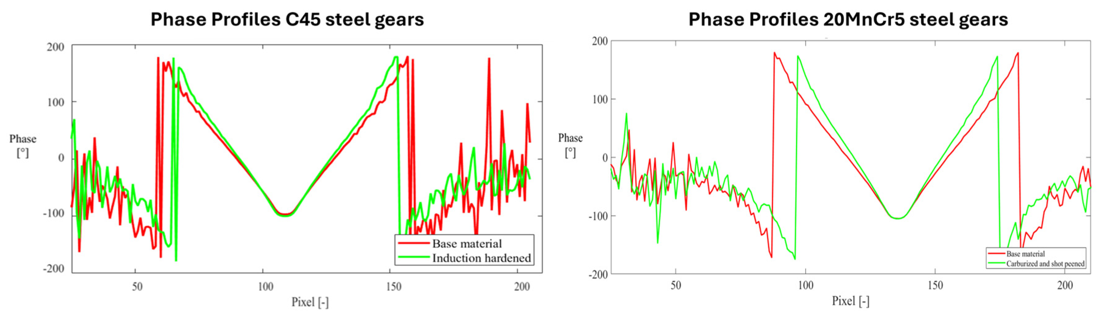
The phase profiles are reported in Figure 5 for C45 steel gears on the left and 20MnCr5 steel gears on the right. The central part of the phase profiles refers to the laser excitation area, while the heat propagation area can be seen on the outside part. Focusing on the heat propagation area, it can be seen that treated gears (green profiles) show a different thermal behavior compared to base material gears (red profiles). This behavior may also be demonstrated by the different thermal slopes. On the basis of this consideration, the Slope Method (see Section 2) was utilized to estimate the thermal diffusivity index for both base and treated gears.

Figure 5.
Phase profiles for C45 (left) and 20MnCr5 (right) steel gears. The red color represents the base material, and the green color represents the treated material.
The results obtained in terms of mechanical and thermal parameter values are shown in Table 2. The thermal diffusivity values correspond to an average value obtained from the three thermographic replications, shown in the table with the corresponding change. Thanks to the homogeneity of the surface treatment, it was possible to consider an average value for the hardnesses measurements. For what concerns the residual stress effects, a mean value of the measurements was utilised as a reference value for each surface treatment. So, Table 2 compares the variation in both the mechanical and thermal parameters of the gears (base material and treated). From the analysis of Table 2, an appreciable thermal diffusivity decrement was obtained for both the investigated surface treatments (induction hardening—C45, and carburizing with subsequent shot peening—20MnCr5) when compared to gears made of the base material. As concerns the mechanical parameters, an increment in both hardness and compressive residual stress was found in gears with the surface treatments.
Table 2.
Mechanical and thermal parameters.
On the basis of the obtained results, it can be pointed out that the microstructural alterations caused by the surface treatments are responsible for a thermal alteration in the phase profiles (see Figure 5). Therefore, quantitative surface treatment characterization can be realized by using the thermal diffusivity as the thermal index, as shown in the Lock-in results.
4. Conclusions
The results obtained in the present work allow us to draw the following conclusions.
The AT method proposed in this work confirms the advantage of the contact-less Thermography technique applied to a wide range of materials and geometries.
The Lock-in technique enables the Non-Destructive detection of various surface treatments, even in complex geometries such as gears. Surface treatment identification can be performed qualitatively through a direct analysis of thermographic signals (phase profiles), or quantitatively by estimating the values of the thermal diffusivity parameter by using the Slope Method [15].
The thermal diffusivity parameter can be adopted as a reliable thermal indicator for complete surface treatment characterization, related classical mechanical parameters such as hardness or residual stress.
A future development will be to find a quantitative correlation between the thermal diffusivity values and the mechanical properties of a gear.
5. Patents
Curà. F., Sesana. R., Corsaro. L., Santoro. L., Metodo di rilevazione delle tensioni residue su materiali e componenti mediante tecniche di termografia attiva. Patent application for industrial invention n. 102023000003597, 2023.
Author Contributions
Conceptualization, L.C. and F.M.C.; methodology, L.C.; software, L.C.; validation, L.C. and L.T.; formal analysis, L.C. and L.T.; investigation, L.C.; resources, L.C.; data curation, L.T.; writing—original draft preparation, L.T.; writing—review and editing, L.C.; visualization, L.C. and F.M.C.; supervision, F.M.C.; project administration, L.C. and F.M.C.; funding acquisition, F.M.C. and L.C. All authors have read and agreed to the published version of the manuscript.
Funding
This research was funded by Fondazione Compagnia San Paolo. Proof of Concept project: “Sviluppo e set up di una metodologia basata sulla termografia attiva per la misura delle tensioni residue nei materiali e nei componenti metallici”, 2023–2024.
Data Availability Statement
The data are contained within the article.
Conflicts of Interest
The authors declare no conflicts of interest.
References
- Rego, R.; Löpenhaus, C.; Gomes, J.; Klocke, F. Residual stress interaction on gear manufacturing. J. Mater. Process. Technol. 2018, 252, 249–258. [Google Scholar] [CrossRef]
- Bhadeshia, H. Material Factors. In Handbook of Residual Stress and Deformation of Steel, 1st ed.; Chapter 1; Totten, G., Howes, M., Inoue, T., Eds.; ASM International: Materials Park, OH, USA, 2002; pp. 3–10. [Google Scholar]
- Rossini, N.S.; Dassisti, M.; Benyounis, K.Y.; Olabi, A.G. Methods of measuring residual stresses in components. Mater. Des. 2012, 35, 572–588. [Google Scholar] [CrossRef]
- Misaka, Y.; Kiyosawa, Y.; Kawasaki, K.; Yamazaki, T.; Silverthorne, W.O. Gear contour hardening by micropulse induction heating system. In Proceedings of the 1997 SAE International Congress & Exposition, Detroit, MI, USA, 24–27 February 1997. [Google Scholar] [CrossRef]
- Rodman, D.; Krause, C.; Nürnberger, F.; Bach, F.W.; Gerdes, L.; Breidenstein, B. Investigation of the surface residual stresses in spray cooled induction hardened gearwheels. Int. J. Mater. Res. 2012, 103, 73–79. [Google Scholar] [CrossRef]
- Savaria, V.; Monajati, H.; Bridier, F.; Bocher, P. Measurement and correction of residual stress gradients in aeronautical gears after various induction surface hardening treatments. J. Mater. Process. Technol. 2015, 220, 113–123. [Google Scholar] [CrossRef]
- Ben Larbi, W.; Klein, M.; Bendada, A.; Maldague, X. Experimental Comparison of Lock-in and Pulsed Thermography for the Nondestructive Evaluation of Aerospace Materials. In Proceedings of the 6th International Workshop Advances in Signal Processing for Non Destructive Evaluation of Materials, London, ON, Canada, 25–27 August 2009. [Google Scholar]
- Liu, J.; Yang, W.; Dai, J. Research on thermal wave processing of lock-in thermography based on analyzing image sequences for NDT. Infrared Phys. Technol. 2010, 53, 348–357. [Google Scholar] [CrossRef]
- Ibarra-Castanedo, C.; Piau, J.M.; Guilbert, S.; Avdelidis, N.P.; Genest, M.; Bendada, A.; Maldague, X. Comparative Study of Active Thermography Techniques for the Nondestructive Evaluation of Honeycomb Structures. Res. Nondestruct. Eval. 2009, 20, 1–31. [Google Scholar] [CrossRef]
- Curà, F.; Sesana, R.; Corsaro, L.; Mantoan, R. Active thermography technique for barrier coatings characterization. IOP Conf. Ser. Mater. Sci. Eng. 2022, 1214, 012034. [Google Scholar] [CrossRef]
- Curà, F.; Sesana, R.; Corsaro, L.; Mantoan, R. Characterization of Thermal Barrier Coatings Using an Active Thermography Approach. Ceramics 2022, 5, 848–861. [Google Scholar] [CrossRef]
- Curà, F.; Sesana, R.; Dugand, M.; Corsaro, L. Active thermography characterization of aerogel materials for vehicle electrification. IOP Conf. Ser. Mater. Sci. Eng. 2023, 1275, 012014. [Google Scholar] [CrossRef]
- ISO 18555:2016; Metallic and Other Inorganic Coatings—Determination of Thermal Conductivity of Thermal Barrier Coatings. International Organization for Standardization: Geneva, Switzerland, 2016.
- ISO/FDIS 18755:2004; Fine Ceramics [Advanced Ceramics, Advanced Technical Ceramics]—Determination of Thermal Diffusivity of Monolithic Ceramics by Laser Flash Method. International Organization for Standardization: Geneva, Switzerland, 2004.
- Curà, F.; Sesana, R.; Corsaro, L.; Santoro, L. La termografia attiva applicata allo studio della fatica nei materiali metallici: Un caso studio. In Proceedings of the AIPnD 2022—Conferenza Nazionale sulle Prove Non Distruttive, Monitoraggio e Diagnostica, Verona, Italy, 19–20 October 2022. [Google Scholar]
- Curà, F.; Sesana, R.; Corsaro, L. Active thermography technique for fatigue damage characterization in gears. In Experimental Mechanics in Engineering and Biomechanics, Proceedings of the ICEM20 20th International Conference on Experimental Mechanics, Porto, Portugal, 2–7 July 2023; Universidade do Porto: Porto, Portugal, 2023. [Google Scholar]
- Mendioroz, A.; Fuente-Dacal, R.; Apiñaniz, E.; Salazar, A. Thermal diffusivity measurements of thin plates and filaments using lock-in thermography. Rev. Sci. Instrum. 2009, 80, 074904. [Google Scholar] [CrossRef] [PubMed]


Disclaimer/Publisher’s Note: The statements, opinions and data contained in all publications are solely those of the individual author(s) and contributor(s) and not of MDPI and/or the editor(s). MDPI and/or the editor(s) disclaim responsibility for any injury to people or property resulting from any ideas, methods, instructions or products referred to in the content. |
© 2025 by the authors. Licensee MDPI, Basel, Switzerland. This article is an open access article distributed under the terms and conditions of the Creative Commons Attribution (CC BY) license (https://creativecommons.org/licenses/by/4.0/).