Abstract
Hybrid Rocket Engines (HREs) combine the advantages of solid and liquid propellants, offering thrust control, simplicity, safety, and cost efficiency. Part of the research on this rocket architecture focuses on optimising combustion chamber design to enhance performance, a process traditionally reliant on time-consuming experimental adjustments to chamber lengths. In this study, two configurations of HREs were designed and tested. The tests aimed to study the impact of post-chamber lengths on rocket engine performance by experimental firings on a laid-back test engine. This study focused on designing, manufacturing, and testing a laid-back hybrid engine with two chamber configurations. The engine features a small combustion chamber, an L-shaped mount, a spark ignition, and nitrogen purging. Data acquisition includes thermocouples, pressure transducers, and a load cell for thrust measurement. Our experimental findings provide insights into thrust, temperature gradients, pressure, and plume characteristics. A non-linear regression model derived from the experimental data established an empirical relationship between performance and chamber lengths, offering a foundation for further combustion flow studies. The post-chamber length positively impacted the engine thrust performance by 2.7%. Conversely, the pre-chamber length negatively impacted the performance by 1.3%. Further data collection could assist in refining the empirical relation and identifying key threshold values.
1. Introduction
A typical Hybrid Rocket Engine consists of a liquid propellant tank, a feed system, a solid propellant combustion chamber, and a nozzle. During operation, the liquid propellant flows into the chamber, vaporises, and reacts with the solid propellant in a boundary layer diffusion flame. Combustion occurs rapidly, and exhaust gases are expelled through the nozzle at the end of the combustion chamber. Most hybrid systems use a liquid oxidiser, such as Nitrous Oxide (N2O) or Isopropyl Alcohol (IPA), and a solid fuel, such as High-Density Polyethylene (HDPE) or paraffin wax, sometimes enhanced with energy additives (e.g., aluminium or metal hydrides).
Hybrid Rocket Engines combine the advantages of solid and liquid propellants, offering simplicity and throttling capabilities, and they can be used for suborbital missions, sounding rockets, launch vehicles, target drones, and space tourism.
HREs are valued for their safety, cost-efficiency, and re-usability but face challenges, such as low solid fuel regression rates and limited combustion efficiency, depending on the propellant configuration. Optimising combustion chamber design—particularly pre- and post-combustion chamber lengths—is essential for enhancing performance.
The optimisation of HRE combustion chambers has been extensively studied. Dequick et al. (2021) used computational fluid simulations to analyse the effects of pre- and post-combustion chamber lengths on a 1 kN (kilo-Newton) paraffin-fuelled hybrid motor. Extending the post-combustion chamber significantly improved thrust and chamber pressure, while longer pre-combustion chambers showed diminishing returns [1].
Gontijo et al. (2023) examined pre-combustion chamber stability, developing a vapourisation model to determine optimal length-to-diameter ratios of 0.26–0.66. This balance prevents combustion instabilities while avoiding unnecessary weight and heat losses [2].
Dabanović et al. (2024) highlighted the linear improvement in combustion efficiency with longer post-combustion chambers but noted the trade-off with added structural mass. Their study emphasised turbulence’s role in optimising chamber length [3].
Wu et al. (2024) reviewed advancements in hybrid propulsion, including fuel grain design, 3D printing, and numerical modelling. These innovations enhanced performance and scalability for modern hybrid engines [4].
These studies, along with the research undertaken by [5,6,7], underline the importance of optimising combustion chamber geometry to improve thrust, stability, and efficiency. Future research could focus on integrating new materials and designs to further advance hybrid rocket technology.
2. Methods
This section presents the methodology and the rationale for the system design and testing. The hybrid engine combined HDPE as solid fuel and liquid Nitrous Oxide (N2O) as the oxidiser. The system, mounted on an L-shaped stand with a spark ignition system, used gaseous oxygen as pre-charge and nitrogen for purging.
2.1. Engine Design
This section describes the design selection methodology for the combustion chamber, feed line, and control sub-system. The engine design prioritised cost-effective manufacturing with steel piping of 5 mm thickness and HDPE fuel blocks. The chamber featured a 5 mm insulating cork layer for thermal protection, and circular bore geometry was chosen for its simple fabrication and thrust measurement and for its simplicity in developing the empirical relations.
Two different setups of hybrid engines were studied within this research work, and their main performance parameters are described in Table 1:

Table 1.
Engine configurations: 2 setups studied within the research work targeting 2 separate thrust values with the same geometrical configuration.
The E-500 was inspired by a scaled-up version of the E-300, which has similar geometry and setup but different combustion chamber characteristics.
N2O and HDPE were selected for safety, availability, and cost-effectiveness, with an oxidiser-fuel ratio of 7.6. Engine simulations using the ProPep3 and RPA (Rocket Propulsion Analysis) software tools provided engine characteristics under frozen-flow stable conditions, excluding the effects of the vapour phase. An assumption of 100% combustion efficiency was considered during the simulation runs, and the characteristic inputs from Table 2 were employed for the model.
Table 2.
Parametric inputs for RPA analyses to determine final-state stabilised flow characteristics.
The mass flow rate of N2O for E-300 was selected as 0.164 kg s−1, and the mass flow rate for E-500 was 0.242 kg s−1, leading to a similar burn rate of 1.84 mm s−1 for both configurations.
Considering the mono-propellant flow through the feed-line system and the low thrust profile, a showerhead injector design was selected. An axial pathway helped simplify the characterisation of the engine’s performance. A showerhead axial injector design atomised the oxidiser into fine droplets for vapourisation in the combustion chamber. With a discharge coefficient () of 0.8 [8], the optimal injector design for engine E-300 featured 6 holes: 1 central and 5 in a radial arrangement with a PCD of 5 mm. The injector plate for the engine E-500 featured 10 holes: 4 in a Pitch Circle Diameter (PCD) of 2 mm and 6 in a PCD of 4 mm. Each hole has a diameter of 1 mm, adhering to guidelines for effective atomisation [9]. Figure 1 shows the injector model designed for the 2 configurations.

Figure 1.
Injector plate design for E-300 (left) and E-500 (right): With a similar screw and plug-in design to the combustion chamber and the same injection holes, the plates were tested for operational improvement and de-risking the assembly point.
The nozzle design selection was governed by ease of manufacturing and associated complexity. For the supersonic exhaust flow, the nozzle design employed a converging - diverging bell with a conical diverging section, a contraction ratio of 3.7, and a half-cone angle. Thermocouple ports were placed at and aft of the throat. Graphite (Duragraph 150) material was chosen for its moderate thermal stress and oxidation resistance. The design for the nozzle had been iterated and improved through previous projects.
A 15 kV DC (Direct Current) high-voltage arc ignitor lit a 1 m fuse inserted via the nozzle mouth into the pre-combustion chamber. The ignitor, controlled wirelessly via a triggering circuit, generated a spark to initiate combustion.
The feed system consisted of 3 tanks: for industrial-grade nitrous oxide as the oxidiser, for oxygen (used as pre-charge), and for gaseous nitrogen for purging. The system included multiple safety measures, such as flame restrictors and non-return valves (NRVs) to ensure controlled gas flow.
2.2. Testing
The tests for the system were classified at sub-system and overall system levels to assess the functionality of each sub-system and the performance of the designed system in the test environment. The system test plans are discussed in the following section.
- Cold-flow testing: The cold-flow testing evaluated the feed line system and integration ahead of the fire testing. It involved loading the tanks, running the pre-fire sequence, and initiating oxidiser flow into the chamber for a defined duration without ignition, ensuring the proper flow of all three fluids in the test setup.
- Hot-fire testing: The hot-fire testing involved igniting the combustion chamber to initiate and sustain the combustion reaction. The ignitor raised the chamber temperature, and a steady oxidiser flow maintained combustion, with supersonic flow through the nozzle. Data acquisition started early for calibration and records throughout the test.
- Data Analyses: The data through multiple test iterations were collected and analysed in Matlab. A linear regression model was used to establish a correlation between thrust values and chamber length, with other environmental parameters as crucial factors. These results were plotted and discussed in the next section.
The controls for hot-fire testing require a 24 V control box with operational modes as defined in Table 3.
Table 3.
Control box modes defined for hot-fire testing, to ensure proper and safe operations, and implemented using a multi-switch knob for actuating different modes.
The DAQ system deployed for both the E-300 and the E-500 consisted of sensors employed over the engine test stand to measure the performance characteristics. The sensors deployed on the assembly were an S-block load cell for thrust measurement, pressure transducers for internal combustion chamber pressure and feed line pressure measurement, and K-type thermocouples for temperature measurements. The DAQ schematic is shown in Figure 2:
Figure 2.
Data acquisition system schematic for the hybrid engine test operations, including sensors for thrust, pressure, and temperature measurements and their layout across the engine assembly.
The load cell measured the thrust produced during the firing. The S-block load cell used was the Tedea Huntleigh 615, with a load capacity of 100 kg. However, a load cell amplifier needed to be used for reading the output. This aided in effectively reading the signals.
3. Results and Discussion
The physical testing included multiple hot-fire tests conducted in collaboration with Protolaunch UK (Figure 3). The E-300 engine was tested with a 300 mm fuel block, yielding a peak thrust of 286.4 N, which was close to the 300 N target. A yield thrust of 488 N, which was close to the 500 N target, was measured for the E-500 engine tested with a 500 mm fuel block. Dynamic pressure, temperature and thrust data were collected and are shown in Table 4. The peak pressure recorded during the test was about 29.15 bars (for E-300) and 33 bars (for E-500).

Figure 3.
Hot-fire testing (E-300) with 12 s burn time. Stabilised flow with Mach diamonds (right), performed at NTP conditions with Protolaunch test bed.
Table 4.
Performance metrics recorded for the two engine configurations from the sensor measurements and error percentage values.
The measured results from the experimentation, as described in Table 4, corresponded to the estimated values for pressure and thrust, with a slight deviation under 5%, while temperature variations were observed due to time-varying unsteady burn.
The values from the thermocouples were reported at the outer surface of the chamber pipe, and, thus, conversion to internal temperature was performed by calculating thermal conduction across the mild steel pipe thickness. For the fluid temperature () on the longitudinal axis for the internal wall temperature (),
where A is the surface area of the internal wall, 0.06 m3, and h is the convective heat transfer coefficient, defined as
where is the fluid’s thermal conductivity, 0.026 W m−1 K−1, Re is the Reynolds number, Pr is the Prandtl number, is the flow density, 1.97 kg m−3, v is the flow velocity, is the dynamic viscosity, and is the specific heat capacity.
3.1. Comparative Analysis and Correlation
To assess the engines, engine E-300 had to be extrapolated to the output of engine E-500, so as to realise the effects of the different chamber lengths and configurations for both cases. The configurations for the two engines were as follows:
- E-300: 375 mm main-combustion chamber length, 20 mm pre-combustion chamber length, 3 mm post-combustion chamber length;
- E-500: 500 mm main-combustion chamber length, 25 mm pre-combustion chamber length, 50 mm post-combustion chamber length.
3.1.1. Normalisation
Thrust generation in rocket engines is primarily determined by the exhaust velocity () and nozzle exit area (), which govern the momentum transfer of the exhaust gases. Additionally, the lengths of the combustion chambers influence the engine performance. In this study, two configurations were analysed to establish a relationship between the chamber lengths and the engine performance. To enable meaningful comparisons between these configurations, the thrust data from the E-300 engine were normalised relative to the E-500 engine.
Normalising the thrust values eliminated biases caused by the differences in the engine dimensions, allowing for a focused analysis of the effects of the pre- and post-combustion chamber lengths ( and ). The experimental thrust data were scaled to ensure consistency, providing a baseline for the correlation analysis.
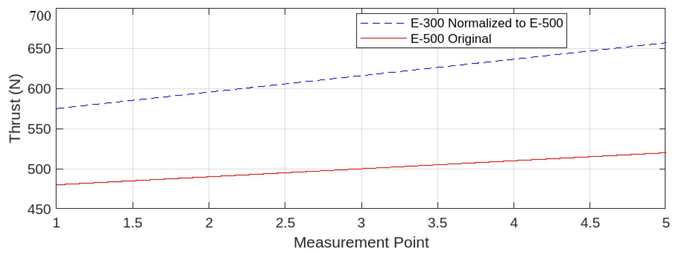
The graph in Figure 4 presents the thrust plot of the E-500 engine alongside the normalised thrust plot of the E-300 engine. For the E-500, a thrust range of 497 N to 503 N was assumed, with 497 N as the measured value and 500 N as the target median. A composite scaling factor of 2.0537 was derived by analysing the relationship between thrust performance and key independent parameters, such as pressure, temperature, and mass flow rate. This factor was applied to normalise the E-300 thrust values against the E-500’s defined thrust range, facilitating a direct comparison of the two configurations.
Figure 4.
Thrust normalisation performed in post-processing, using the thrust measurement results from the hot-fire testing of the E-300 and E-500 engines.
3.1.2. Correlation Analyses and Formulation
While and dominated thrust, secondary contributions arose from the geometry of the combustion chambers. A linear empirical model was introduced to quantify these effects, and the coefficients were derived through a linear regression model.
Using pre- and post-combustion chamber lengths of E-300 and E-500, the model quantified their influence on thrust. The normalised values for E-300 adapted for the E-500 configuration were used to realise the impact of the chamber lengths on the performance effectively. This approach refined performance prediction while maintaining the primary contributions from the exhaust dynamics. Equation (3), derived from linear regression, established the relation of the engine output to the chamber lengths:
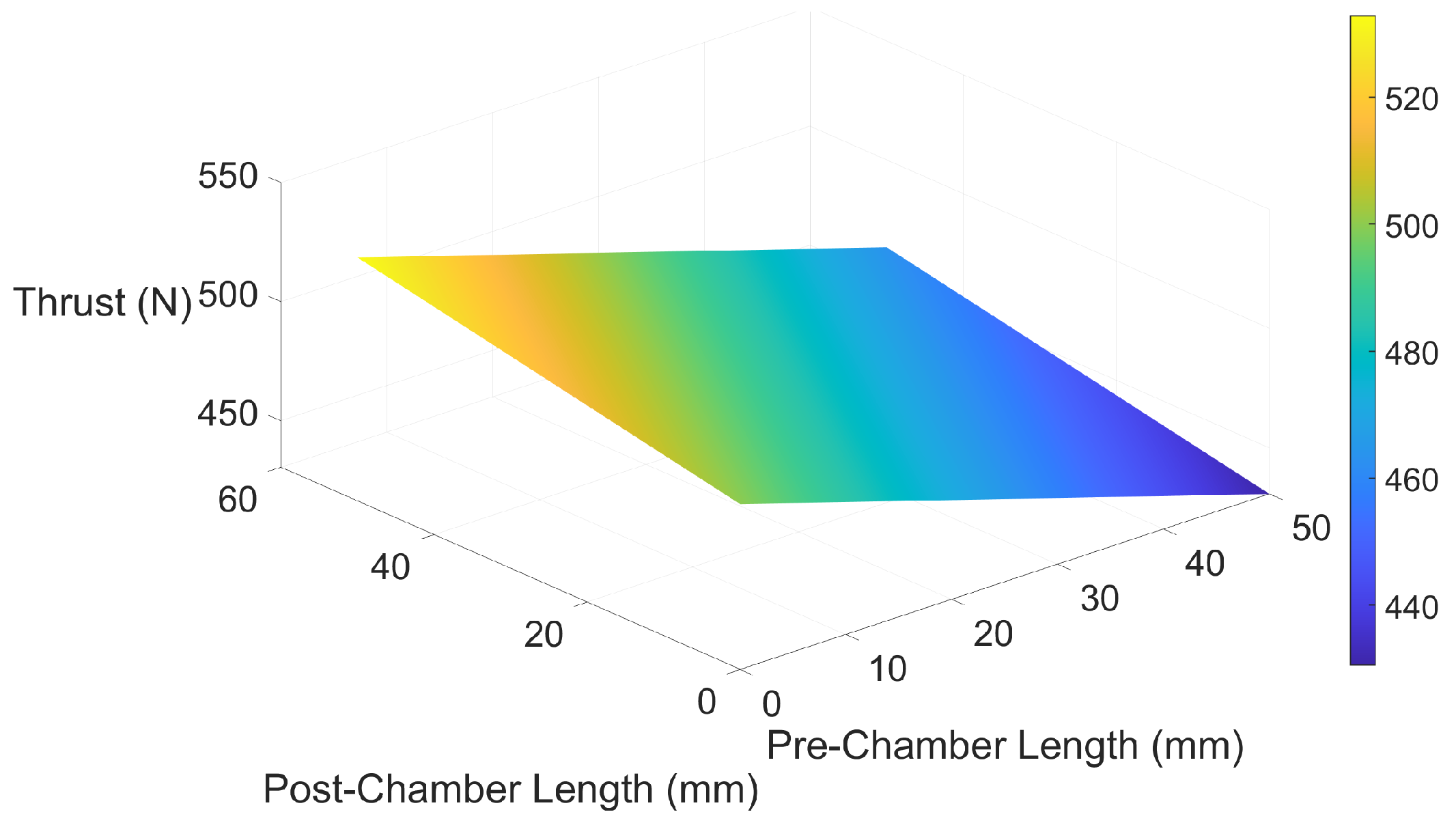
The analyses were visualised using the 3D plots of thrust against the pre-combustion chamber length and the post-combustion chamber length in Figure 5. The plot represents the effective empirical relation for E-500 with varying pre- and post-chamber lengths, illustrating how changes in chamber dimensions impacted thrust. This provided a comprehensive framework for analysing and optimising thrust generation.

Figure 5.
Thrust prediction through empirical correlation, based on the test results collected from hot-fire testing.
Increasing the post-chamber length enhanced combustion efficiency by giving the oxidiser–fuel mixture more reaction area to interact and combust, resulting in higher thrust. Conversely, the pre-chamber length, where only the oxidiser existed at high temperature and pressure without fuel, reduced combustion efficiency. Longer pre-chamber lengths decreased the likelihood of combustion upon ignition, leading to lower thrust values.
The relationship between thrust performance and chamber lengths is non-linear; if it were linear, the ideal post-chamber length would be infinite, and the ideal pre-chamber length would be zero. Instead, threshold values exist for both lengths, beyond which performance declines steeply. Identifying these thresholds, specific to the engine and propellants, requires further testing and a larger dataset for effective correlation.
4. Discussion
The design and testing of the two hybrid engines, E-300 and E-500, provided valuable insights into performance metrics, such as thrust and pressure outputs. Minor deviations (<5%) highlighted the need for refining the injector design and chamber geometry to enhance combustion efficiency. The experimental analysis emphasised the role of chamber lengths in engine performance, with the empirical correlation (Equation (3)) quantifying the impact of the pre- and post-chamber lengths. Longer post-chamber lengths improved combustion efficiency by 2.7%, while extended pre-chamber lengths reduced it by 1.3%, demonstrating a non-linear relationship with efficiency dropping steeply beyond certain thresholds. Further testing is required to precisely define these thresholds and validate the findings.
Testing configurations E-300 and E-500, normalised with a scaling factor of 2.0537, highlighted the dependency of thrust performance on chamber dimensions. Future work should employ advanced combustion and flow dynamics simulations to expand the datasets and enhance accuracy.
4.1. Study Limitations
- Combustion Efficiency: Improvements in injector design and chamber geometry are needed to optimise fuel utilisation.
- Scalability: The findings require validation for engines of different sizes, propellant types, and engine configurations.
- Budget Constraints: The resource limitations restricted system design improvements, particularly for combustion chambers, feed lines, and electronics.
4.2. Applications and Implications
- Optimised chamber geometries could benefit small-scale-to-medium-scale engines for satellite launches and experimental propulsion systems.
- The established empirical correlation offers a predictive tool for thrust and efficiency, guiding injector and chamber design refinements.
5. Conclusions
This study successfully demonstrated the critical performance characteristics of Hybrid Rocket Engines, achieving thrust and pressure deviations of less than 5% from the expected values. The findings highlight the significant influence of chamber lengths on engine efficiency and thrust. Specifically, the increased post-chamber lengths enhanced combustion efficiency by 2.7%, while the longer pre-chamber lengths reduced it by 1.3%. These results underline the non-linear relationship between chamber dimensions and performance, with steep efficiency drops observed beyond certain thresholds.
The empirical correlation established in this study provides a basis for predicting thrust performance based on chamber dimensions. However, further validation is necessary to extend its applicability to engines of varying sizes and propellant types. Our budget constraints limited the system optimisation opportunities, but in-house manufacturing facilitated rapid prototyping and testing, enabling effective validation of engine performance.
Future work should focus on refining injector designs and chamber geometries, employing advanced simulations to expand datasets, and validating scalability to larger engines. These efforts will enhance the applicability of the findings and contribute to the development of efficient and reliable hybrid rocket engines.
Author Contributions
Conceptualisation, T.P.A., N.B. and S.K.; methodology, T.P.A.; software, T.P.A.; validation, T.P.A. and N.B.; formal analysis, T.P.A., N.B. and P.K.; investigation, T.P.A., N.B., P.K., S.K. and E.K.; resources, T.P.A. and N.B.; data curation, T.P.A.; writing—original draft preparation, T.P.A.; writing—review and editing, T.P.A., A.I. and D.d.G.; visualisation, T.P.A.; supervision, A.I., D.d.G. and S.K.; project administration, T.P.A., S.K. and N.B.; funding acquisition, T.P.A., S.K. and N.B. All authors have read and agreed to the published version of the manuscript.
Funding
This research was funded by the Center of Autonomous and Cyberphysical Systems, School of Aerospace, Transport and Manufacturing, Cranfield University.
Institutional Review Board Statement
Not applicable.
Informed Consent Statement
Not applicable.
Data Availability Statement
Further data and information on the project are available on the open-source GitHub webpage for the project team: https://github.com/Triyanpal/HYROE version 1.1 (accessed on 13 March 2025).
Acknowledgments
The authors would like to thank the School of Aerospace, Transport and Manufacturing, Cranfield University and the Centre for Autonomous and Cyberphysical Systems for their financial backing and technical guidance. Huge thanks to Protolaunch UK for providing their test bed and technical assistance to the project. Thanks to Race2Space UK organisers and Westcott Innovation and Venture Park for the opportunity to hot-fire test our engines. Special mention to the CranSEDS student body for providing the team and resources for the project. Huge thanks to Adam Baker for his project supervision and guidance.
Conflicts of Interest
The authors declare no conflicts of interest.
Abbreviations
The following abbreviations are used in this manuscript:
| HREs | Hybrid Rocket Engines | HDPE | High-Density Polyethylene |
| DAQ | Data-Acquisition system | N2O | Nitrous Oxide |
| length-to-diameter ratio | NRVs | Non-Return Valves | |
| PCD | Pitch Circle Diameter | RPA | Rocket Propulsion Analysis |
| Discharge Coefficient | exhaust velocity |
References
- Dequick, B.; Lefebvre, M.; Hendrick, P. Numerical investigation of the geometrical design of a 1 kN paraffin-fueled hybrid rocket motor. Aerosp. Sci. Technol. 2021, 60, 1–10. [Google Scholar] [CrossRef]
- Gontijo, M.S.; Filho, R.B.N. Design of pre-combustion chambers for hybrid propellant rocket motors and related aspects. In Proceedings of the AIAA SciTech 2023 Forum, National Harbor, MD, USA, 23–27 January 2023. [Google Scholar] [CrossRef]
- Dabanović, A.; Martin, J.; May, S.; Wartemann, V. Numerical study on post-combustion chamber impact on hybrid rocket performance. Res. Sq. 2024. [Google Scholar] [CrossRef]
- Wu, J.-S. A review of recent developments in hybrid rocket propulsion and its applications. Aerospace 2024, 11, 739. [Google Scholar] [CrossRef]
- Srivastava, S.; Thakur, A.K. Regression rate and combustion efficiency of composite hybrid rocket grains based on modular fuel units. Aerosp. Syst. 2023, 6, 119–128. [Google Scholar] [CrossRef]
- Heeg, F.; Kilzer, L.; Seitz, R.; Stoll, E. Design and Test of a Student Hybrid Rocket Engine with an External Carbon Fiber Composite Structure. Aerospace 2020, 7, 57. [Google Scholar] [CrossRef]
- Cai, G.; Zhu, H.; Rao, D.; Tian, H. Optimal design of hybrid rocket motor powered vehicle for suborbital flight. Aerosp. Sci. Technol. 2013, 25, 114–124. [Google Scholar] [CrossRef]
- Lee, J.; Bertoldi, A.; Andrianov, A.; Borges, R.; Veras, C.; Battistini, S.; Morita, T.; Hendrick, P. Role of Precombustion Chamber Design in Feed-System Coupled Instabilities of Hybrid Rockets. J. Propuls. Power 2020, 36, 796–805. [Google Scholar] [CrossRef]
- Newland, R.M. The Science and Design of the Hybrid Rocket; Aspirespace Rocket Engineering Society: UK, 2017; ISBN 978-0-244-90291-9. [Google Scholar]

Disclaimer/Publisher’s Note: The statements, opinions and data contained in all publications are solely those of the individual author(s) and contributor(s) and not of MDPI and/or the editor(s). MDPI and/or the editor(s) disclaim responsibility for any injury to people or property resulting from any ideas, methods, instructions or products referred to in the content. |
© 2025 by the authors. Licensee MDPI, Basel, Switzerland. This article is an open access article distributed under the terms and conditions of the Creative Commons Attribution (CC BY) license (https://creativecommons.org/licenses/by/4.0/).