Abstract
Hybrid-electric aircraft (HEAs) represent a promising solution for reducing fuel consumption and emissions. However, the additional heat loads generated by the electrical propulsion systems in HEAs can diminish these benefits. To address this, an integrated power and thermal management system (IPTMS) is essential to mitigate these challenges by optimizing the interaction between thermal management and power management. This paper presents a preliminary IPTMS design for a parallel HEA operating under International Standard Atmosphere (ISA) conditions. The design includes an evaluation of active cooling, passive cooling, and active temperature control strategies. The IPTMS accounts for heat loads from the engine system, including the generators, shaft bearings, and power gearboxes, as well as from the electrical propulsion system, such as motors, batteries, converters, and the electric bus. This study investigates the impact of battery power (BP) contribution to cooling power on required coolant pump power and induced ram air drag. A comparison of IPTMS performance under 0% and 100% BP conditions revealed that the magnitude of battery power contribution to cooling power does not significantly impact the thermal management system (TMS) performance due to the large disparity between the total battery power (maximum 950 kW) and the required cooling power (maximum 443 W). Additionally, it was determined that the motor-inverter loop accounts for 95% of the pump power and 97% of the ram air drag. These findings suggest that IPTMS optimization should prioritize the thermal domain, particularly the motor-inverter loop. This study provides new insights into IPTMS design for HEAs, paving the way for further exploration of IPTMS performance under various operating conditions and refinement of cooling strategies.
1. Introduction
In recent times, both global and regional organisations have set forth ambitious targets for emission reductions. For instance, the ‘Fly the Green Deal’ initiative aims to reduce CO2 emissions by 75% and NOx emissions by 90% [1], while NASA has set a goal to reduce NOx emissions by 80% for the next generation of aircraft [2]. Hybrid-electric aircraft (HEAs) have been extensively researched to fulfil the demands for more environmentally friendly aviation. Nevertheless, the high-power components of HEAs generate significant heat loads, which can negate their environmental benefits [3]. To address these challenges, different institutions [4,5,6,7] have focused on innovative aircraft energy management, named integrated power and thermal management systems (IPTMSs).
Thermal management systems (TMSs) can be active or passive. An active TMS requires power for cooling, such as electric power provided by batteries or generators and pneumatic power from ram air, while a passive TMS does not need any power for cooling. Generally, the cooling strategies of active TMSs include air [8], liquid [9,10], and phase-change cooling [11]. For IPTMS research, trade-off and sensitivity studies are required to investigate the interactions between TMSs and power management systems and the impact of cooling loops in the TMSs for optimization. Kim et al. [12] conducted a system-level analysis for the IPTMS of a megawatt HEA, and it was found that the advancements in the TMS are more urgent than those in the power distribution system to minimise the weight penalty due to the electrification. Rheaume et al. [13] proposed a TMS design for a single-aisle parallel HEA and found that separating the cooling loops for the battery and motor can reduce TMS weight. For passive cooling, using aircraft skin as the terminal heat exchanger can cool the hot side without any power required or induced ram air drag by utilizing the ambient air outside the aircraft. However, Skin Heat Exchangers (SHXs) require more power than those with traditional active cooling strategies [14]. As a result, passive Outer Mold Line (OML) cooling is required to compensate for the disadvantages of SHXs. With OML cooling, the heat from heat sources can be transferred to the SHXs without the need for power. Similarly, OML cooling also incurs a weight penalty. Additionally, solely using OML and SHXs to sufficiently cool aircraft components across a flight mission requires large OML and SHXs, and their hardware can easily exceed the available area [15,16]. Therefore, the implementation of passive cooling should be combined with other active cooling strategies. In [17], three cooling strategies were compared and analyzed: (1) passive phase-change material (PCM) cooling, (2) active cooling, and (3) hybrid PCM and active cooling. It was found that although PCM cooling consumes the least power, it is the heaviest option. The hybrid PCM and active cooling is the optimal cooling strategy, consuming less power than active cooling and being lighter than PCM cooling. Compared with these passive cooling methods, the passive cooling mechanism of natural air convection and radiation does not need any power for cooling and has no additional weight. Ouyang et al. [18] integrated the possibility of passive cooling through natural air convection and radiation. It was found that this passive cooling can be potentially used for the bus, converter, and battery during certain flight phases, while still requiring active cooling and temperature control.
In this study, we aim to investigate the following research questions to address the IPTMS research gaps:
- Which domain offers more potential for the IPTMS optimization: thermal management or power management?
- What are the dominant factors affecting power usage and induced drag of the TMS?
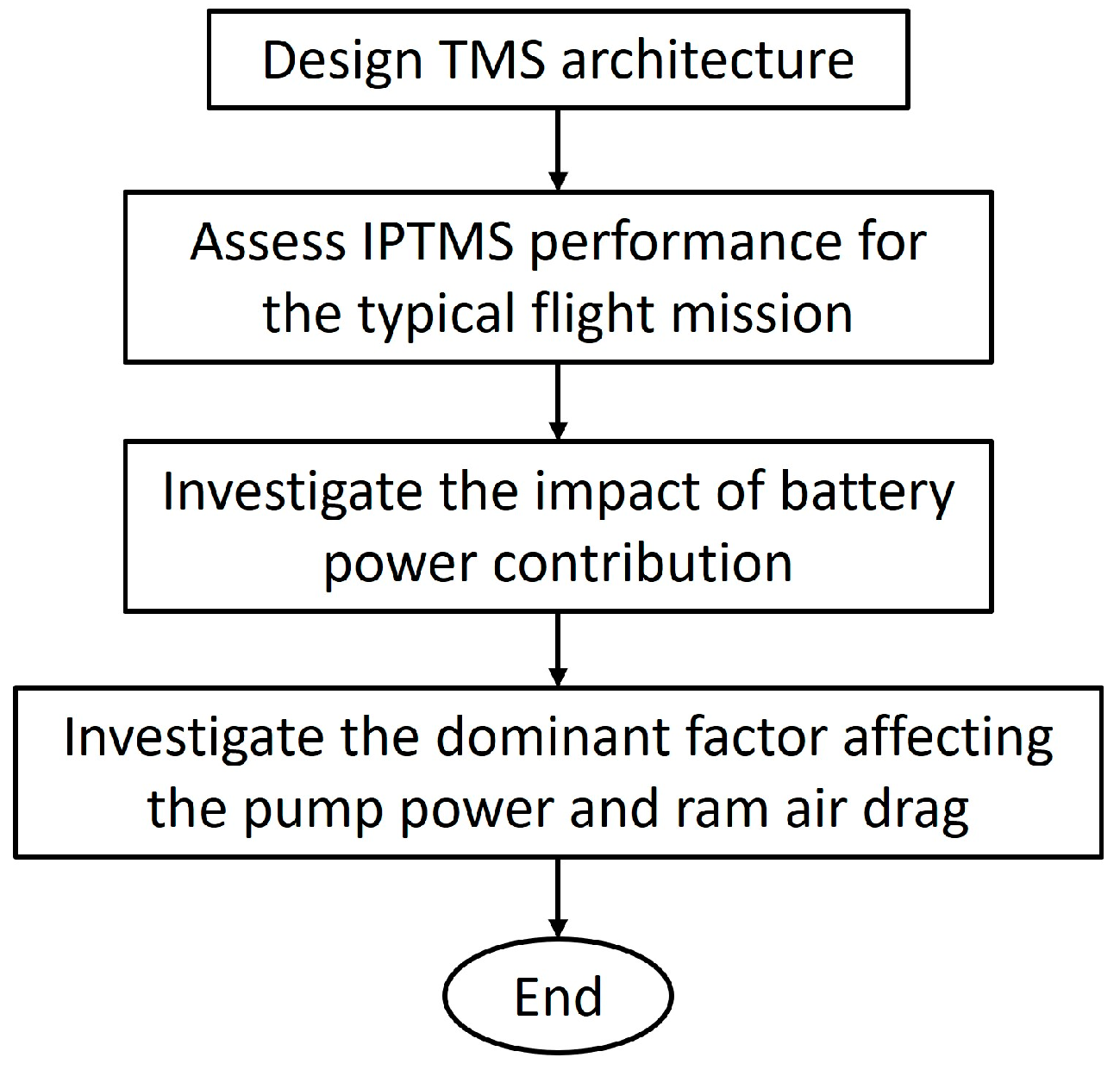
This study presents an IPTMS preliminary design for a parallel HEA, assessing the performance of active and passive cooling and temperature control for the gas turbine system and electrical propulsion system components under ISA conditions. Similarly to the authors’ previous work [18], the IPTMS performance is assessed for the typical mission profile (from take-off to climb), as the electrical propulsion system (EPS) only operates during these flight phases. As shown in Figure 1, we first designed a TMS architecture and corresponding cooling strategies, including three operating modes: (1) passive cooling, (2) active cooling, and (3) active temperature control modes. The IPTMS shifts modes depending on the cooling requirements during the flight mission. With the designed TMS, we then assessed the IPTMS performance during take-off and climb. The IPTMS performance was also assessed at two battery power (BP) utilization cases, which are 0% and 100% BP, to investigate the impact of battery contribution. A 0% BP means that the battery does not contribute to cooling power, and the cooling power comes from the engine-driven generators. At 100% BP, the battery provides all the cooling power. Through these assessments, we also analyzed the dominant factor affecting the coolant pumps’ required power and induced ram air drag of the overall TMS. This paper is organized as follows. Section 2 presents the methodology of the IPTMS preliminary design. Section 3 presents the case study. Section 4 contains the analysis of the IPTMS performance results. Finally, Section 5 concludes the paper and presents future work.
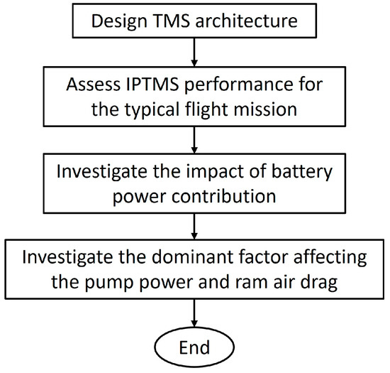
Figure 1.
Methodology flowchart.
2. Methodology of the IPTMS Preliminary Design
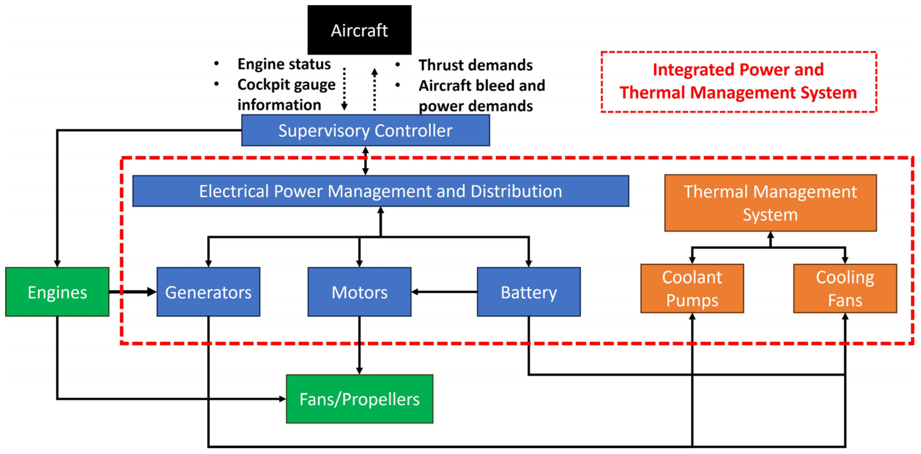
Figure 2 illustrates a typical IPTMS structure for a parallel HEA. In the parallel HEA, the propulsors, such as fans for propellers, are driven by the engines and motors. Additionally, the power for the motors is provided solely by the battery. When the electrical components operate, their heat is rejected by the TMS. To manage the heat, the components in the TMS, such as coolant pumps and cooling fans, require electric power, which can be provided by the engine-driven generators or the battery. Therefore, in the IPTMS, the power management system (PMS) needs to balance the power for propulsion and cooling and the contribution of cooling power between the generators and the battery. If fuel consumption and the generators’ heat increase significantly because the generators provide cooling power, more battery power contribution to cooling power is needed. At the same time, the PMS also needs to ensure that the battery state of charge remains above its minimum state of charge to avoid damage. Since both the PMS and the TMS influence IPTMS performance, it is essential to determine which domain offers the most potential for optimization during the preliminary design phase. If optimization within the PMS is required, a power management strategy must be implemented to balance battery power allocation between propulsion and cooling, thereby reducing heat generation and fuel consumption. Alternatively, if TMS optimization is necessary, the system’s architecture will need to be re-engineered, incorporating advanced cooling strategies such as phase-change cooling and the use of innovative coolants.
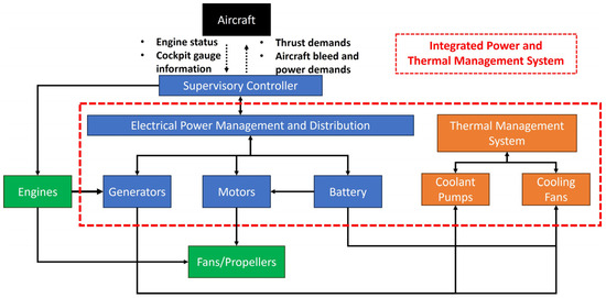
Figure 2.
Typical IPTMS structure for a parallel HEA, where the greed blocks represent propulsion, the blue blocks represent the power management system, and the orange blocks represent the thermal management system.
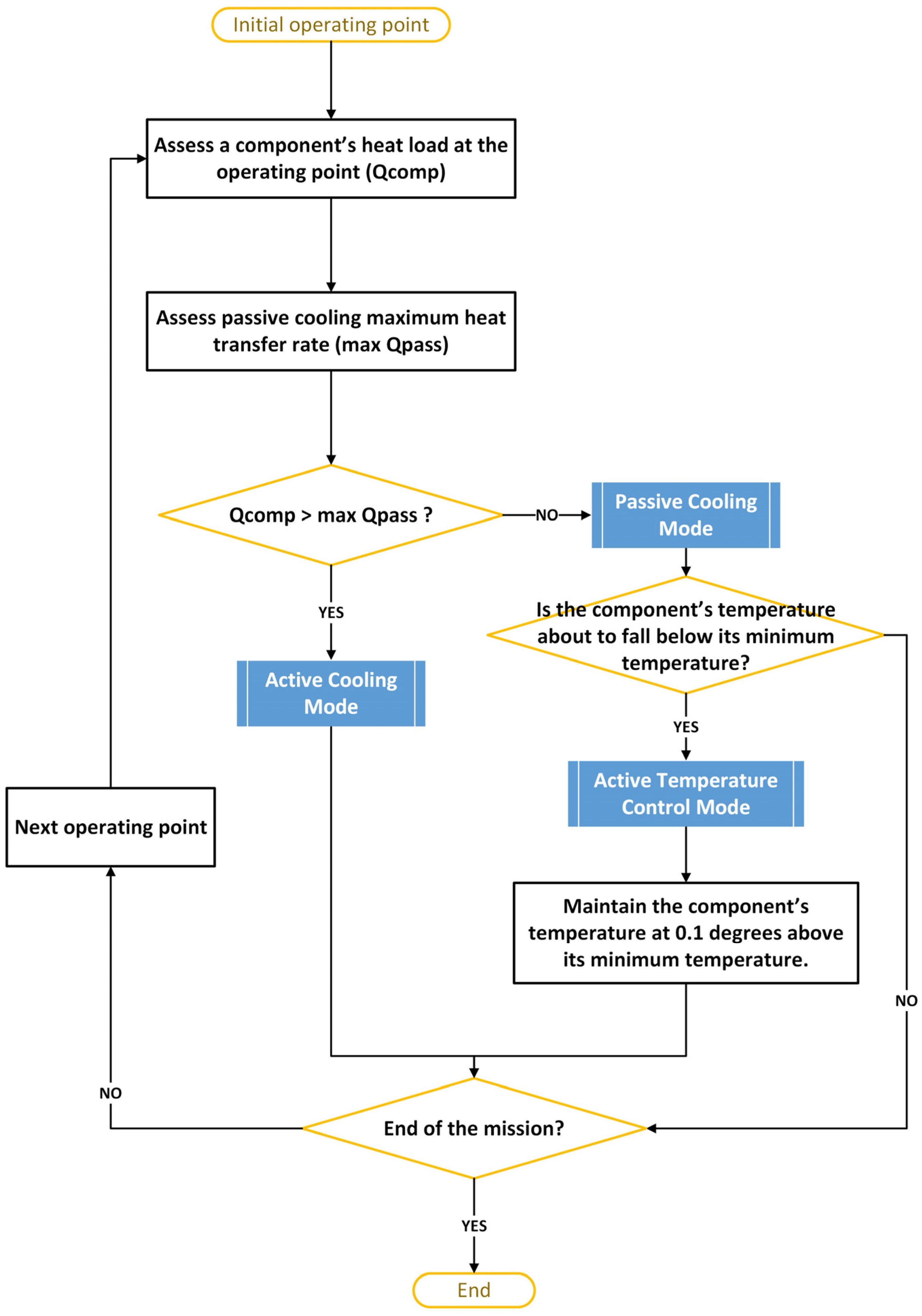
According to [18], we assumed the EPS component temperature limits, as shown in Table 1. To minimize the power for cooling while ensuring that the components operate within their temperature ranges, the IPTMS shifts between three operating modes across the flight mission: (1) active cooling, (2) passive cooling, and (3) temperature control modes, as shown in Figure 3. The IPTMS first evaluates the heat load and the maximum passive cooling heat transfer rate () of a component at the initial operating point. The maximum occurs when the component operates at its maximum temperature. Readers can refer to [18] for more information about the passive cooling performance assessment. When the heat load exceeds the maximum , passive cooling is not sufficient for the component at the current operating point. Therefore, active cooling is required, and the IPTMS shifts to active cooling mode. In contrast, when passive cooling is sufficient, the IPTMS operates in passive cooling mode, eliminating the need for coolant pump power. During passive cooling, the component temperature can potentially decrease below its minimum temperature. In this case, the IPTMS maintains the component temperature at 0.1 °C above its minimum to minimize power usage for temperature control. The IPTMS repeats this process from the initial operating point until the end of the mission.

Table 1.
EPS component temperature limits.

Figure 3.
IPTMS operation flowchart.
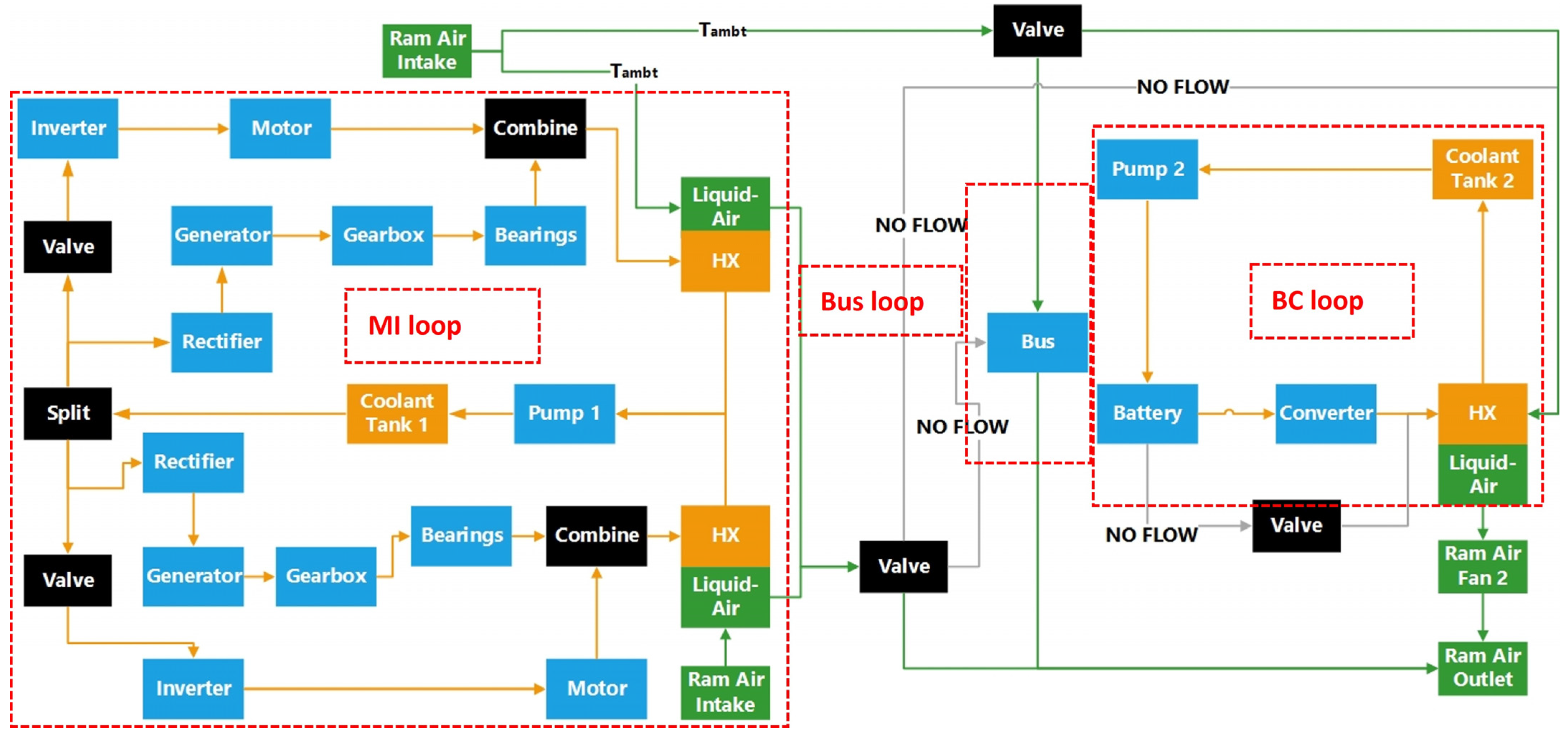
The IPTMS architecture has been presented in the authors’ previous work [18]. An overall TMS architecture at the active cooling mode is shown in Figure 4. The components are divided into three cooling loops: (1) motor-inverter (MI), (2) bus, and (3) battery-converter (BC) loops, according to their heat load magnitudes and installations. The grey vectors represent the inactive air or cooling paths for temperature control. During active temperature control, the coolant increases the component temperature, with the heat coming from the MI loop’s warm ram air. For the MI loop, we cooled the motors, inverters, and gas turbine system components in the same cooling loop, using the same coolant pump, coolant tank, and heat exchangers to save weight and volume by reducing TMS components. Traditionally, the gas turbine system components, such as gearboxes, bearings, and generators, are cooled by engine oil, which offers both cooling and lubrication functions. The valves in the MI loop control the coolant for the motors and inverters. When the EPS is not operating, the valves will be closed, and the MI loop will only cool the components in the gas turbine engine system, similarly to the traditional TMS. According to [19,20], we assumed the MI loop coolant tank’s initial outlet temperature to be 80 °C. After the initial operating point, the tank outlet temperature varies throughout the mission. Compared with other coolants, the engine oil temperature is higher to ensure its lubrication performance, as the oil viscosity decreases when the temperature drops. Additionally, the MI loop components can operate at high-temperature conditions, making the engine oil temperature assumption reasonable.
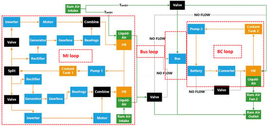
Figure 4.
Overall TMS architecture at the active cooling mode, where Tambt represents the ambient temperature, HX represents the heat exchanger, the blue blocks represent the electrical components, the green vectors represent the air flows, the orange vectors represent the coolant flows, and the grey vectors represent the hardware for inactive temperature control mode.
For the BC loop, PGW40 (a 40% mixture of propylene glycol and water) was selected as the coolant. The percentage was chosen based on the evaluation of different PGW percentages under various operating conditions, which is not included in this study. The BC loop coolant tank’s initial outlet temperature was assumed to be 30 °C, and the tank outlet temperature varies throughout the mission after the initial operating point. For the bus loop, the bus is cooled by ram air in an air duct. It is an open-loop air cooling system, without the need for fans, pumps, heat exchangers, and other TMS components, saving weight and volume.
3. Proposed Study
A parallel HEA configuration was designed for a baseline aircraft similar to the ATR72. The studied HEA consists of two 500 kW motors, a 263 kWh battery, and the associated converters and bus [18]. Since the EPS only operates during the take-off and climb phases, we assessed the IPTMS performance for this typical mission profile under ISA conditions, which was presented in [18].
4. Results Analysis
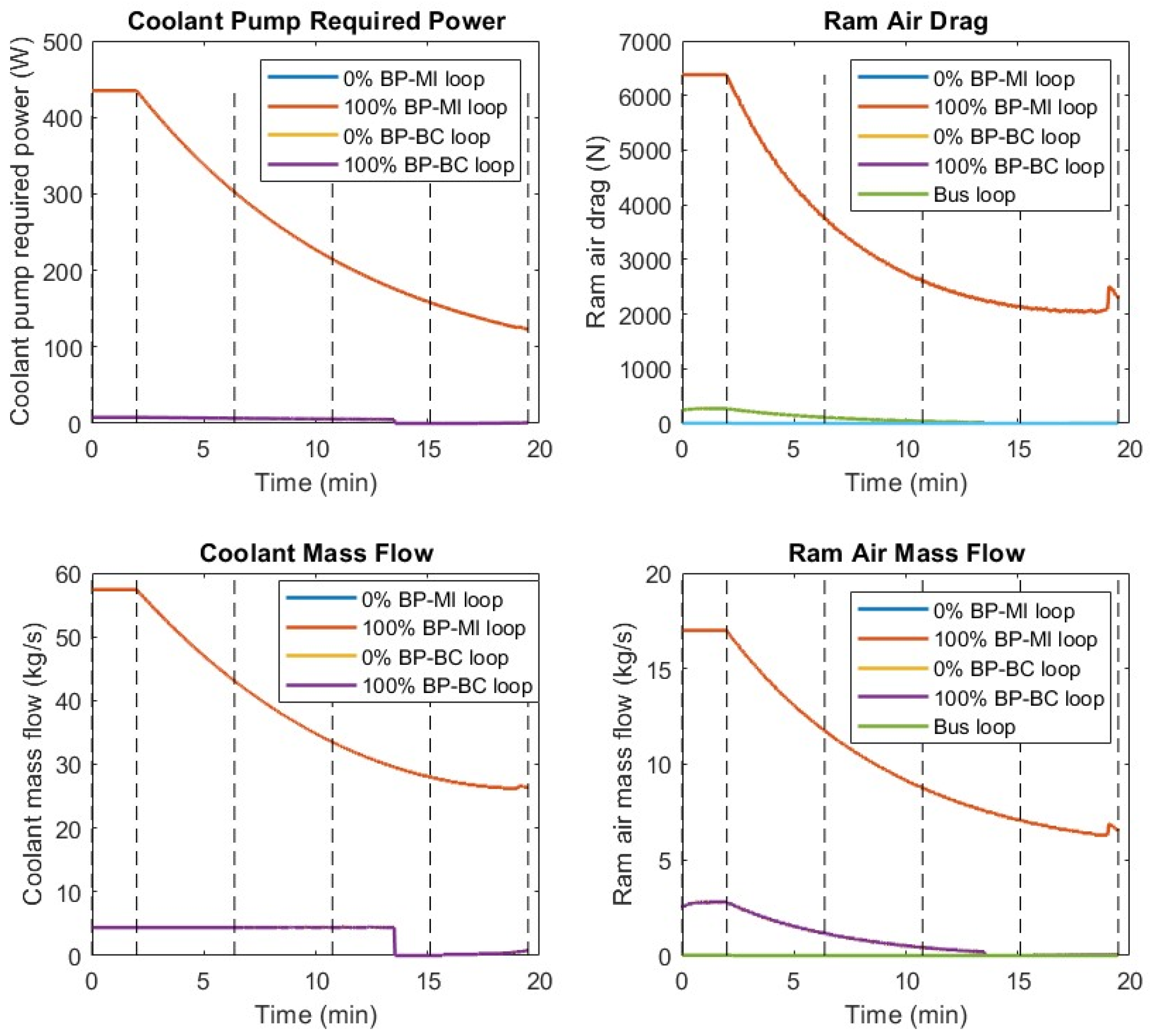
The EPS heat load analysis across the typical mission was conducted in [18]. To investigate how the battery power (BP) contribution affects the IPTMS performance, we assessed the required power of the coolant pump and ram air drag across the typical mission under two cases: (1) 0% BP and (2) 100% BP. At 0% BP, the battery does not contribute to the cooling power, which comes from the engine-driven generators. At 100% BP, the battery provides all the cooling power. Figure 5 illustrates the integration of active and passive cooling and temperature control under the 0% and 100% BP cases. Comparing these two conditions, it was found that the magnitude of BP contribution does not affect TMS performance because the total battery power (max 950 kW) is much greater than the required cooling power (max 443 W). Since the battery still retains about 20% state of charge at the top of climb, it can fully support the cooling power. At the end of the mission, the ambient temperature decreases to 18 °C, and the battery power output decreases toward zero, causing the BC loop to generate more warm air for temperature control. Consequently, the ram air drag of the MI loop slightly increases toward the mission’s end. Comparing the required cooling power and induced ram air drag of the three cooling loops, it was found that the MI loop is the dominant factor affecting TMS performance, contributing about 97% of pump power and 98% of induced drag to the overall TMS. This is due to the low thermal conductivity of engine oil. Therefore, three potential solutions to optimize the TMS are as follows:
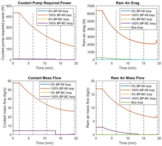
Figure 5.
Coolant pump power and ram air drag for MI (motor-inverter), BC (battery-converter), and bus loops at 0% and 100% BP (battery power) cases, where the dashed lines represent the flight segments in the following sequence: take-off, start-climb, early-climb, mid-climb, late-climb, and top of climb.
- Optimize the MI loop cooling strategy, such as using phase-change cooling or other efficient cooling strategies.
- Split the MI loop into two loops, cooling the motors and inverters in one loop and the gas turbine engine system components in the other loop.
- Select another coolant with higher thermal conductivity for cooling the motors and the inverters.
5. Conclusions and Future Work
This study presents a preliminary integrated power and thermal management system (IPTMS) design for a parallel hybrid-electric aircraft (HEA), examining both active and passive cooling as well as temperature control under International Standard Atmosphere (ISA) conditions. Simulations were conducted across a typical mission profile, from take-off to the top of the climb, with the following key findings:
- The magnitude of battery power contribution to cooling power does not significantly impact thermal management system (TMS) performance due to the large difference between the total battery power (maximum 950 kW) and the required cooling power (maximum 443 W).
- The battery can fully support cooling power, helping to reduce fuel consumption, while maintaining 20% state of charge at the top of the climb.
- The motor-inverter loop is the primary driver of TMS performance, accounting for 97% of pump power and 98% of induced drag.
To further optimize the IPTMS design, future work will focus on refining TMS cooling strategies, such as employing phase-change cooling and advanced coolants, or separating cooling loops. Additionally, IPTMS performance will be evaluated under hot- and cold-day conditions.
Author Contributions
Writing—original draft, methodology, formal analysis, software, and investigation, Z.O.; writing—review and editing, supervision, and investigation, T.N.; writing—review and editing, supervision, and investigation, S.J.; writing—review and editing, supervision, and investigation, E.P. All authors have read and agreed to the published version of the manuscript.
Funding
This research received no external funding.
Institutional Review Board Statement
Not applicable.
Informed Consent Statement
Not applicable.
Data Availability Statement
The raw data supporting the conclusions of this article will be made available by the authors on request.
Conflicts of Interest
The authors declare no conflicts of interest.
References
- ACARE. Fly the Green Deal—Europe‘s Vision for Sustainable Aviation; Publications Office of the European Union: Luxemburg, 2022. [Google Scholar]
- NASA. Strategic Implementation Plan 2017 Update; NASA: Washington, DC, USA, 2017.
- Rheaume, J.M.; Lents, C.E. Commercial Hybrid Electric Aircraft Thermal Management Sensitivity Studies. In Proceedings of the AIAA Propulsion and Energy 2020 Forum, New Orleans, LA, USA, 26–28 August 2020; American Institute of Aeronautics and Astronautics: Reston, VA, USA, 2020; pp. 1–6. [Google Scholar]
- Roberts, R.; Eastbourn, S. Vehicle Level Tip-to-Tail Modeling of an Aircraft. Int. J. Thermodyn. 2014, 17, 107–115. [Google Scholar] [CrossRef]
- Ganev, E.; Koerner, M. Power and Thermal Management for Future Aircraft. In Proceedings of the SAE 2013 Aerotech Congress and Exhibition, Montreal, QC, Canada, 24–26 September 2013. [Google Scholar]
- Aerospace Technology Institute. Accelerating Ambition Foreword Overview of Priorities Air Transport Vision Market Opportunity Vehicles Propulsion and Power Systems Aerostructures Cross-Cutting Enablers Economic Impact Closing Remarks; Aerospace Technology Institute: Cranfield, UK, 2019. [Google Scholar]
- Misley, A.A.; D’Arpino, M.; Ramesh, P.; Canova, M. A Real-Time Energy Management Strategy for Hybrid Electric Aircraft Propulsion Systems. In Proceedings of the AIAA Propulsion and Energy 2021 Forum, Denver, CO, USA, 11–13 August 2021; American Institute of Aeronautics and Astronautics: Reston, VA, USA, 2021. [Google Scholar]
- Kellermann, H.; Lüdemann, M.; Pohl, M.; Hornung, M. Design and Optimization of Ram Air–Based Thermal Management Systems for Hybrid-Electric Aircraft. Aerospace 2020, 8, 3. [Google Scholar] [CrossRef]
- Zhao, C.; Clarke, M.; Kellermann, H.; Verstraete, D. Liquid Cooling Systems for Batteries of Electric Vertical Takeoff and Landing Aircraft. J. Aircr. 2024, 61, 667–683. [Google Scholar] [CrossRef]
- Shi, M.; Sanders, M.; Alahmad, A.; Perullo, C.; Cinar, G.; Mavris, D.N. Design and Analysis of the Thermal Management System of a Hybrid Turboelectric Regional Jet for the NASA ULI Program. In Proceedings of the AIAA Propulsion and Energy 2020 Forum, New Orleans, LA, USA, 26–28 August 2020; American Institute of Aeronautics and Astronautics: Reston, VA, USA, 2020; pp. 1–24. [Google Scholar]
- Adler, E.J.; Brelje, B.J.; Martins, J.R.R.A. Thermal Management System Optimization for a Parallel Hybrid Aircraft Considering Mission Fuel Burn. Aerospace 2022, 9, 243. [Google Scholar] [CrossRef]
- Kim, J.H.; Kwon, K.S.; Roy, S.; Garcia, E.; Mavris, D. Megawatt-Class Turboelectric Distributed Propulsion, Power, and Thermal Systems for Aircraft. In Proceedings of the 2018 AIAA Aerospace Sciences Meeting, Kissimmee, FL, USA, 8–12 January 2018. [Google Scholar]
- Rheaume, J.M.; MacDonald, M.; Lents, C.E. Commercial Hybrid Electric Aircraft Thermal Management System Design, Simulation, and Operation Improvements. In Proceedings of the AIAA Propulsion and Energy 2019 Forum, Indianapolis, IN, USA, 22–24 August 2019; American Institute of Aeronautics and Astronautics: Reston, VA, USA, 2019. [Google Scholar]
- Schnulo, S.L.; Chapman, J.W.; Hanlon, P.; Hasseeb, H.; Jansen, R.; Sadey, D.; Sozer, E.; Jensen, J.; Maldonado, D.; Bhamidapati, K.; et al. Assessment of the Impact of an Advanced Power System on a Turboelectric Single-Aisle Concept Aircraft. In Proceedings of the AIAA Propulsion and Energy 2020 Forum, New Orleans, LA, USA, 26–28 August 2020; American Institute of Aeronautics and Astronautics: Reston, VA, USA, 2020; pp. 1–18. [Google Scholar]
- Heersema, N.; Jansen, R. Thermal Management System Trade Study for SUSAN Electrofan Aircraft. In Proceedings of the AIAA SCITECH 2022 Forum, San Diego, CA, USA, 3–7 January 2022; American Institute of Aeronautics and Astronautics: Reston, VA, USA, 2022. [Google Scholar]
- Coutinho, M.; Afonso, F.; Souza, A.; Bento, D.; Gandolfi, R.; Barbosa, F.R.; Lau, F.; Suleman, A. A Study on Thermal Management Systems for Hybrid–Electric Aircraft. Aerospace 2023, 10, 745. [Google Scholar] [CrossRef]
- Nyamagoudar, V.; P R, N.; Balasubrahmanyam, M.; Vanka, S.; Gattu, R.; Abuheiba, A.; Jha, R.K. Hybrid Cooling System for Thermal Management in Electric Aerial Vehicles; SAE Technical Paper 2024-26-0468; SAE International: Warrendale, PA, USA, 2024. [Google Scholar] [CrossRef]
- Ouyang, Z.; Nikolaidis, T.; Jafari, S. Integrated Power and Thermal Management System for A Hybrid-Electric Aircraft: Integrated Modeling and Passive Cooling Analysis. J. Eng. Gas. Turbine Power 2024, 146, 111024. [Google Scholar] [CrossRef]
- Rheaume, J.; Lents, C.E. Design and Simulation of a Commercial Hybrid Electric Aircraft Thermal Management System. In Proceedings of the 2018 AIAA/IEEE Electric Aircraft Technologies Symposium, Cincinnati, OH, USA, 12–14 July 2018; American Institute of Aeronautics and Astronautics: Reston, VA, USA, 2018. [Google Scholar]
- Chapman, J.W.; Schnulo, S.L.; Nitzsche, M.P. Development of a Thermal Management System for Electrified Aircraft. In Proceedings of the AIAA SCITECH 2020 Forum, Orlando, FL, USA, 6–10 January 2020; American Institute of Aeronautics and Astronautics: Reston, VA, USA, 2020. [Google Scholar]
Disclaimer/Publisher’s Note: The statements, opinions and data contained in all publications are solely those of the individual author(s) and contributor(s) and not of MDPI and/or the editor(s). MDPI and/or the editor(s) disclaim responsibility for any injury to people or property resulting from any ideas, methods, instructions or products referred to in the content. |
© 2025 by the authors. Licensee MDPI, Basel, Switzerland. This article is an open access article distributed under the terms and conditions of the Creative Commons Attribution (CC BY) license (https://creativecommons.org/licenses/by/4.0/).