Abstract
This work analyzes the spectrum sharing scenarios of the evolution of terrestrial and non-terrestrial networks at a European and international level. The evolution and interoperability of terrestrial and non-terrestrial networks are key elements in providing the new services expected by 6G. With the growing demand of the spectrum, inter-system sharing, which involves sharing between different radiocommunication applications, is becoming increasingly important. Technical conditions to share the spectrum between a terrestrial fixed service operating through Point-to-Multipoint links and a fixed satellite service at 28 GHz are assessed and presented in this paper. The methodology to evaluate the coexistence conditions can be easily extended to other spectrum sharing scenarios, both between terrestrial networks and between terrestrial and non-terrestrial networks.
1. Introduction
In order to meet the requirements in terms of the coverage, capacity and user experience of various emerging 6G applications and new use cases and usage scenarios, interworking between terrestrial and non-terrestrial networks is increasingly fundamental. The joint evolution and interoperability of both IMT and non-IMT (including RLAN and broadcast) terrestrial networks and non-terrestrial networks, including satellite communication systems, HIBSs (high-altitude platform stations as IMT base stations) and UASs (Unmanned Aircraft Systems), are considered key elements in providing the expected 6G services.
The definition and evaluation process for the new IMT-2030 technology is underway within the ITU (International Telecommunication Union). In November 2023, the ITU approved Recommendation ITU-R M.2160 on the “IMT-2030 Framework” [1], which defines the overall framework and objectives of IMT towards 2030 and beyond, to guide future developments of IMT, including the evolution of the radio access network. In this context, the framework and overall objectives of future IMT development described in Recommendation ITU-R M.2083 [2] and of future technology trends included in Report ITU-R M.2516-0 [3] were taken into account. In the period 2024–2027, the ITU will define the relevant requirements and evaluation criteria for potential new radio IMT interface technologies. In May 2024, the ITU also finalized Report ITU-R M.2541 [4] on the technical feasibility of IMT in bands above 100 GHz. The report includes information on propagation mechanisms and channel models, as well as newly developed technology enablers such as active and passive components, antenna techniques, deployment architectures, and the results of simulations and performance tests. This report complements Report ITU-R M.2376 [5], containing studies on IMT usage in the frequency range of 6–100 GHz.
Agenda item 1.7 of the World Radio Conference 2027 (WRC-27) invites us to perform sharing and compatibility studies to ensure the protection of services to which the frequency band is already allocated on a primary basis and possibly develop technical conditions for the use of IMT in the frequency range of 4–15 GHz [6]. The possible IMT identification could make these new frequency bands suitable candidates for 6G deployment.
The evolution of terrestrial systems also includes the use of RLANs/WASs (radio local area networks/wireless access systems) license-exempt networks; the WiFi 6E and WiFi 7 standards, designed to work in the 6 GHz band, can implement higher bandwidths to achieve the required high throughput and low latency to serve specific 6G use cases (i.e., automotive, virtual reality, augmented reality). The use of WiFi technology to provide the evolved services envisaged for 6G is facilitated by the European initiative ’European Digital Decade Policy Programme 2030—“Gigabit for everyone”’, [7] which provides gigabit FTTH (fiber to the home) distribution up to the network termination point. WiFi 6E and WiFi 7 technologies are therefore a good solution to complement gigabit fiber connections.
The frequency band 6425–7125 MHz has been identified for IMT at the last World Radio Conference WRC-23. The IMT identification footnote includes recognition that these frequency bands can be also used for WASs/RLANs. The European Commission is finalizing the mandate for the CEPT (European Conference of Postal and Telecommunications Administrations) to study the feasibility of and to develop harmonized technical conditions for the efficient use, on a shared basis, of the 6425–7125 MHz (‘upper 6 GHz’) frequency band for the most recent and future technologies for terrestrial systems capable of providing wireless broadband (WBB) electronic communications services (ECSs) and for wireless access systems including radio local area networks (WASs/RLANs).
In parallel, satellite networks are evolving, and new advanced services are provided through both GSO (Geostationary Satellite Orbit) and especially NGSO (Non-Geostationary Satellite Orbit) in low orbit (e.g., VLEO, LEO and MEO) systems using different frequency bands. Direct-to-cell (D2C) communications are meant to provide satellite-based connectivity to mass-market terrestrial mobile handsets with the aim of providing additional coverage mainly in unserved rural areas. The implementation of D2C services is expected to use MSS (Mobile Satellite Service) frequency bands. Moreover, the WRC-27 agenda item 1.13 [6] foresees the study of possible spectrum allocation to the MSS for direct connectivity between space stations and IMT user equipment in the IMT frequency range. The European Commission has requested the Radio Spectrum Policy Group (RSPG) to form an opinion on the EU-level policy approach for the use of satellite direct-to-device connectivity.
In the framework where new 6G services are expected to be developed, no single frequency range meets all of the spectrum requirements needed to implement 6G services.
The RSPG has recently launched a public consultation on 6G strategic vision [8], aiming to identify the spectrum needs to facilitate the initial launch and operation of 6G networks/services from 2030. The RSPG intends to launch a 6G spectrum roadmap during 2026–2027 in order to identify which frequency band(s) should be made available for the 6G mass market. In order to improve spectral efficiency, the spectrum for the new 6G systems is expected to be shared between various services and users. It is therefore very important to plan actions that promote the shared use of the spectrum, both between terrestrial networks (TN) and between terrestrial and non-terrestrial networks (TN-NTN).
The technical analysis presented in this work represents the continuation of coexistence studies between terrestrial and non-terrestrial systems in the 27.5–29.5 GHz band carried out in [9]. In [9], results of a coexistence analysis between fixed-satellite-service Earth-to-space (FSS E-S) interferer and fixed-service (FS) Wireless Local Loop Point-to Point (FS WLL P-P) victim systems have been presented. In this paper, we extend the coexistence analysis to evaluate the coexistence condition between FSS E-S and FS WLL Point-to-Multipoint systems. The adopted methodology and the general conclusions derived regarding spectrum sharing conditions can be easily extended to other coexistence analyses between different services.
2. Case Study: Spectrum Sharing in the 28 GHz Band
Space-based connectivity at 28 GHz (i.e., 27.5–29.5 GHz) is increasingly important in Europe with an ever-growing number of Earth satellite gateways.
In the ITU Radio Regulation [10], the 27.5–29.5 GHz band is allocated on a co-primary basis to the fixed service (FS), fixed satellite service Earth-to-space (FSS E-S) and to the mobile service (MS). In Europe, the regulatory framework for the use of the 28 GHz band is provided in [11]. In Italy, the fixed service operates through WLL (Wireless Local Loop) technology with P-P (Point-to-Point) and P-MP (Point-to-Multipoint) connections. To facilitate coordination at the national level, the study of the technical conditions that guarantee the protection of the FS system becomes necessary. At the international level, the protection and coordination of the satellite component of the FSS system is managed within the ITU.
In [9], the coexistence scenarios between the FSS and FS in the 27.5–29.5 GHz band have been identified and the coexistence conditions between the FSS E-S system and the FS WLL P-P system have been evaluated. In this paper, the methodology already developed for the coexistence study between FSS E-S (GSO) systems and FS WLL P-P systems has been extended and adapted to the coexistence scenario between the FSS E-S (GSO) and the FS WLL P-MP systems.
WLL P-MP systems allow for the connection of a central station (CS) to several terminal stations (TSs), thus being able to provide wireless broadband services. Figure 1 shows the coexistence scenario that will be analyzed in this work. In the coexistence analysis between the FSS Earth station and FS WLL P-MP link, the protection of both the CS and TS must be guaranteed. The final coexistence conditions take into account the joint results of the two analyses, considering that the protection of the TS must be evaluated on all locations (pixels) of the FS coverage area where it is assumed that a P-MP receiver could be present.
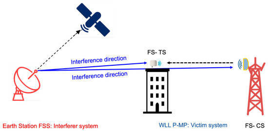
Figure 1.
Coexistence scenario: FSS E-S interfering FS WLL P-MP.
The general methodology for carrying out coexistence studies has been described in [9]. The methodology applied in this work is reported, for convenience, below.
The methodology adopted to evaluate the interference on FS WLL P-MP links due to FSS Earth stations is based on the Minimum Coupling Loss (MCL) approach [11,12,13] taking into account the long-term FS protection criterion based on the I/N ratio (interference-to-noise ratio). The I/N ratio in dB is evaluated with the following formula:
I/N (∆f, d, ϑ1, ϑ2) = Pt + Att(∆f) + Gt(ϑ1) + Gr(ϑ2) − PL(d) − N
In the above formula, Pt is the transmitted power (dBm) of the interferer that in the analyzed scenario is represented by the FSS E-S Earth station; ∆f is the frequency separation (in MHz) between the carrier frequencies of the interferer and the victim systems; Att(∆f) is the Net Filter Discrimination (NFD) that must be computed according to the considered band and service; Gt(ϑ1) and Gr(ϑ2) are, respectively, the gains (dBi) of the FSS interferer antenna at angle ϑ1 and of the FS WLL CS/TS victim antenna at angle ϑ2 between the interfering system site and victim system site; PL(d) is the path loss attenuation (dB) due to the propagation along distance d (km); and N is the noise level (dBm) of the victim receiver.
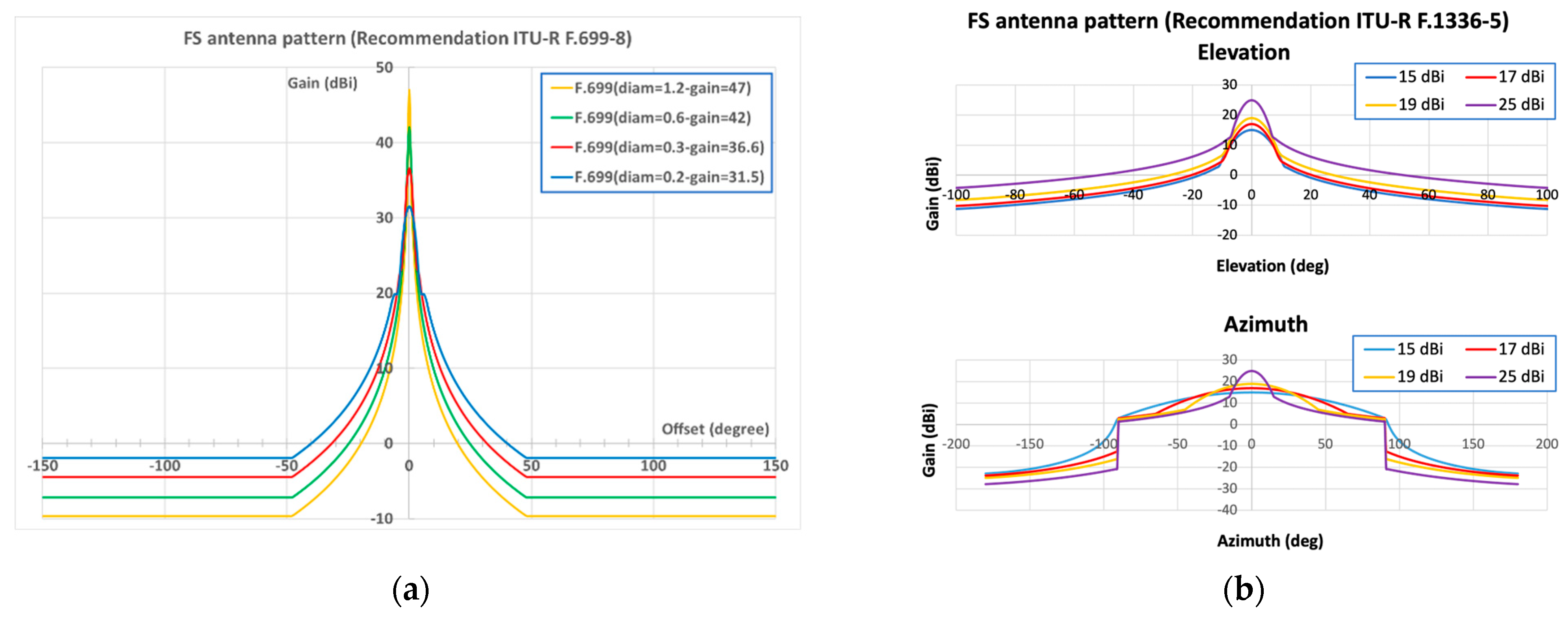
In this paper, the identification of the technical conditions to ensure coexistence between the FSS E-S (GSO) and FS WLL P-MP systems has been studied, analyzing the co-channel (i.e., Att(∆f) = 0 dB) coexistence scenario. The antenna pattern of the FSS transmitter follows Recommendation ITU-R S.465-6 [14] as used in the coexistence analysis in [9]. Figure 2a shows the antenna pattern of the receiving FS WLL TS that follows Recommendation ITU-R F.699-8 [15] and Figure 2b shows the antenna pattern of the receiving FS WLL CS that follows Recommendation ITU-R F.1336-5 [16].

Figure 2.
FS WLL antenna pattern: (a) FS WLL TS antenna pattern (Recommendation ITU-R F.699-8); (b) FS WLL CS antenna pattern (Recommendation ITU-R F.1336-5).
The antenna patterns in Figure 2 have been obtained with the FUB sharing tool [17,18]: the diagram of the FS WLL TS receiver in Figure 2a is plotted for different values of the antenna diameter which correspond to different antenna gains; the diagram of the FS WLL CS receiver in Figure 2b is plotted for different maximum gains of the FS P-MP antenna. Figure 2b shows the antenna pattern in the elevation and azimuthal planes.
The propagation model used in the simulations is based on Recommendation ITU-R P.452-16 [19] at 20% of the time (i.e., the interference is characterized as the interference power that is exceeded by 20% of the time at the victim receiver input), including the effect of the clutter in the suburban environment. This propagation model is commonly used at the international level for coexistence studies (e.g., [13,20,21,22]). For each CS and TS receiver, the I/N ratio is evaluated, and the obtained value is compared with the protection threshold (I/N max). This methodology is usually used at the ITU and CEPT level for the evaluation of the technical conditions of coexistence between different systems. In order to carry out the simulation analyses, this methodology has been implemented in the proprietary sharing tool of the Fondazione Ugo Bordoni (FUB) that is used in many projects, both at a national and international level, commissioned to the FUB by the Italian Administration. The validation of the implemented methodology has been performed considering the results contained in the ECC Report 304 [13] as a benchmark.
3. Coexistence Analysis Results
In this section, the results of the coexistence conditions between the FSS system and the FS WLL P-MP system are shown, considering the impact of the FSS Earth station transmission on both the receiving TS and the receiving CS. Since, in a P-MP link, the position of the TS is not always known, the coexistence analysis has been performed assuming a TS receiver located on all of the pixels of the WLL P-PM link coverage area. The calculation was performed considering only one TS receiver. The same evaluation has been repeated on all of the TS receivers present in the P-MP link coverage area.
The following results of the coexistence analyses are presented:
- Regarding separation distances between FS P-MP CS and FSS Earth station as a function of FSS Earth station elevation angle for different shielding effects, the calculations take into account that for antennas located on the roof of a building, shielding up to 30 dB can be provided when a roof parapet or safety wall at the building borders exists or when the antenna is mounted on the side of a roof or building.
- The separation distances between the FS P-MP CS/TS and the FSS Earth station for different azimuth offsets of the FS system have been evaluated.
- An evaluation of the exclusion zone around the FS WLL CS and the receiver around the FS WLL TS was performed exclusion zone is the geographical area within FSS licensees is not allowed to have FSS transmitters.
3.1. Separation Distances Between FS CS and FSS vs. FSS Earth Station Elevation Angle
The evaluation of the separation distance between the FS CS and FSS Earth station has been performed considering the following technical characteristics of FSS transmitters (Table 1) and the FS CS receiver (Table 2):

Table 1.
Simulation parameters of FSS E-S system.
Table 2.
Simulation parameters of FS WLL CS.
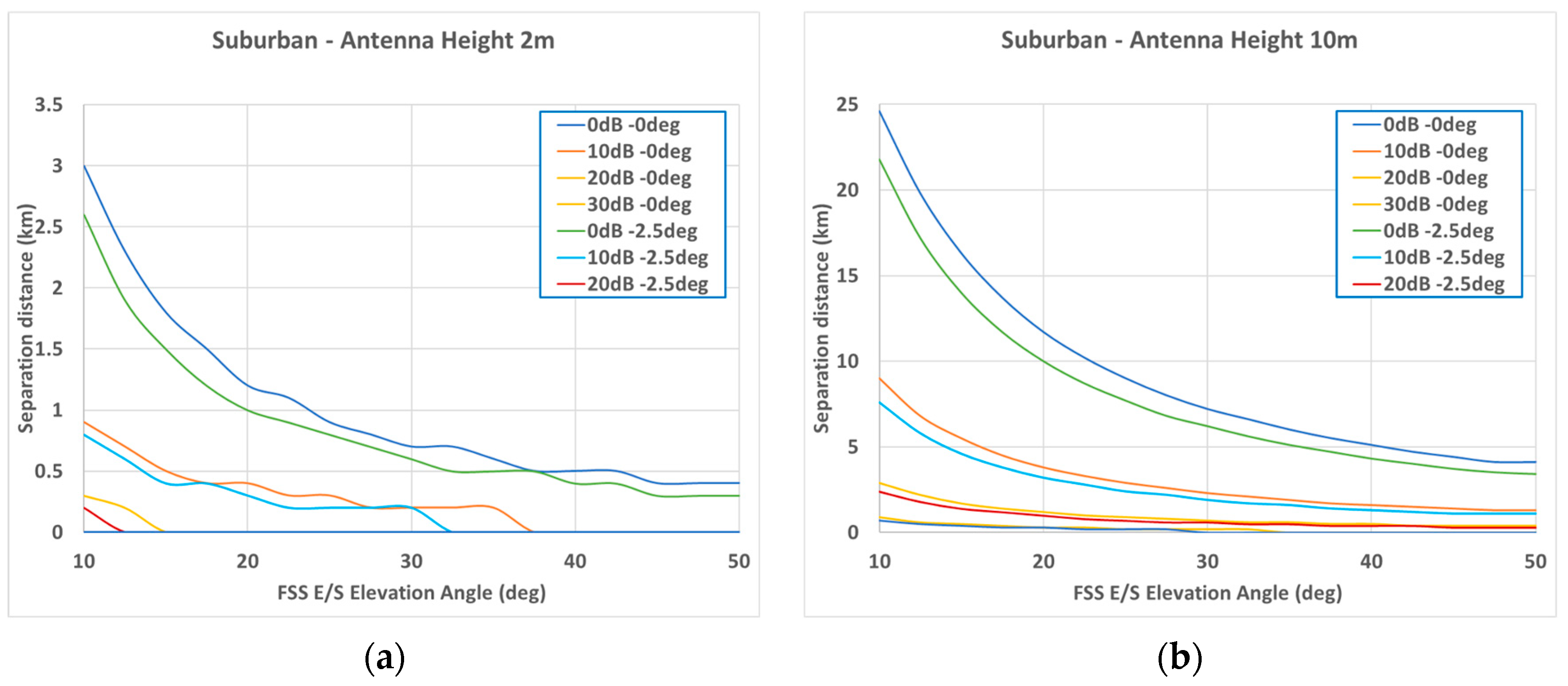
Simulations were implemented assuming that the FSS transmitter and the FS receiver were aligned in the azimuthal plane, and therefore no azimuthal off-axis discrimination was applied in the calculations. Figure 3 shows the separation distance results as a function of the FSS elevation angles for different values of shielding factors (0–30 dB) and FS elevations of 0° and 2.5°, assuming that the FSS antenna is installed in a suburban environment at 2 m (Figure 3a) and 10 m (Figure 3b).
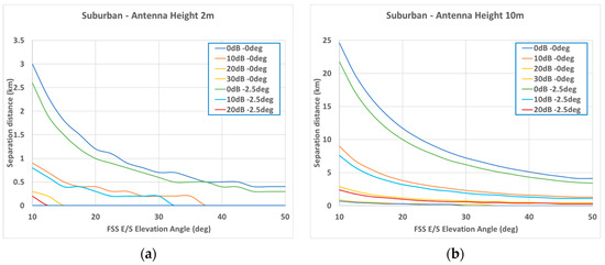
Figure 3.
Nominal separation distance between FSS ES transmitter (1.8 m) and FS P-MP CS receiver for suburban deployment: (a) FSS ES antenna height is at 2 m; (b) FSS ES antenna height is at 10 m.
The range of nominal separation distance depends on the shielding factor, the FSS ES antenna height and the off-axis angle between the FS and FSS ES system. The maximum value of this range represents the case of a 0 dB shielding factor and FSS ES elevation angle of 10°, whereas the minimum value represents the case of a 30 dB shielding factor and FSS ES elevation angle of 50°. As can be seen from the figures above, when the FSS ES elevation angle increases, the nominal separation distance decreases significantly.
3.2. Separation Distances Between FS P-MP CS/TS and FSS Earth Station vs. Different Azimuth Offset of the FS System
The results presented in this section show the separation distances obtained between the victim system receiver FS and an FSS Earth station when the azimuth offset is applied on the FS sides, meaning that the FSS signal is not arriving at the main lobe of the FS antenna.
The separation distances have been evaluated both between the FSS Earth station and the FS CS and between the FSS Earth station and the FS TS. The following technical characteristics of the FSS and FS systems have been considered:
- FSS: an antenna diameter of 0.75 m, elevation angle of 10 degree, antenna height of 10 m, Pt = 51.28 W, antenna gain = 43.9 dBi and bandwidth = 80 MHz.
- FS CS: an antenna height of 30 m, antenna gains of 15 dBi and 25 dBi, elevation angle of 0 degrees and bandwidth of 28 MHz.
- FS TS: an antenna height of 30 m, antenna gain of 42 dBi, elevation angle of 0 degrees and bandwidth of 28 MHz.
The following tables (Table 3, Table 4 and Table 5) show the separation distances in km when the FSS signal arrives at different azimuth offsets of the FS and FSS systems considering an FS TS receiver and an FS CS receiver with antenna gains of 15 dBi and 25 dBi, respectively.
Table 3.
Separation distance between FSS Earth station and FS TS.
Table 4.
Separation distance between FSS Earth station and FS CS (FS CS antenna gain 15 dBi).
Table 5.
Separation distance between FSS Earth station and FS CS (FS CS antenna gain 25 dBi).
The separation distances shown in Table 4 and in Table 5 that refer to the coexistence between the FSS and FS CSs decrease more slowly than the ones in Table 3 that have been obtained considering an FS TS victim receiver. Starting from the case where the FS and the FSS are aligned in the azimuth to an FS azimuth of 90 degrees, the separation distances decrease from 44.3 km to 0.3 km, from 34.3 km to 19 km and from 38.3 km to 16 km in Table 3, Table 4 and Table 5, respectively.
3.3. Evaluation of Exclusion Zones Around the FS P-MP CS Receiver
Here, the exclusion zones around the FS victim receivers have been evaluated considering a flat terrain (red area) and an example of actual terrain elevation (green area). The exclusion areas have been calculated both around the FS TS and around the FS CS considering that the FSS transmitter and the FS receiver were aligned in the azimuthal plane. The following technical characteristics of the FSS and FS systems have been taken into account:
- FSS: an antenna diameter of 1.8 m, elevation angle of 10 degrees, antenna height of 10 m, Pt = 25.7 W, antenna gain = 52.91 dBi and bandwidth = 320 MHz
- FS CS: an antenna height of 15 m, antenna gain of 15 dBi, elevation angle of 0 degrees and bandwidth of 28 MHz.
- FS TS: an antenna height of 15 m, antenna gain of 42 dBi, elevation angle of 0 degrees and bandwidth of 28 MHz.
As shown in Figure 4, the effect of the terrain clearly reduces the extension of the exclusion area. In Figure 4a, the geographical area varies from 175 km2 considering flat terrain to 12.7 km2 taking into account the terrain elevation; in Figure 4b, the geographical area varies from 292 km2 considering flat terrain to 27.3 km2 taking into account the terrain elevation. Comparing the shapes of the exclusion areas around the FS TS and around the FS CS, the effect of the antenna diagram is clear: since the FS TS antenna is more directive, the exclusion area is more lengthened than the one resulting from the coexistence analysis on the FS CS receiver, which implements a sectoral antenna.
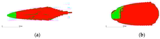
Figure 4.
Exclusion zones around FS P-MP receivers: red area represents flat terrain and green area represents actual terrain elevation. (a) Exclusion zone around FS TS; (b) exclusion zone around FS CS.
4. Conclusions
This paper analyses the coexistence between the GSO FSS E-S and the FSS WLL P-MP systems operating at 28 GHz. In order to evaluate the coexistence between an FSS Earth station and an FS P-MP link, the protection criterion has to be satisfied both at the CS receiver and at the TSs operating in the serving area of the FS CS. Some examples of the results obtained with the FUB sharing tool have been shown, considering the effect of the transmission of the FSS system on the FS CS and TS receivers. The results show that in the case of the FS CS victim receiver, the separation distances between the FSS and FS systems decreases more slowly with respect to the separation distance between the FSS and FS TS victim receiver. This is due to the antenna diagram of the FS CS. The effect of shielding on the FSS side has been also evaluated as a passive mitigation technique that can protect existing FS links; the presence of shielding can provide an attenuation of up to 30 dB that can considerably decrease the separation distances between the interfere FSS system and the receiver FS system. The analysis carried out aims to provide general indications that can be useful to operators and administrations to coordinate the development of networks.
Author Contributions
Conceptualization, methodology, validation, investigation, writing—original draft preparation, writing—review and editing, supervision, V.P., M.F., C.C. All authors have read and agreed to the published version of the manuscript.
Funding
This research received no external funding.
Institutional Review Board Statement
Not applicable.
Informed Consent Statement
Not applicable.
Data Availability Statement
Data are contained within the article.
Acknowledgments
This work was partially supported by the European Union under the Italian National Recovery and Resilience Plan (NRRP) of NextGenerationEU, partnership on ’Telecommunications of the Future’ (PE00000001—program RESTART). This work has also been carried out in the framework of the agreement between the Ministry of Enterprises and Made in Italy and Fondazione Ugo Bordoni—Project ’Studio sulle prospettive di impegno delle bande WLL’.
Conflicts of Interest
The authors declare no conflict of interest.
References
- ITU Publications. Recommendation ITU-R M.2160-0 (11/2023). In Framework and Overall Objectives of the Future Development of IMT for 2030 and Beyond; ITU Publications: Geneva, Switzerland, 2023. [Google Scholar]
- ITU Publications. Recommendation ITU-R M.2083-0 (09/2015). In IMT Vision—Framework and Overall Objectives of the Future Development of IMT for 2020 and Beyond; ITU Publications: Geneva, Switzerland, 2015. [Google Scholar]
- ITU Publications. Report ITU-R M.2516-0 (11/2022). In Future Technology Trends of TERRESTRIAL INTERNATIONAL Mobile Telecommunications Systems Towards 2030 and Beyond; ITU Publications: Geneva, Switzerland, 2022. [Google Scholar]
- ITU Publications. Report ITU-R M.2541-0 (05/2024). In Technical Feasibility of IMT in Bands Above 100 GHz; ITU Publications: Geneva, Switzerland, 2024. [Google Scholar]
- ITU Publications. Report ITU-R M.2376-0 (07/2015). In Technical Feasibility of IMT in Bands Above 6 GHz; ITU Publications: Geneva, Switzerland, 2015. [Google Scholar]
- Available online: https://www.itu.int/en/ITU-R/study-groups/rcpm/Pages/wrc-27-studies.aspx (accessed on 15 September 2024).
- Available online: https://commission.europa.eu/strategy-and-policy/priorities-2019-2024/europe-fit-digital-age/europes-digital-decade-digital-targets-2030_en (accessed on 15 September 2024).
- European Commission. RSPG24-030 FINAL, RADIO SPECTRUM POLICY GROUP “6G Strategic Vision”. Draft RSPG Report. 13 November 2024. Available online: https://radio-spectrum-policy-group.ec.europa.eu/document/download/73cd8110-0c48-41a5-96e6-ab7332ae0ec6_en?filename=RSPG24-030final-Draft_RSPG_Report_on_6G_strategic_vision.pdf (accessed on 15 September 2024).
- Petrini, V.; Carciofi, C.; Faccioli, M.; Neri, A. Coexistence Analysis Between Terrestrial and Non Terrestrial Networks in the 27.5–29.5 GHz Frequency Band; European Wireless: 2023. Available online: https://ieeexplore.ieee.org/document/10461443 (accessed on 15 September 2024).
- ITU Radio Regulations, Edition of 2020, ITU Radio Regulations, Edition of 2020. Available online: https://1f8a81b9b0707b63-19211.webchannel-proxy.scarabresearch.com/en/publications/ITU-R/pages/publications.aspx?parent=R-REG-RR-2020&media=electronic (accessed on 15 September 2024).
- ECC Decision(05)01, “The Use of the Band 27.5-29.5 GHz by Fixed Service and Uncoordinated Earth Stations of the Fixed-Satellite Service (Earth-to-Space)”, Approved, Marche 20005, Amended, March 2013. Available online: https://docdb.cept.org/download/2856 (accessed on 15 September 2024).
- ERC Report 101, “A comparison of the Minimum Coupling Loss Method, Enhanced Minimum Coupling Loss and the Monte-Carlo Simulation”, May 1999. Available online: https://docdb.cept.org/download/2205 (accessed on 15 September 2024).
- ECC Report 304, “Advanced technologies for fixed GSO FSS Earth Stations in the 27.5-29.5 GHz band”, October 2019. Available online: https://docdb.cept.org/download/1401 (accessed on 15 September 2024).
- ITU Publications. Recommendation ITU-R S.465-6 (01/2010). In Reference Radiation Pattern for Earth Station Antennas in the Fixed-Satellite Service for Use in Coordination and Interference Assessment in the Frequency Range from 2 to 31 GHz; ITU Publications: Geneva, Switzerland, 2010. [Google Scholar]
- ITU Publications. Recommendation ITU-R F.699-8 (01/2018). In Reference Radiation Patterns for Fixed Wireless System Antennas for Use in Coordination Studies and Interference Assessment in the Frequency Range from 100 MHz to 86 GHz; ITU Publications: Geneva, Switzerland, 2018. [Google Scholar]
- ITU Publications. Recommendation ITU-R F.1336-5 (01/2019). In Reference Radiation Patterns of Omnidirectional, Sectoral and Other Antennas for the Fixed and Mobile Services for Use in Sharing Studies in the Frequency Range from 400 MHz to About 70 GHz; ITU Publications: Geneva, Switzerland, 2019. [Google Scholar]
- Carciofi, C.; Faccioli, M.; Grazioso, P.; Petrini, V. Analysis of 5G Outdoor and Indoor Coexistence Scenarios for Spectrum Sharing with Active Antenna System. In Proceedings of the SoftCOM 2020, 28th International Conference on Software, Telecommunications and Computer Networks, Hvar, Croatia, 17–19 September 2020. [Google Scholar]
- Carciofi, C.; Grazioso, P.; Matera, F.; Petrini, V. Fondazione Ugo Bordoni, Italy “Study of coexistence between different services in novel 5G Frequency Bands. In Proceedings of the EuCNC 2019 (European Conference on Networks and Commun, Valencia, Spain, 18–21 June 2019. [Google Scholar]
- ITU Publications. Recommendation ITU-R P.452-16 (07/2015). In Prediction Procedure for the Evaluation of Interference Between Stations on the Surface of the Earth at Frequencies Above About 0.1 GHz; ITU Publications: Geneva, Switzerland, 2015. [Google Scholar]
- ECC Report 271, “Compatibility and Sharing Studies Related to NGSO Satellite Systems Operating in the FSS Bands 10.7–12.75 GHz (Space-to-Earth) and 14-14.5 GHz (Earth-to-Space)”, Approved January 2018, Amended April 2021. Available online: https://docdb.cept.org/document/1032 (accessed on 15 September 2024).
- ECC Report 303 “Guidance to Administrations for Coexistence Between 5G and Fixed Links in the 26 GHz band (“Toolbox”)”. Available online: https://docdb.cept.org/document/12612 (accessed on 15 September 2024).
- ECC Report 307 “Toolbox for the Most Appropriate Synchronisation Regulatory Framework Including Coexistence of MFCN in 24.25–27.5 GHz in Unsynchronised and Semi-Synchronised Mode”. Available online: https://docdb.cept.org/download/1406 (accessed on 15 September 2024).
- ITU Publications. Recommendation ITU-R F.758-7 (11/2019). In System Parameters and Considerations in the Development of Criteria for Sharing or Compatibility Between Digital Fixed Wireless Systems in the Fixed Service and Systems in Other Services and Other Sources of Interference; ITU Publications: Geneva, Switzerland, 2019. [Google Scholar]


Disclaimer/Publisher’s Note: The statements, opinions and data contained in all publications are solely those of the individual author(s) and contributor(s) and not of MDPI and/or the editor(s). MDPI and/or the editor(s) disclaim responsibility for any injury to people or property resulting from any ideas, methods, instructions or products referred to in the content. |
© 2025 by the authors. Licensee MDPI, Basel, Switzerland. This article is an open access article distributed under the terms and conditions of the Creative Commons Attribution (CC BY) license (https://creativecommons.org/licenses/by/4.0/).