Abstract
The current commitment towards aviation climate neutrality and decarbonisation is boosting research programmes on disruptive aircraft configurations featuring sustainable powertrains and fuel-efficient airframes. This trend is pushing the design towards high-aspect-ratio wings made of lightweight structures housing distributed propulsion systems. Airframe preliminary sizing and mass estimation of non-conventional configurations, if performed using legacy methodologies based on experience, gathered with traditional configurations may result in non-optimised and non-viable designs. Therefore, a physics-based optimisation approach may allow more accurate sizing and airframe mass estimation. The methodology suggested in this paper is based on the automatic generation of a global finite element model to estimate the weight and determine a feasible material distribution for the wing box structure of a strut-braced wing configuration by means of size optimisation. Composite materials with defined stacking sequences were assigned to the wing components and structural weight minimised with the aim of offsetting the weight penalties associated with this non-conventional aircraft configuration. Preliminary results suggest that the composite strut-braced wing could achieve a weight reduction of up to 44% compared to a composite cantilever wing with equal aspect ratio of 20. The actual weight reduction is thought to be lower due to potential overestimation of the cantilever configuration.
The aviation goal of achieving carbon neutrality and lowering greenhouse gas emissions is driving cutting-edge research, focusing on sustainable propulsion technologies mounted on lightweight efficient airframe configurations such as ultra-high-aspect-ratio wings (UHARWs). Nowadays, traditional cantilever wings and tube designs are still the dominant aircraft layout for civil applications, having reached unprecedented levels of performance and efficiency. Nevertheless, although there is still margin of improvement, disruptive enhancements are necessary to meet the increasingly demanding requirements, not only in terms of efficiency and performance but also noise, emissions and environmental impact reduction. To address these problems, the aircraft design space should be enlarged by allowing substantial modifications to traditional configurations, fostering the development of non-conventional designs such as strut-braced wings (SBWs) and truss-braced wings (TBWs).
In the SBW configuration, the design features a main upper wing supported by a lower structural element referred to as a strut. The connection between the main wing and the strut can either be direct or involve a vertical or lateral joint known as a pylon [1]. In some cases, the design may include additional components called juries, which connect the inboard part of the wing to the strut. When juries are included, the configuration is classified as a TBW. Thus, the SBW can be considered as a specific subset of the TBW configuration. With novel aircraft moving towards UHARWs, the use of a strut significantly alleviates the bending moment at the wing root and wing tip deflection. Furthermore, the reduced root bending moment facilitates the development of larger wingspans, leveraging the aerodynamic efficiency from decreased induced drag, without the substantial weight penalties associated with cantilever wings with increased aspect ratios [2]. The SBW and TBW concepts date back to the 1950s when Pfenninger [3] first explored TBW configurations, highlighting their structural and aerodynamic potential. NASA [4,5] and Boeing [6,7] later demonstrated that SBWs could achieve lower gross weight, empty weight, and fuel consumption compared to cantilever designs, establishing their feasibility for high-aspect-ratio wings. Studies by Virginia Tech and the University of Florida [8,9] further refined transonic SBW configurations, reducing drag through increased wingspan and thinner sections and addressing strut buckling by innovative telescopic mechanisms. More recently, in Europe, ONERA and ISAE-SUPAERO investigated SBWs under the U-HARWARD project using multi-fidelity methodologies, confirming their weight and efficiency benefits [10]. The SUGAR programme [11,12,13], perhaps the most extensive study performed on these configurations, also highlighted the advantages of TBW designs, particularly those with juries, for fuel efficiency and aerodynamic performance.
In addition to disruptive configurations, the enhancement of aircraft structural performance, has been closely tied to the growing application of composite materials, where high strength-to-weight ratio provides significant advantages for weight reduction and fuel efficiency. Additionally, their flexibility in meeting design constraints through variations in stacking sequences and adjustments to ply shape makes them well suited for tailoring of unconventional configurations.
This paper explores the structural sizing optimisation of an SBW configuration with a high Aspect Ratio (AR) of 20, comparing it to a traditional cantilever wing. A consistent sizing methodology is employed for both designs, with one case considering only aluminium and another considering carbon fibre-reinforced composites with pre-defined stacking sequences to enhance efficiency. The suggested methodology is based on the generation of a global finite element model to estimate weight and determine material distribution. This research presents a valuable contribution to SBW design by presenting a physical model to assess its structural performance, overcoming the shortcomings of traditional empirical methods, which are insufficient to address the complexities and weight-saving potential of unconventional designs.
1. Methodology
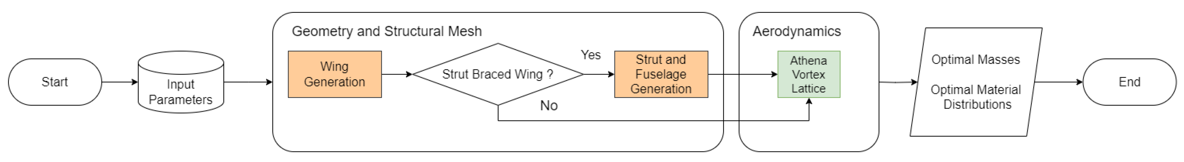
The methodology used to generate the SBW finite element model is displayed in Figure 1. It allows for the creation of configurations based on geometrical input parameters, with aerodynamic loads calculated for specified load cases using Athena Vortex Lattice [14], enabling precise estimation of weight and material distribution for various configurations. Each part of the SBW is generated independently and assembled afterwards in a step where the aerodynamic loads are introduced into the structural model. The optimisation problem, including objective function, design variables and constraints, is defined in the end depending on the load cases considered. In these cases, the objective is to minimise the overall mass of the wing, with particular interest in the optimal material distribution along the wing, which is expected to differ from a conventional configuration. The SBW configuration considered is based on the European project INDIGO, investigating large aspect ratio wings designed for short-to-mid range segments such as the A320 one. The project also aims at integrating distributed electric propulsion and advanced techniques for reducing noise and emissions in an SBW configuration.
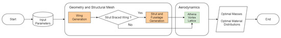
Figure 1.
Code Flowchart.
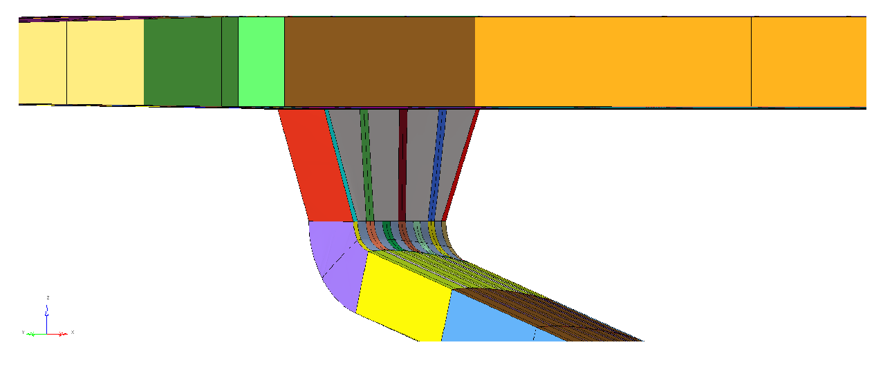
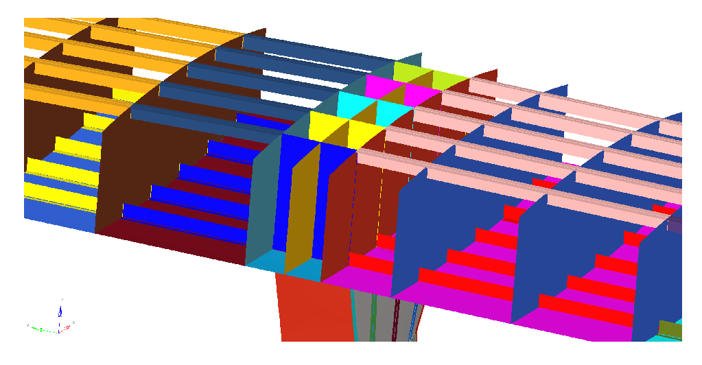
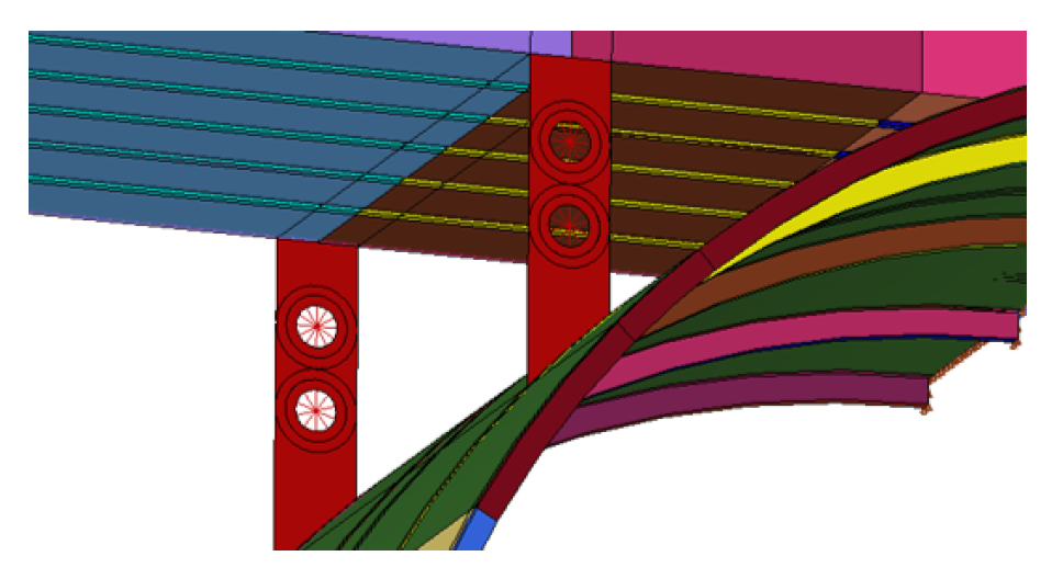
An isometric view of a SBW is shown in Figure 2, where the weight penalty induced by the SBW joint to the fuselage is considered by simulating the fuselage section containing both the wing and strut attachments. The link between wing and strut (Figure 3) was designed to provide a smooth transition between the strut shape at its tip and the lower surface of the wing, incorporating a wing box-like structure. Additionally, two extra ribs and three extra spars were introduced in the section of the wing where the junction occurs to efficiently distribute the forces exerted by the strut, thereby reducing stress concentration and overall weight (see Figure 3 and Figure 4). The high-wing configuration (Figure 5) requires a specific wing-to-fuselage connection. The central wing box at the root is supported by the fuselage frames and reinforced by a lug system typical of high-wing aircraft such as the ATR 42. These lugs connect the front and rear fuselage frames to the corresponding wing spars, transferring the majority of the wing shear force. The fuselage is derived from the A320 and modified to accommodate the strut attachment with minimal disruption of the original airframe (Figure 6). The suggested design aims at integrating a continuous strut on the lower deck, below the cargo floor, using a wing-box-like structure connected to the adjacent fuselage frames to guarantee a lightweight solution while maintaining the aircraft payload capacity.
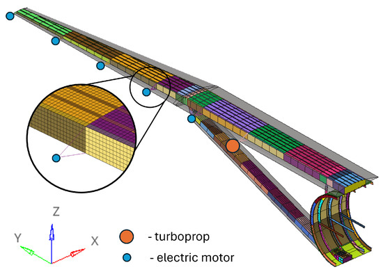
Figure 2.
GFEM—SBW, where each colour represents a different sizing section.

Figure 3.
Wing-to-strut connection.

Figure 4.
Wing-to-strut connection: detailed view of the wing.

Figure 5.
Connection between fuselage and wing.
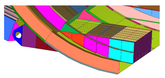
Figure 6.
Strut and fuselage connection.
The wing planform shape considered is displayed in grey in Figure 2. As it may be observed, the leading edge is straight and the trailing edge is tapered starting from 50% of the wing semi-span. The parameters used to describe the wing shape are the aspect ratio (ranging from 15 to 25), taper ratio (0.22 to 0.42), thickness-to-chord ratio at the wing root (12% to 18%) and wing tip (9% to 14%) and the wing projected area (97.92 to 148.88 m2). The thickness-to-chord ratio is assumed constant in the region between the root and half semi-span and equal to the root value. In the outboard region, beyond the half semi-span, it linearly varies between the root and tip values. The airfoil considered is the NASA/Langley LS(1)-0413 (GA(W)-2) general aviation airfoil, whose thickness-to-chord ratio is modified to match the desired input values. The distributed hybrid/electric propulsion system includes one turboprop located at 30% of the semi-span, along with five electric motors evenly spaced to the wing tip (Figure 2). The wing internal structures consists of front and rear spars, placed at 20% and 70% of the local chord, respectively. Distinct material properties are assigned to the spar webs and caps. Ribs are positioned perpendicular to the leading edge, with spacing consistent with the A320 wing. Nevertheless, this arrangement has been adapted to include a rib at each spanwise location where a turboprop or an electric motor is mounted, simulating the pylon connection to the wing and promoting efficient load distribution along the wingbox. The strut features a rectangular planform with constant chord and employs a NACA0024 airfoil profile, preserving a uniform thickness-to-chord ratio across its span. The only defined parameter for the strut is its chord length (ranging from 0.906 to 1.597 m). Other parameters, such as the strut aspect ratio or planform area, are adjusted automatically when the wing geometry is modified. Moreover, the strut/wing attachment is fixed at half of the semi-span.
2. Structural Sizing
2.1. Beam Model
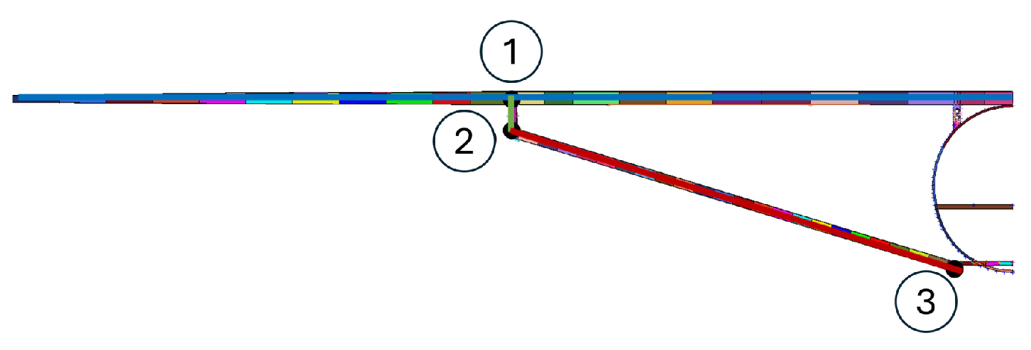
A common conceptual/preliminary design approach is to use low-fidelity models to assess the feasibility of possible design solutions while minimising computational costs. As a result, the initial version of the structural model of Indigo SBW was generated using a beam model, whose wing and strut structure was simplified using 1D finite elements. The lift forces were approximated using the Diederich method [15] and were applied to both wing and strut. The SBW cross sectional thicknesses were optimised to minimise mass, using stresses constraints in each element to meet the von Mises criteria, while simultaneously avoiding buckling. To fully take advantage of the potential of this configuration, a study considering the placement of hinges between the different components was conducted. More precisely, the introduction of hinges in the junction wing-strut connection (1), strut-connector-strut (2) and strut-fuselage (3) was considered, as shown in Figure 7. Various hinge combinations were evaluated to minimise the mass of the SBW. The lowest mass was achieved with a hinge placed at position 3, located between the strut and fuselage. This configuration was considered to develop a higher-order model consisting of a shell-based GFEM.

Figure 7.
Beam model with hinges positions: 1—between wing and strut connection; 2—between strut connection and strut; 3—between strut and fuselage.
2.2. Global Finite Element Model
A parametric global finite element model (GFEM) is automatically created for each wing aerodynamic configuration using a Tool Command Language (TCL) script to generate a wing box model in Hypermesh, following the format of Optistruct. The model includes the wing box components of wing and strut, as well as the fuselage section containing the wing joints, simulated using shell elements (CQUAD4 and CTRIA3). The cantilever wing is meshed by a structured mesh of 64,775 shell elements with 101,032 degrees of freedom, while the SBW model consists of 106,668 total shell elements with a total of 233,066 degrees of freedom.
Stringers are also modelled using shell elements to allow the definition of composites in Hypermesh. They have a T-shaped cross-section and are spaced 250 mm apart from each other. All engines/motors are represented as concentrated masses connected to the respective ribs using connector elements (RBE3) (Figure 2). The GFEM allows for the analysis of two distinct material configurations: one where all components are made of aluminium, and another where composite materials are used for all components, except ribs, lugs and frames, which are invariably made of aluminium. The materials considered are Aluminium 7010-T651 ( GPa, GPa, and Kg/m3) for metal parts and a unidirectional carbon fibre lamina for composite components. The ply properties are GPa, GPa, , GPa, = 1.55 Kg/m3. The considered composite balanced and symmetric layups are modelled as equivalent homogenised anisotropic materials described by their thickness. The ply share percentage for the orientations [0°/±45°/90°] is constrained and kept constant for each component, where the 10% design rule is met to protect against secondary or unpredictable load paths.
A pull up manoeuvrer with a load factor +2.5 g and a push-down one with nz = −1.0 g are the considered as limit load cases with associated 3.75 g and −1.5 g ultimate load conditions. Aerodynamic loads are computed using AVL [14], while the propulsion loads include both thrust and engine/motors inertial loads. Composite laminate strength constraints are defined in terms of the first ply failure maximum strain criterion, including barely visible damage no growth capability, i.e., 3500 in both tension and compression. Since strain limits are defined at the ply level and the plies are not explicitly modelled when homogenised materials are used, the maximum strain constraint is applied to the major and minor principal strains of each shell element rather than directly in the fibre direction. For aluminium, a non-yielding condition is imposed as the maximum von Mises stress constraint under 70% of the yield stress, equivalent to 289.58 MPa, to account for damage tolerance allowable reduction. This condition is verified for both the top and bottom surfaces of each shell element in the metal components. Stability constraints are enforced as well in terms of buckling avoidance up to ultimate loads, imposing a lower bound of 1.5 on all the eigenvalues calculated in the two limit load cases.
Boundary conditions are defined using the reference frame shown in Figure 2 and Figure 8. For the cantilever wing, symmetry boundary conditions are applied to its plane of symmetry. Additionally, the wing is modelled as a high-wing configuration with lugs positioned on the front and rear spars. The displacement of the front lug is constrained in the x- and z-directions, while the displacement of the rear lug is constrained only in the z-direction. For the strut-braced wing, symmetry boundary conditions are also applied to the fuselage wing and strut symmetry plane. Additionally, the upper lugs at the connection between the wing and fuselage (Figure 5 and Figure 8) allow rotation along the x-axis, while the lugs connecting the fuselage wing box to the strut (Figure 6 and Figure 8) allow multidirectional rotation, distributing the loads as spherical joints. Furthermore, two RBE3 elements are defined on the -plane of the front and rear frames, connecting all nodes of the fuselage within each plane (Figure 8). For the front frame, the displacements of the connected nodes are constrained in the x- and z-directions, while for the rear frame, the displacements are constrained only in the z-direction.
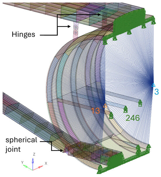
Figure 8.
GFEM—SBW: detailed boundary conditions.
The optimisation design variables are defined by dividing each lifting surface component into spanwise sections, assigning a different design variable to each section of each component. This segmentation allows for variations in material thicknesses across components such as skins, stringers, spars and ribs, enabling a detailed analysis of material distribution along the span while ensuring computational efficiency. For the cantilever configuration, the wing is divided into 11 sizing sections resulting in a total of 97 design variables. In the SBW configuration, the wing is divided into 13 sizing sections, while the strut is segmented into 7 sizing sections. The total number of design variables is 390 considering also the fuselage components. When composite components are considered, the ply thickness is varied in a discrete way, using a manufacturing thickness of 0.17 mm to compute the number of laminae per laminate while maintaining the pre-defined ply percentages.
3. Results
The optimal mass of a cantilever wing and SBW, considering a wing with an aspect ratio of 20, a taper ratio of 0.32, a thickness-to-chord ratio of 15% at the wing root and 11.5% at the wing tip and a projected wing area of 122.4 m2, is discussed below. This represents an example of a possible SBW configuration, demonstrating the effectiveness and applicability of the developed framework. Additionally, the framework was previously validated by predicting the weight of the ATR42 wing, confirming its accuracy.
3.1. Cantilever Wing
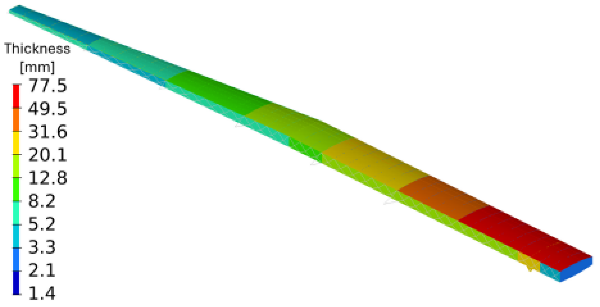
The thickness distribution of the cantilever wing aligns with expectations for both aluminium and composite materials, with thicknesses decreasing progressively from the root to the tip. This distribution is influenced by considerations of both strength and buckling. The increased thickness near the wing root is primarily driven by the significant bending moments of high-aspect-ratio wings, as well as by the need to prevent buckling in the upper skin under positive load factors (Figure 9), which are considered greater in magnitude than negative ones. For the case using aluminium, an optimal semi-wing mass of 5.018 tons was achieved, with the corresponding thickness distribution shown in Figure 10. For the case employing carbon fibre-reinforced polymers Figure 11, an optimal mass of 4.786 tons was obtained, representing a weight reduction of around 5%. These savings could potentially be enhanced further by optimising the stacking sequence, which, as previously mentioned, was pre-defined in this study. Additionally, it is possible that the carbon optimisation converged to a local minimum, as a greater reduction in optimal weight was expected.
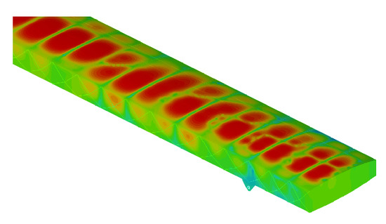
Figure 9.
Cantilever wing buckling: 2.5 g load case.
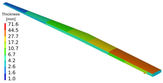
Figure 10.
Cantilever wing: aluminium thickness distribution in mm.
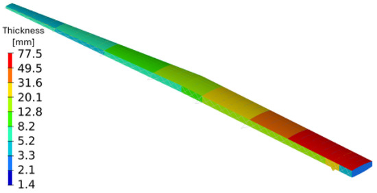
Figure 11.
Cantilever wing: carbon thickness distribution in mm.
3.2. Strut-Braced Wing
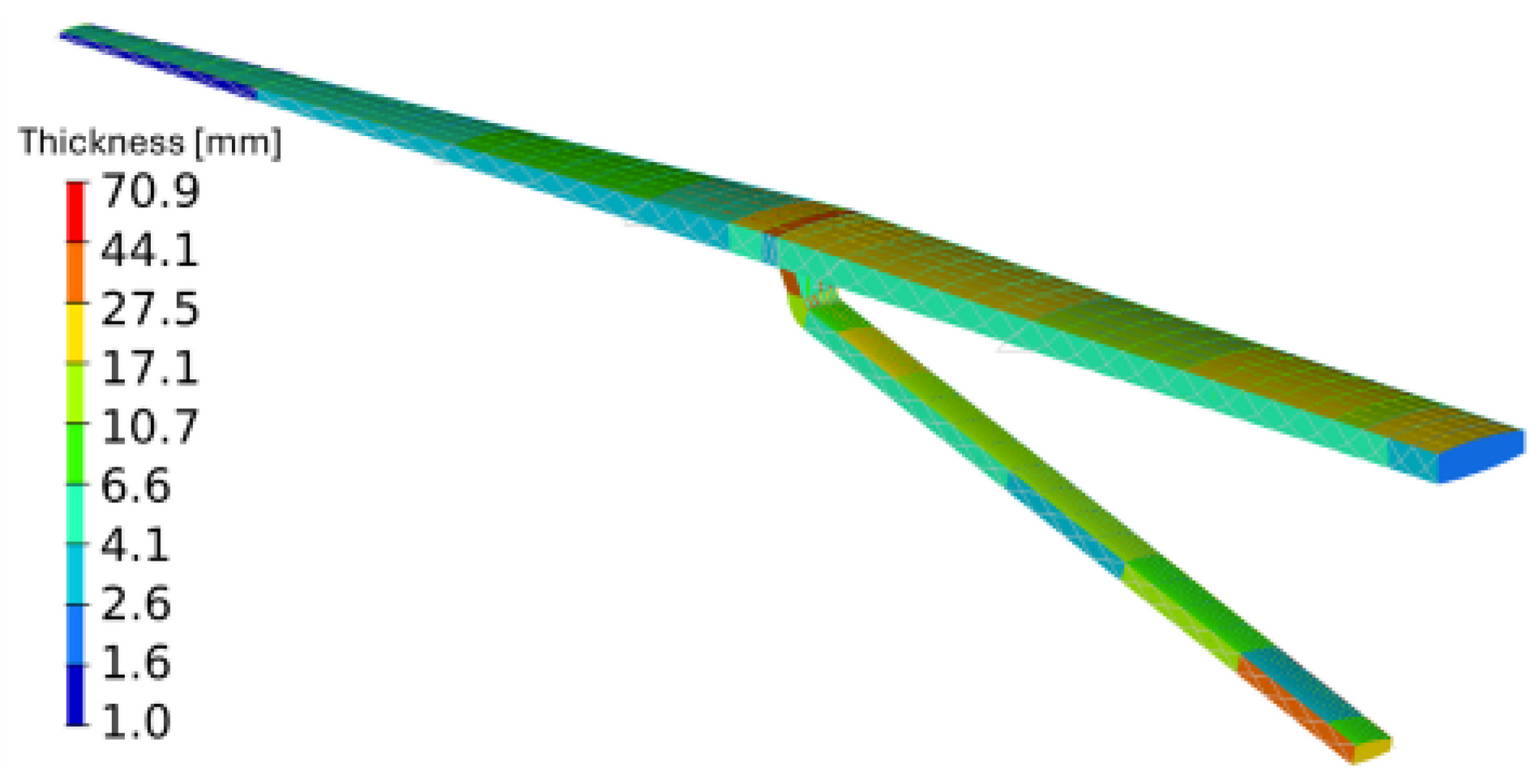
Figure 12 shows the optimal thickness distribution of a fully aluminium SBW resulting in an optimal mass of 4.122 tons for the semi-wing and semi strut. This represents a weight reduction of approximately 15% compared to the aluminium cantilever wing. When composite materials are used, as illustrated in Figure 13, the optimal mass is 2.704 tons. This corresponds to a reduction of about 35% compared to the aluminium SBW configuration and approximately 44% compared to the composite cantilever wing. As with the cantilever wing, the optimal thickness distribution for the SBW is influenced by both strength and buckling constraints. However, the presence of the strut requires a different stiffness and material distribution for optimal load transfer between the wing and strut. Unlike the cantilever wing, where the thickness distributions for aluminium and carbon closely align, this similarity does not hold for the SBW configuration. This divergence may be due to the varying ply percentages in different components of the carbon configuration, resulting in distinct thickness distributions. Additionally, the thickness distribution may correspond to a local minimum, further explaining the differences between the two material configurations.

Figure 12.
SBW: Aluminium thickness distribution in mm.
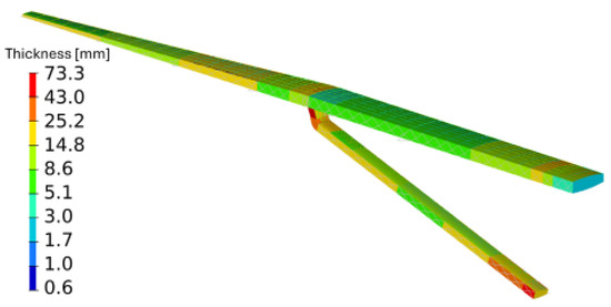
Figure 13.
SBW: Carbon thickness distribution in mm.
A common feature of the thickness distributions for both materials is the significantly increased thickness in critical regions, particularly at the connection between the strut and the wing, as well as the strut and the fuselage joints. This is expected, as these areas handling high concentrated loads are sized by strength requirements. Given that the strut supports the wing during negative load factor loading and reduce its vertical displacement under positive load factors, two additional ribs and three extra spars were added to strengthen the junction to ensuring a more distributed load transfer (see Figure 3 and Figure 4). The other critical area for strength considerations in both material configurations is the connection between the strut and the fuselage lower central wing box. The lifting forces acting on the strut generate shear loads that are transferred to the wing box within the fuselage, leading to a thickness increase in this region. The centre wing box within the fuselage is connected to the adjacent frame webs for shear load transfer. This design choice allows for efficient load distribution, reducing the required thickness of the fuselage skins and minimizing overall weight (Figure 6). Regarding buckling constraints, negative load factor cases are particularly critical, as the strut is subjected to compression, as shown in Figure 14. The strut, however, alleviates the bending moment at the wing root, eliminating the buckling sizing conditions observed in the upper skin of the cantilever wing under positive load factors (Figure 9) where buckling was an active constraint in the optimisation.
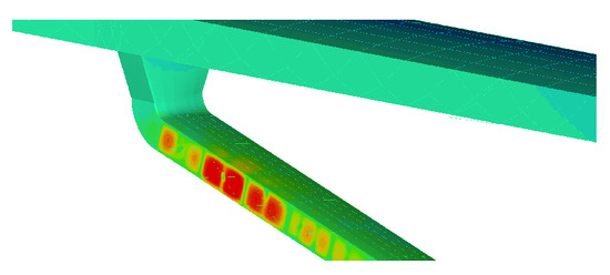
Figure 14.
Strut buckling: –1.0 g load case.
4. Conclusions
This study provides a physics-based model for accurately estimating the mass of a strut-braced wing, in contrast to legacy and empirical methodologies based on experience gathered with traditional configurations. The optimisation results suggest that the strut-braced wing (SBW) configuration can achieve significant weight savings, with a reduction of approximately 44% compared to the composite cantilever wing when composite materials are employed. For cases using only aluminium, the SBW configuration achieved a 15% weight reduction compared to the cantilever wing. Nevertheless, it is worth noticing that the optimisation process employed a gradient-based optimiser, whose outcomes are significantly influenced by the choice of initial points, since the algorithm is susceptible to converging to local minima, particularly in complex design spaces with many design variable and constraints. Despite these limitations, the findings highlight the structural efficiency advantages of the strut-braced wing configuration. While the configuration offers overall weight savings, there are concerns regarding the manufacturability of the connection between the wing and strut. The optimised thicknesses in this region pose challenges for practical manufacturing processes, indicating that a future iteration of the connection design should address these issues. Additionally, further refinements in optimisation strategies or initial condition selection could enhance the reliability and robustness of the results, ensuring both structural efficiency and manufacturability.
Author Contributions
Conceptualisation, J.C. and A.C.; methodology J.C. and A.C.; software, J.C.; formal analysis, J.C. and A.C.; investigation, J.C. and A.C.; resources, J.C. and A.C.; data curation, J.C. and A.C.; writing—original draft preparation, J.C.; writing—review and editing, R.C. and A.C.; visualization, J.C.; supervision, R.C. and A.C.; project administration, R.C. and A.C.; funding acquisition, R.C. and A.C. All authors have read and agreed to the published version of the manuscript.
Funding
The activities described in this paper have been carried out under the project INDIGO (Integration and Digital Demonstration of Low-emission Aircraft Technologies and Airport Operations), coordinated by R. Cavallaro from Universidad Carlos III de Madrid. The INDIGO project (grant agreement No 10109605) has received funding from the European Climate, Infrastructure and Environment Executive Agency (CINEA) under the Horizon Europe programme.
Institutional Review Board Statement
Not applicable.
Informed Consent Statement
Not applicable.
Data Availability Statement
The data presented in this study are available on request from the corresponding author.
Conflicts of Interest
The authors declare no conflicts of interest.
References
- Cavallaro, R.; Demasi, L. Challenges, ideas, and innovations of joined-wing configurations: A concept from the past, an opportunity for the future. Prog. Aerosp. Sci. 2016, 87, 1–93. [Google Scholar]
- Carrier, G.G.; Arnoult, G.; Fabbiane, N.; Schotte, J.-S.; David, C.; Defoort, S.; Benard, E.; Delavenne, M. Multidisciplinary analysis and design of strut-braced wing concept for medium range aircraft. In Proceedings of the AIAA SCITECH 2022 Forum, San Diego, CA, USA, 3–7 January 2022. [Google Scholar]
- Pfenninger, W. Design Considerations of Large Subsonic Long Range Transport Airplanes with Low Drag Boundary Layer Suction; Technical Report; Northrop Aircraft, Inc.: Falls Church, VA, USA, 1954; Report NAI-54-800 (BLC-67). [Google Scholar]
- Smith, P.M.; DeYoung, J.H.; Lovell, W.A.; Price, J.E.; Washburn, G.F. A Study of High-Altitude Manned Research Aircraft Employing Strut-Braced Wings of High-Aspect-Ratio; Technical Report No. 19810011539; National Aeronautics and Space Administration: Washington, DC, USA, 1981. Available online: https://ntrs.nasa.gov/citations/19810011539 (accessed on 25 August 2024).
- Turriziani, R.; Lovell, W.A.; Martin, G.L.; Price, J.E.; Swanson, E.E.; Washburn, G.F. Preliminary Design Characteristics of a Subsonic Business Jet Concept Employing an Aspect Ratio 25 Strut-Braced Wing; Technical Report No. 19810002505; National Aeronautics and Space Administration: Washington, DC, USA, 1980. Available online: https://ntrs.nasa.gov/citations/19810002505 (accessed on 25 August 2024).
- Kulfan, R.M.; Vachal, J.D. Wing Planform Geometry Effects on Large Subsonic Military Transport Airplanes. Final Technical Report March 1976-February 1977; Technical Report; Commercial Airplane Group, Boeing Co.: Seattle, WA, USA, 1978. [Google Scholar]
- Jobe, C.E.; Kulfan, R.M.; Vachal, J.D. Wing Planforms for Large Military Transports. J. Aircr. 1979, 16, 425–432. [Google Scholar] [CrossRef]
- Grasmeyer, J.M.; Naghshineh, A.; Tetrault, P.A.; Grossman, B.; Haftka, R.T.; Kapania, R.K.; Mason, W.H.; Schetz, J.A. Multidisciplinary Design Optimization of a Strut-Braced Wing Aircraft with Tip-Mounted Engines; Technical Report; NASA Langley Research Center: Hampton, VA, USA, 1998; MAD 98-01-01.
- Grasmeyer, J. Multidisciplinary Design Optimization of a transonic strut-braced wing aircraft. In Proceedings of the 37th Aerospace Sciences Meeting and Exhibit. American Institute of Aeronautics and Astronautics, Reno, NV, USA, 11–14 January 1999. [Google Scholar] [CrossRef]
- Delavenne, M.B.; Defoort, E.; David, S.; Fabbiane, C.; Schotte, J.S.; Arnoult, G.; Carrier, G. Multi-fidelity weight analyses for high aspect ratio strut-braced wings preliminary design. IOP Conf. Ser. Mater. Sci. Eng. 2022, 1226, 012009. [Google Scholar] [CrossRef]
- Nam, T.; Chakraborty, I.; Gross, J.R.; Mavris, D.N.; Schetz, J.A.; Kapania, R.K. Multidisciplinary Design Optimization of a Truss Braced Wing Concept. In Proceedings of the 14th AIAA Aviation Technology, Integration, and Operations Conference, AIAA AVIATION Forum, American Institute of Aeronautics and Astronautics. Atlanta, GA, USA, 16–20 June 2014. [Google Scholar] [CrossRef]
- Chakraborty, I.; Gross, J.R.; Nam, T.; Perullo, C.; Mavris, D.N. Analysis of the Effect of Cruise Speed on Fuel Efficiency and Cost for a Truss-Braced Wing Concept. In Proceedings of the 14th AIAA Aviation Technology, Integration, and Operations Conference, AIAA AVIATION Forum, American Institute of Aeronautics and Astronautics. Atlanta, GA, USA, 16–20 June 2014. [Google Scholar] [CrossRef]
- Chakraborty, I.; Nam, T.; Gross, J.R.; Mavris, D.N.; Schetz, J.A.; Kapania, R.K. Comparative Assessment of Strut-Braced and Truss-Braced Wing Configurations Using Multidisciplinary Design Optimization. J. Aircr. 2015, 52, 2009–2020. [Google Scholar] [CrossRef]
- Drela, M.; Youngren, H. Athena Vortex Lattice (AVL). Available online: https://web.mit.edu/drela/Public/web/avl/ (accessed on 3 September 2024).
- Ömer Arslan. Calculating the Wing Lift Distribution with the Diederich Method in Microsoft Excel. HAW Hamburg. Available online: https://dataverse.harvard.edu/dataset.xhtml?persistentId=doi:10.7910/DVN/UK2SIV (accessed on 3 September 2024).


Disclaimer/Publisher’s Note: The statements, opinions and data contained in all publications are solely those of the individual author(s) and contributor(s) and not of MDPI and/or the editor(s). MDPI and/or the editor(s) disclaim responsibility for any injury to people or property resulting from any ideas, methods, instructions or products referred to in the content. |
© 2025 by the authors. Licensee MDPI, Basel, Switzerland. This article is an open access article distributed under the terms and conditions of the Creative Commons Attribution (CC BY) license (https://creativecommons.org/licenses/by/4.0/).