Proceeding Paper

The Idea of a “Loop Fragment” of the Finite Element Force Method in the Loop Resultant Method for Static Structural Analysis †

1
Institute of Civil Engineering, Peter the Great St. Petersburg Polytechnic University, 195251 St. Petersburg, Russia
2
Vietnam Atomic Energy Institute, Ministry of Science and Technology, Hanoi 100000, Vietnam
3
University of Science and Technology, The University of Da Nang (DUT-UD), Danang 50217, Vietnam
*
Author to whom correspondence should be addressed.
Presented at the 2024 10th International Conference on Advanced Engineering and Technology, Incheon, Republic of Korea, 17–19 May 2024.
Mater. Proc. 2024, 18(1), 3; https://doi.org/10.3390/materproc2024018003
Published: 20 August 2024

Abstract

:
In this paper, a novel technique called a “loop fragment” (LF) is developed for structural analysis. A simple method is sufficient for establishing the loop system of framed structures using an original idea, the LF of the loop resultant method, and two conversion rules are necessary to find the structure (or equivalent) flexibility matrix of the rod system. This LF is generated by splitting the given structure into indeterminate basic loops. Instead of the conventional approach of treating the redundant forces in the whole structure, the current approach allows for the calculation to be simplified, thanks to the loop compatibility conditions and by dealing with the primary unknowns for each basic loop. Some numerical examples are considered for the structural frame subjected to temperature loads.

1. Introduction

The force method is commonly used in structural analysis for hand calculations; however, it is very difficult to apply it to complex structures in the conventional approach by solving a system of equations with so many unknowns. The development of matrix algebra and matrix calculus has facilitated the automation of structural analysis methods, including the force method. Algorithms were developed to automate the process of solving the system of equations, eliminating the need for manual calculations and reducing computational difficulties. With the use of optimal algorithms, the automation of the force method enables efficient and accurate analysis of complex structures.
The idea of the finite element model (FEM) was first proposed by Hrennikoff (1941) and is now widely used in commercial software such as SOFiSTiK, SCAD, LIRA, SAP2000, and so on. A short history of the development of the finite element method is given in [1]. Recently, the approximate approach has become the so-called hybrid numerical method that has drawn considerable attention in the scientific community, which makes the numerical approach computationally more efficient in solving challenging problems [2,3,4].
Moreover, the advantages of the force method can be exploited for structural analysis in the finite element force method (FEFM), such as an efficient method for space truss structures with cyclic symmetry [5]; a new structural analysis and optimization algorithm for determining the minimum weight of structures with the truss and beam-type members [6]; the formulation using the energy principles for design, optimization, and nonlinear analysis [7]; and the integrated force method [8,9] for studying the behavior of structures as trusses and frames.
The idea of a “loop fragment” of the loop resultant model (LRM) was proposed by Lalin V.V. [10], and the loop resultant method was conceived on the force method for static analysis of structural systems. The aim of this study is to examine the integration of various types of loops and provide numerical examples of how transformation rules can be applied to structure flexibility matrices.

2. Materials and Methods

Each type of rod with independent force parameters at a free point A is used for the presented approach, as shown in Figure 1.
The equilibrium equations of the system can be expressed as follows:
AT · σ = p,
where A—the matrix of equilibrium equations for structural nodes; AT—the transpose of matrix A; σ—the matrix of resultants; and p—the matrix of specified nodal loads.
The deformation and displacement relations are given.
A · U = e = e0 + ey,
where U—the nodal displacement; eo—the initial deformation; and ey—the elastic deformation.
The flexibility matrix of a rod, denoted by Λ, can be defined using the following physical equations.
ey = Λ · σ.
The solution of the homogeneous equilibrium equations AT · σ = 0 is
σ0 = BT · Φ,
where Φ—the nodal displacement and B—the initial deformation.
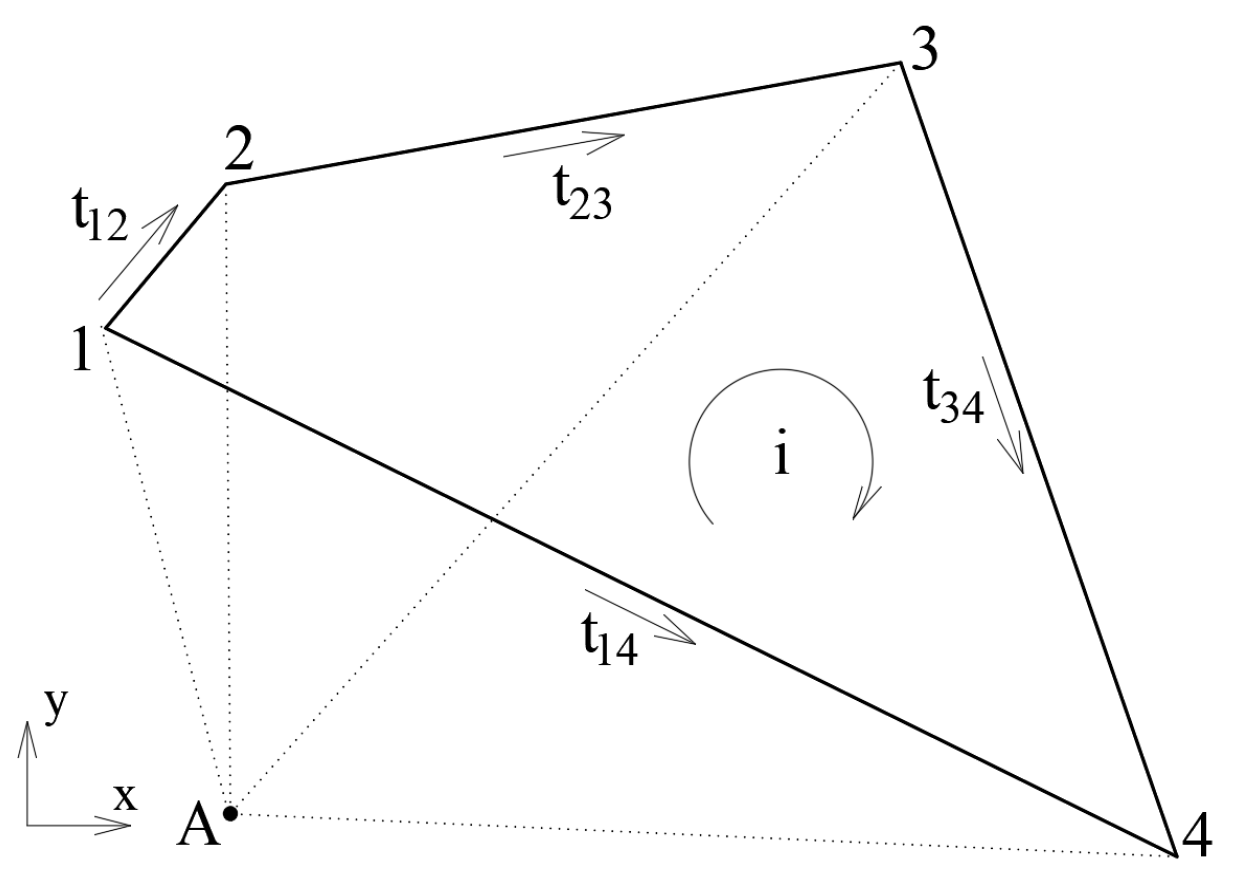
For the basic loop, see Figure 2:
The compatibility equations of deformation for a basic loop with respect to free point A are essential for the loop deformation.
e12 + e23 + e34 − e14 = 0.
Furthermore, it is clear from the homogeneous equilibrium equations that we have
BT · AT = 0 (or A · B = 0),
where matrix B = [I I I I] and I—the unit matrix.
On the other hand, Equation (2) can be multiplied by matrix B and by taking into account Equation (6). This yields the following result:
B · (ey + e0) = 0.
Finally, the resolved system of equations in the force method can be written as follows:
B · Λ · BT · Φ = − B(e0 + Λ · σ),
where B · Λ · BT—the structure flexibility matrix and σ—the particular solution of Equation (1).
In the following, we consider two main rules to be applied for the procedure in building an algorithm.
Rule 1: The sum of the degrees of each statically indeterminate loop should be equal to the total degree of the entire statically indeterminate structure.
Rule 2: Selected loops can have one or several common rods and vice versa, but it is necessary to satisfy the condition of independence of each loop, i.e., an individual rod must appear at least once in the basic loop.
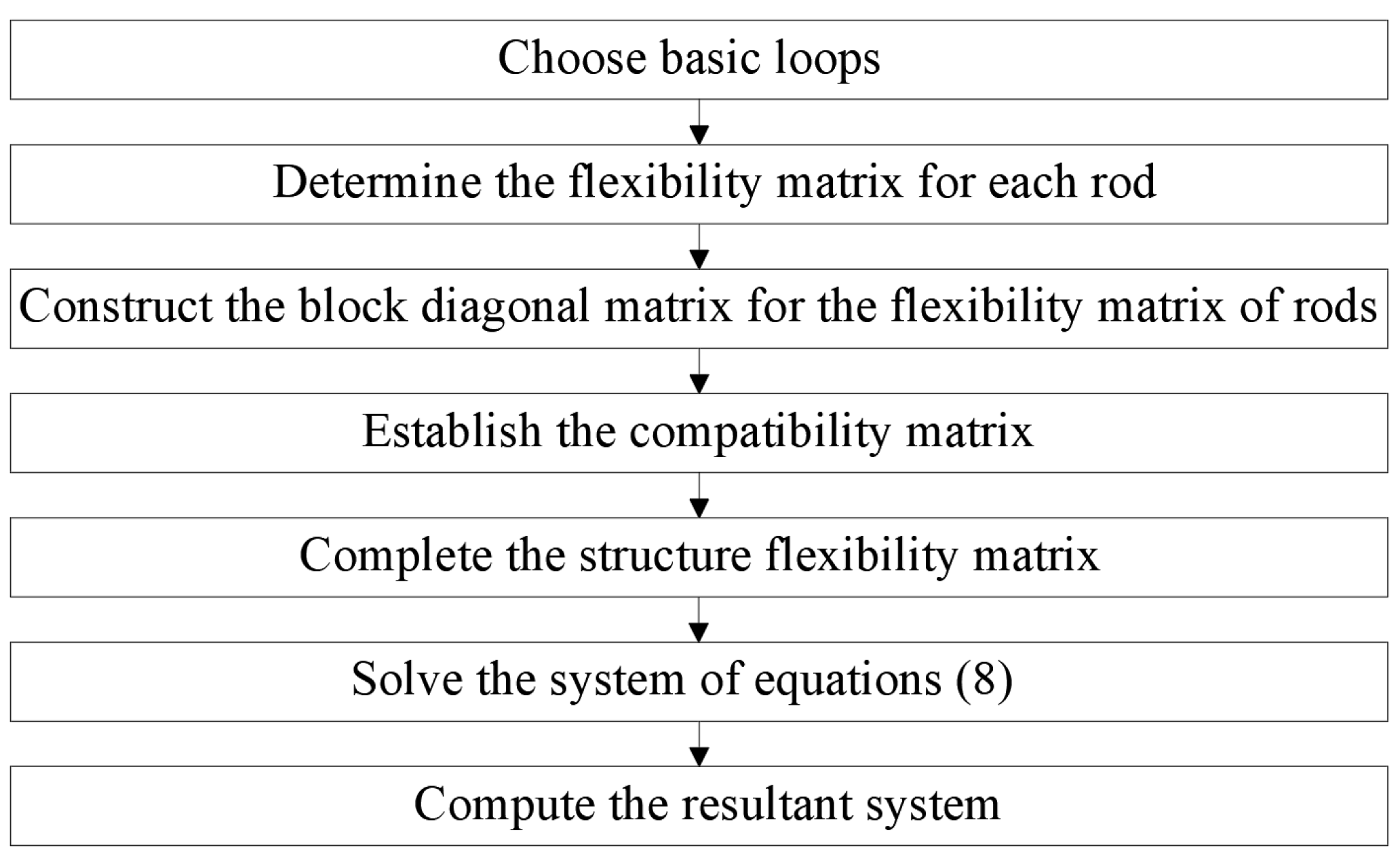
Figure 3 presents a general procedure for the algorithm of the loop resultant method.
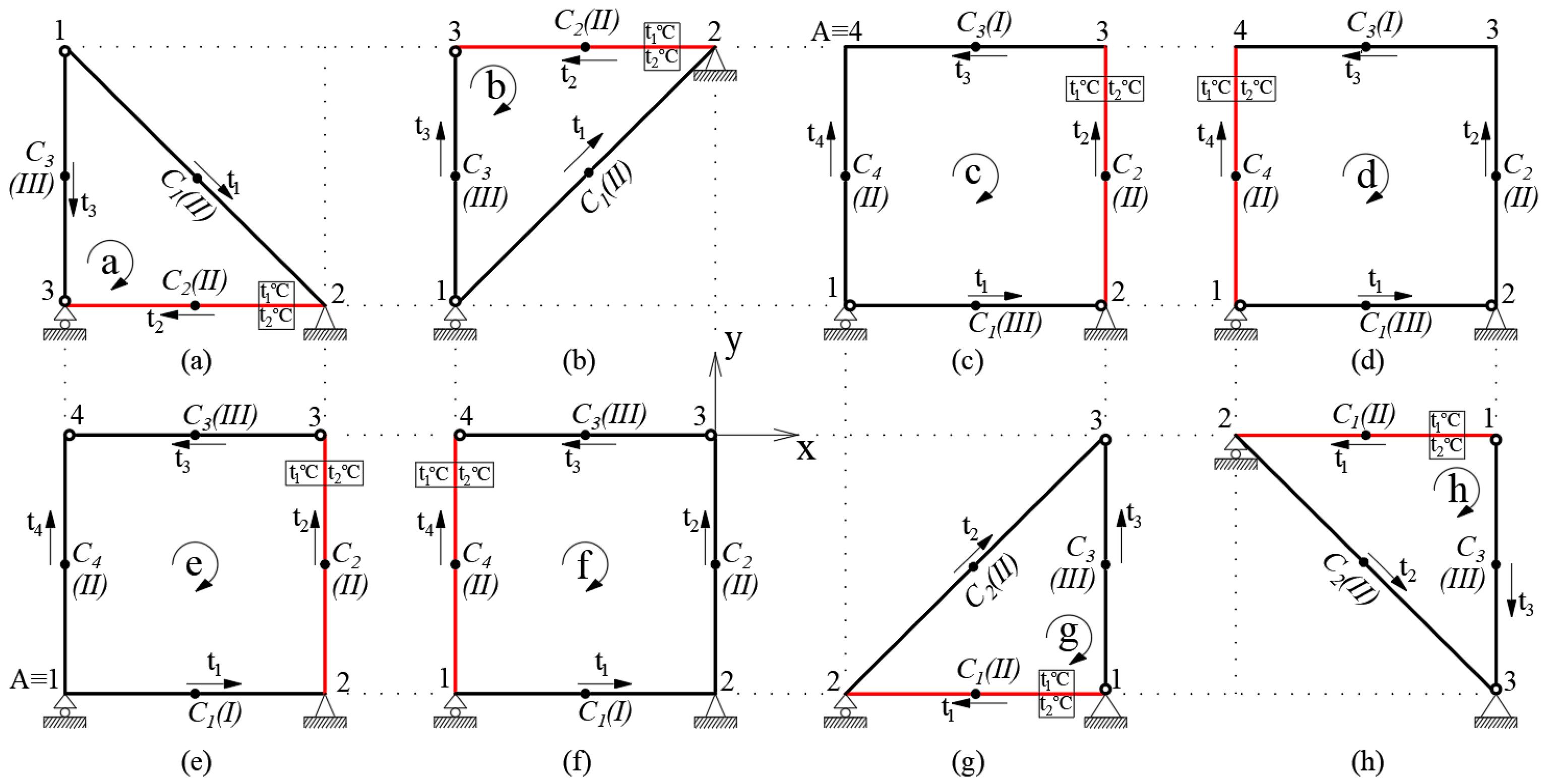
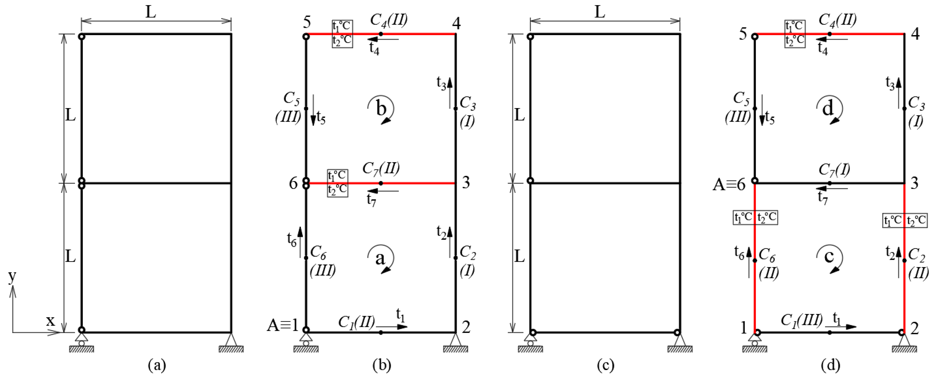
We utilize the algorithm mentioned above to determine the bending moments of framed structures. We then proceed to compare the outcomes of the loop resultant models and finite element models for rod systems under temperature loads. The framed structures are shown in Figure 4, Figure 5, Figure 6, Figure 7 and Figure 8: the length of the rod is L = 2 m; the cross-sectional area is A = 0.04 m2; the Young’s modulus is E = 3 × 10¹⁰ Pa; the moment of inertia of an area is I = 1.33 × 10⁻⁴ m4; the temperature loads are t1 = 15 °C and t2 = 5 °C; and the coefficient of linear thermal expansion is α = 10−5 C−1.
In Figure 4c, an example of the information for loop c is shown as follows: coordinating node A(L/2;3L/2), type I rod (from node 3 to node 4), length L = 2 m, center point C3(L;3L/2), and the projection of a unit vector t3(−1;0). Similarly, the other rods are created as follows: type II (from node 1 to node 4), L = 2 m, C4(L/2;L), t4(0;1); type III (from node 1 to node 2), L = 2 m, C1(L;L/2), t1(1;0); and type II (from node 2 to node 3), L = 2 m, C2(3L/2;L), t2(0;1).
Table 1 and Table 2 show the results of bending moments in basic loops a and c, respectively.

3. Results and Discussion

In this section, the results of the loop resultant model are shown through numerical examples of different ways of combining loops in a framed structure. The framed structure is described as a set of loops extended in two directions along the x and y axes.
For the combination of triangular loops, see Figure 5.
Table 3 shows the results of bending moments in rod systems a and c.
The combination of square loops (see Figure 6).
Table 4 shows the results of bending moments in rod systems a and c.
The use of both triangular and square loops can be seen in Figure 7.
In Table 5, the results of bending moments in rod system a correspond to load cases b, c, and d.
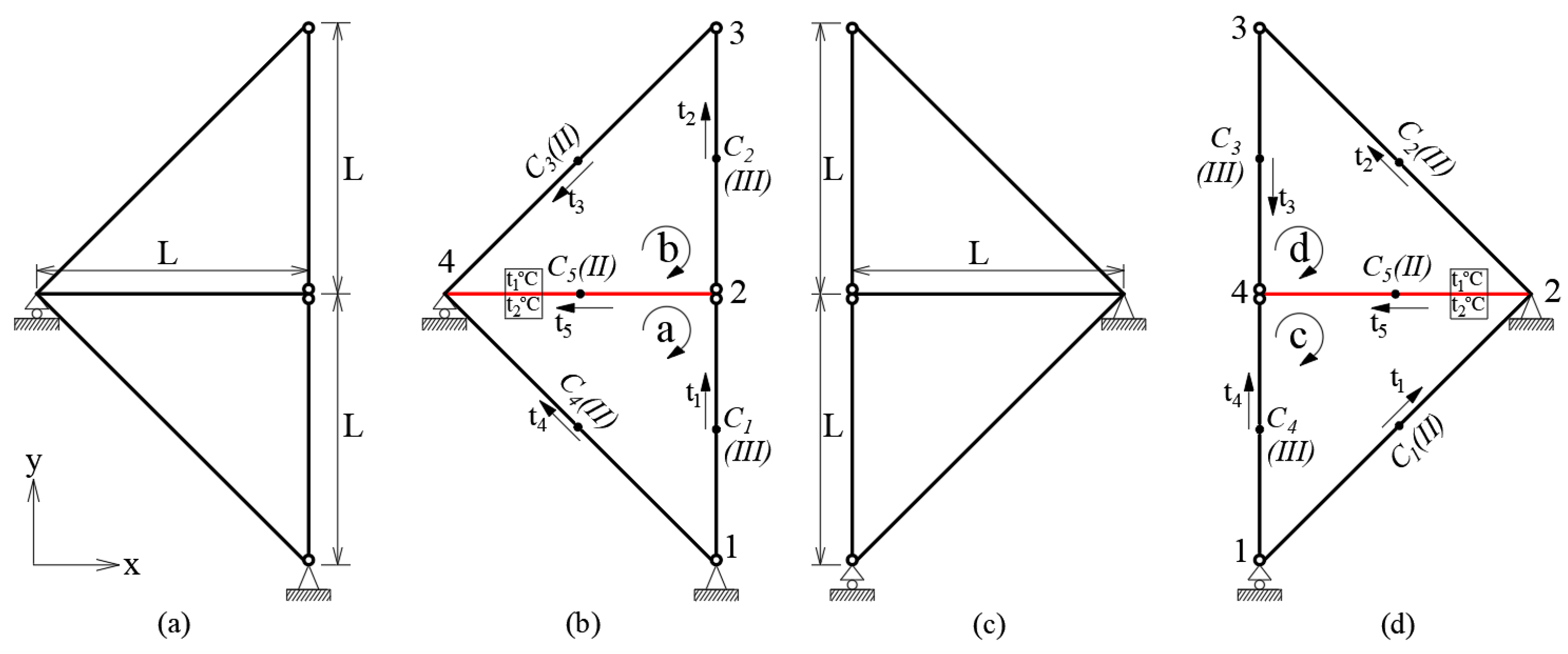
The figure shows the combination of five loops (see Figure 8).
Table 6 displays the bending moment results for rod systems a and b.
Consider the five examples above, which compare the results obtained from the LRM model with those from the FEM model, as shown in Table 1, Table 2, Table 3, Table 4, Table 5 and Table 6. The errors in these comparisons are relatively small. This demonstrates a new approach for structural analysis, where accurate results can be achieved by analyzing the behavior of large rod systems through the analysis of basic loops.

4. Conclusions

The fact that the relative error between the loop resultant model and the finite element model does not exceed 0.9% in the studied examples demonstrates the effectiveness of the loop resultant model in accurately representing the behavior of the structural system. The use of the loop fragment has indeed proven effective in developing the finite element force method for structural analysis.
The application of the classical force method in automation is facilitated by the proposed algorithm, which enhances the efficiency of implementing the force method in automated systems. By integrating this proposed algorithm with automation tools, engineers can achieve significant improvements in analyzing and designing structures.

Author Contributions

Conceptualization, V.V.L.; methodology, V.V.L. and H.H.N.; validation, I.I.L.; formal analysis, A.M.V.; investigation, T.Q.T.L. and T.M.D.L.; resources, I.I.L.; data curation, H.H.N.; writing—original draft preparation, V.V.L.; writing—review and editing, H.H.N.; visualization, I.I.L.; supervision, A.M.V. All authors have read and agreed to the published version of the manuscript.

Funding

This research received no external funding.

Institutional Review Board Statement

Not relevant.

Informed Consent Statement

Not applicable.

Data Availability Statement

All data supporting the reported results have been included in this manuscript.

Conflicts of Interest

The authors declare there are no conflicts of interest.

References

  1. Bi, Z. Finite Lement Analysis Applications, 1st ed.; Elsevier Inc.: Amsterdam, The Netherlands, 2018; pp. 17–20. [Google Scholar]
  2. Lalin, V.V.; Rybakov, V.A.; Ivanov, S.S.; Azarov, A.A. Mixed finite-element method in V.I. Slivker’s semi-shear thin-walled bar theory. Mag. Civ. Eng. 2019, 89, 79–93. [Google Scholar] [CrossRef]
  3. Meleshko, V. Software complexes and new approaches to non-linear analysis of framed structures. SHS Web Conf. 2018, 44, 00061. [Google Scholar] [CrossRef]
  4. Kurochkina, I.V.; Milokhova, V.I.; Mokshanova, R.A.; Voronkova, G.V. Solution of spatial frame structure with large node displacements by finite element method in a mixed form. Int. Res. J. 2017, 61, 45–50. [Google Scholar] [CrossRef]
  5. Koohestani, K. An orthogonal self-stress matrix for efficient analysis of cyclically symmetric space truss structures via force method. Int. J. Solids Struct. 2011, 48, 227–233. [Google Scholar] [CrossRef]
  6. Sedaghati, R.; Esmailzadeh, E. Optimum desing of structures with stress and displacement constraints using the force method. Int. J. Mech. Sci. 2003, 45, 1369–1389. [Google Scholar] [CrossRef]
  7. Kaveh, A.; Rahami, H. Nonlinear analysis and optimal design of structures via force method and genetic algorithm. Comput. Struct. 2006, 84, 770–778. [Google Scholar] [CrossRef]
  8. Patnaik, N.; Coroneos, M.; Hopkins, A. Recent advances in the method of forces: Integrated force method of structural analysis. Adv. Eng. Softw. 1998, 29, 463–474. [Google Scholar] [CrossRef]
  9. Wang, Y.; Senatore, G. Extended Integrated force method for the analysis of prestress-stable statically and kinematically indeterminate structures. Int. J. Solids Struct. 2020, 202, 798–815. [Google Scholar] [CrossRef]
  10. Lalin, V.V.; Ngo, H.H. The loop resultant method for static structural analysis. Int. J. Comput. Civ. Struct. Eng. 2022, 18, 72–81. [Google Scholar] [CrossRef]
Figure 1. The element forces: (a) the first type of rod; (b) the second type of rod; (c) the third type of rod.
Materproc 18 00003 g001
Figure 2. The 4-rod loop.
Materproc 18 00003 g002
Figure 3. A flowchart of the algorithm.
Materproc 18 00003 g003
Figure 4. The planar frames: (a,b,g,h) triangular basic loops; (cf) square basic loops.
Materproc 18 00003 g004
Figure 5. Computational models: (a,c) the frames; (b,d) two triangular loops.
Materproc 18 00003 g005
Figure 6. Computational models: (a,c) the frames; (b,d) two square loops.
Materproc 18 00003 g006
Figure 7. Computational models: (a) the frame; (bd) load cases.
Materproc 18 00003 g007
Figure 8. Computational models: (a) the 15-rod structure; (b) the 14-rod structure.
Materproc 18 00003 g008
Table 1. Comparison of the results of the LRM and FEM (loop a).
LRM (Nm)FEM (Nm)ε (%)
1s0.000.000.00
1e−1242−12340.68
2s124212340.68
2e,3s,3e0.000.000.00
Table 2. Comparison of the results of the LRM and FEM (loop c).
LRM (Nm)FEM (Nm)ε (%)
1s,1e,2s0.000.000.00
2e,3s,3e6005970.41
4s0.000.000.00
4e−600−5970.41
Note: In Table 1 and Table 2, the ordinal numbers 1, 2, 3, and 4 correspond to the rods, while the bending moments at the start and end nodes are represented by s and e. The relative error ε(%) between the LRM and FEM solutions can be calculated using the formula 100 × |LRM − FEM|/|FEM|.
Table 3. Comparison of the results of the LRM and FEM.
System aSystem c
LRM (Nm)FEM (Nm)ε (%)LRM (Nm)FEM (Nm)ε (%)
1s0.000.000.000.000.000.00
1e,2s0.000.000.00−878.68−872.610.69
2e,3s0.000.000.000.000.000.00
3e,4s−878.68−872.610.690.000.000.00
4e0.000.000.000.000.000.00
5s0.000.000.00+1757.35+1745.210.69
5e+1757.35+1745.210.690.000.000.00
Note: The maximum relative error is 0.69% in Table 3.
Table 4. Comparison of the results of the LRM and FEM.
System aSystem c
LRM (Nm)FEM (Nm)ε (%)LRM (Nm)FEM (Nm)ε (%)
1s0.000.000.000.000.000.00
1e−625.00−622.760.360.000.000.00
2s+625.00+622.760.360.000.000.00
2e+625.00+622.760.36+197.80+196.130.84
3s,3e,4s+125.00+124.960.03+659.34+656.290.46
4e,5s,5e0.000.000.000.000.000.00
6s0.000.000.00−197.80−196.130.84
6e0.000.000.000.000.000.00
7s+500.00+497.790.44−461.53−460.170.29
7e0.000.000.00+197.80+196.130.84
Note: The maximum relative error is 0.84% in Table 4.
Table 5. Comparison of the results of the LRM and FEM.
Case bCase cCase d
LRM
(Nm)
FEM
(Nm)
ε
(%)
LRM
(Nm)
FEM
(Nm)
ε
(%)
LRM
(Nm)
FEM
(Nm)
ε
(%)
1s0.000.000.000.000.000.000.000.000.00
1e−270.97−270.110.32−1083.90−1074.430.87−1354.88−1346.100.65
2s,2e,3s+654.19+651.880.35−383.218−381.7700.38+270.976+270.1100.32
3e,4s,4e,5s,5e0.000.000.000.000.000.000.000.000.00
6s−383.21−381.770.38+1467.12+1457.760.64+1083.90+1075.990.73
6e0.000.000.000.000.000.000.000.000.00
Note: The maximum relative error is 0.87% in Table 5.
Table 6. Comparison of the results of the LRM and FEM.
System aSystem b
LRM (Nm)FEM (Nm)ε (%)LRM (Nm)FEM (Nm)ε (%)
1s0.000.000.000.000.000.00
1e−1242.64−1234.180.68−1354.88−1346.100.65
2s0.000.000.00+270.976+270.1100.32
2e−1242.64−1234.180.68+270.976+270.1100.32
3s0.000.000.000.000.000.00
3e−1242.64−1234.180.680.000.000.00
4s0.000.000.00−270.976−270.1100.32
4e−1242.64−1234.180.68−270.976−270.1100.32
5s0.000.000.00−1354.88−1346.100.65
5e−1242.64−1234.180.680.000.000.00
6s+1242.64+1234.180.680.000.000.00
6e,7s,7e0.000.000.000.000.000.00
8s+1242.64+1234.180.680.000.000.00
8e,9s,9e0.000.000.000.000.000.00
10s+1242.64+1234.180.680.000.000.00
10e0.000.000.000.000.000.00
11s0.000.000.00+1083.90+1074.430.87
11e0.000.000.000.000.000.00
12s+1242.64+1234.180.68+270.976+270.1100.32
12e0.000.000.000.000.000.00
13s0.000.000.00+270.976+270.1100.32
13e0.000.000.000.000.000.00
14s+1242.64+1234.180.68+1083.90+1075.990.73
14e,15s,15e0.000.000.000.000.000.00
Note: The maximum relative error in Table 6 is 0.87%.
Disclaimer/Publisher’s Note: The statements, opinions and data contained in all publications are solely those of the individual author(s) and contributor(s) and not of MDPI and/or the editor(s). MDPI and/or the editor(s) disclaim responsibility for any injury to people or property resulting from any ideas, methods, instructions or products referred to in the content.