Review

Rotating Triboelectric Nanogenerators for Energy Harvesting and Their Applications

Institute of Nanoscience and Nanotechnology (INN), National Centre for Scientific Research “Demokritos”, Patr. Gregoriou E & 27 Neapoleos Str., Aghia Paraskevi, 15310 Athens, Greece
*
Authors to whom correspondence should be addressed.
Nanoenergy Adv. 2023, 3(3), 170-219; https://doi.org/10.3390/nanoenergyadv3030010
Submission received: 24 April 2023 / Revised: 20 June 2023 / Accepted: 27 June 2023 / Published: 5 July 2023
(This article belongs to the Special Issue Fabrication and Characterization of Materials for Nanoenergy)

Abstract

:
Addressing the increasing development of IoT networks and the associated energy requirements, rotating triboelectric nanogenerators (R-TENGs) are proving to be strong candidates in the field of energy harvesting, as well as to that of self-powered devices and autonomous sensors. In this work, we review the theoretical framework surrounding the operating principles and key design parameters of R-TENGs, while also associating them with their output characteristics. Furthermore, we present an overview of the core designs used by the research community in energy harvesting applications, as well as variations of these designs along with explicit solutions for the engineering and optimization of the electrical output of R-TENGs. Last but not least, a comprehensive survey of the potential applications of R-TENGs outside the energy harvesting scope is provided, showcasing the working principles of the various designs and the benefits they confer for each specific scenario.

1. Introduction

Technological advancements over recent years have led to widespread development of the so-called Internet of Things (IoT), a new paradigm of high tech, smart everyday life where various devices communicate with each other for sensing and control purposes [1]. As the range of applications for IoT networks flourishes, the need for long lasting, autonomous systems with little or no maintenance requirements has become apparent. This is especially true for applications where the devices are to operate in harsh or inaccessible environments, with limited accessibility for human intervention.
A limiting factor for these applications is the availability of energy sources that can power the individual components of IoT architectures under the intended operating conditions. Batteries, for example, apart from the requirement for frequent interventions in order to be replaced, also raise the question of sustainability and environmental impact [2]. Sustainability and energy autonomy, in particular, are becoming increasingly relevant due to the global energy crisis, which has become even more prominent during recent years [3]. To address the problem, many researchers have turned their focus to harvesting energy from renewable energy sources, developing energy harvesters that exploit forms of energy that are freely available in the environment. These sources can be anything from electromagnetic radiation [4,5], temperature gradients [6,7,8], mechanical stresses [9,10,11,12,13], acoustic waves [14,15,16], and so on.
The transformation of ambient mechanical energy to electrical has been a topic of great interest, with researchers trying to develop methods to harvest this ubiquitous form of energy, which often remains unexploited. In 2012, Wang et al. invented the triboelectric generator by coupling the triboelectric phenomenon with electric induction, thus creating an energy harvester that can transform mechanical energy to electrical [17]. Since then, the triboelectric phenomenon and triboelectric nanogenerators (TENGs), in particular, have gained increasing attention due to their low manufacturing cost, the wide availability of suitable materials, the different options of operating modes, and their high efficiency.
To date, different types of TENGs have been reported as either energy harvesters, sensing devices, or a combination of both. The range of their applications becomes wider as research progresses and TENGs appear to be able to exploit almost every kind of ambient mechanical energy. Lately, there has been growing interest in TENGS that exploit mechanical energy derived from rotational motion, as these types of TENGs can find applications in vehicles, in the conversion of human body motion to electrical energy, in wind and water turbines, etc. Some of the problems researchers face in this area are inherent in TENGs, such as their high internal impedance, which results in a low current output. Others stem from the specificity of rotating parts and the requirement for continuous sliding motion of the TENG materials, which leads to material degradation over time, reduced lifespan of the devices, and, thus, limited system autonomy.
In this review article, we first explore the theoretical framework formulated by various research groups regarding the operating principles of rotating triboelectric nanogenerators (R-TENGs), their design parameters, and the effect they have on their output characteristics. Furthermore, we focus on the different designs that have been proposed to date for the development of R-TENGs as energy harvesters, transforming mechanical energy from a wide range of source to electrical, showcasing the various types of R-TENGs as well as the strategies adopted in order to enhance their electrical output. Last but not least, we highlight different applications of R-TENGs that deviate from the strict definition of energy harvesting, emphasizing their versatility and suitability across a broad spectrum of applications.

2. Theoretical Framework

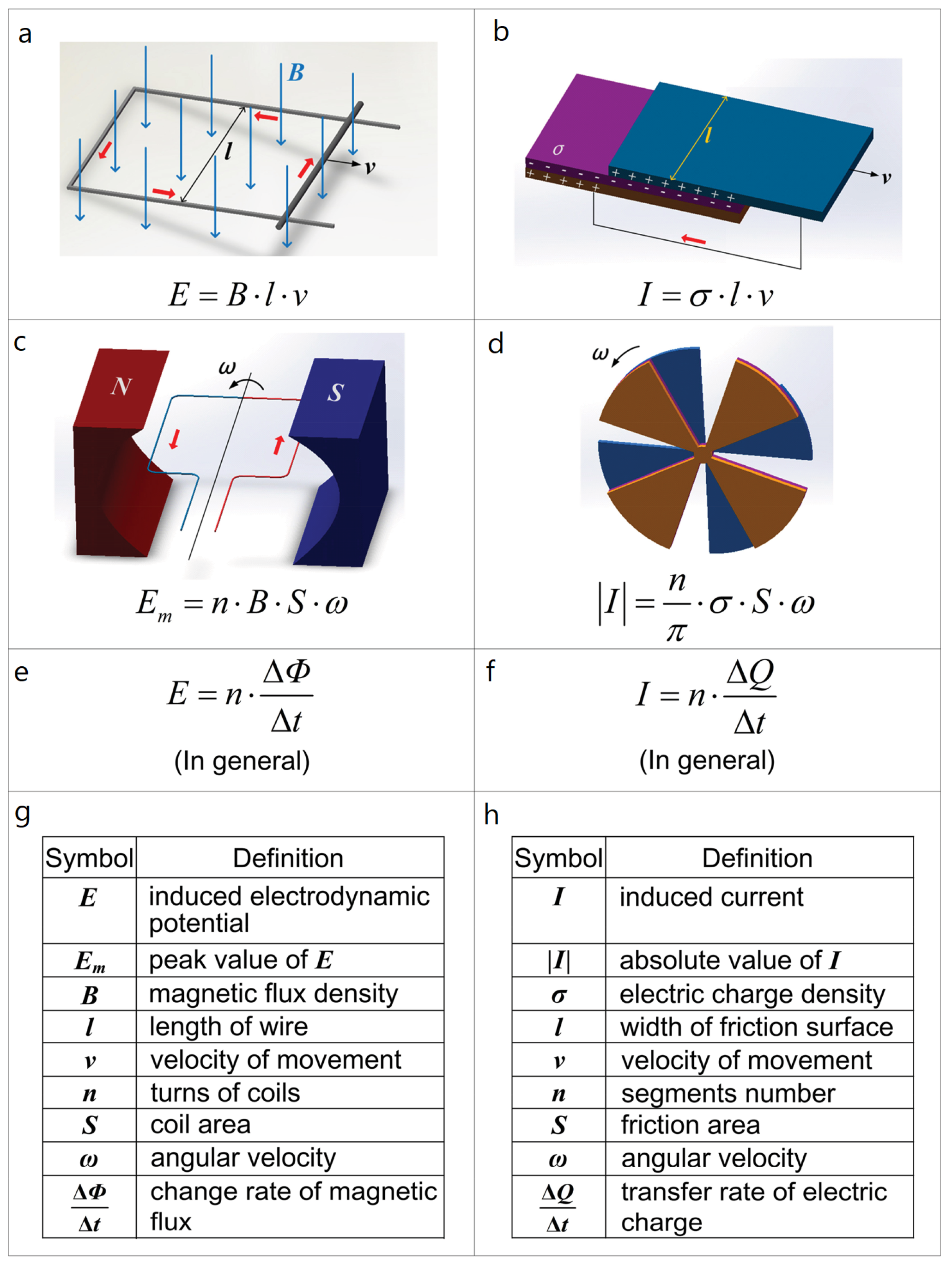
2.1. Operating Principles of (Rotary) TENGs

In order to describe the mechanisms governing the conversion of mechanical energy to electricity has to start from the four fundamental Maxwell equations that unify electromagnetism:
· D = ρ f ,
· B = 0 ,
× E = B t ,
× H = J f + D t ,
where E is the electric field, B is the magnetic flux density, D is the displacement field, H is the magnetic field strength, ρf is the free electric charge density, and Jf is the free electric current density.
The second term in Equation (4) is Maxwell’s displacement current:
J D = D t = ε 0 E t + P t ,
where P is the polarization field and ε0 is the vacuum permittivity. It was introduced by Maxwell for consistency between Ampère’s law and the continuity of electric charges. While Jf refers to the current due to free moving charges, also named conduction current, JD is a time-dependent electric field within a vacuum or a medium due to changing electric flux.
For the case of TENGs, if we consider the basic design in which two dielectrics with back-electrodes are brought to contact and then subsequently separated, electrostatic charges build up on the surfaces of the two dielectric materials, due to contact electrification. These charges are immobile and lead to a surface charge density on the two materials, up to the point of saturation. It can then be demonstrated that the corresponding displacement current density is proportional to the charge density of the two dielectrics and the speed at which the contact-separation cycle is performed. The electrostatic field that is generated in this way drives the free electrons to flow through the external load in order to reverse the effect of surface charge build up, leading to an accumulation of free electrons in the electrode. This already provides us with intuition regarding the output characteristics of TENGs. As it is obvious, the current in the case of TENGs is not based on the free flow of electrons in a conducting material, but instead originates from induction. In other words, contrary to electromagnetic generators where conduction current dominates the energy generation process, the energy harvesting mechanism of triboelectric nanogenerators is dominated by displacement current. This is why in the case of triboelectric nanogenerators the term capacitive conduction is used, as the displacement current is the only conduction mechanism taking place. In particular, the current output of TENGs can be described as follows:
I = d Q d t = C d V d t + V d C d t ,
where the first term describes the current generated by a change in the applied voltage, whereas the second term describes the current generated by a change in the capacitance.
In 2017, Wang expanded Maxwell’s equations by adding what has come to be known as the Wang term, PS [18]. The Wang term is used to describe the presence of strain induced electric charges that are not a result of polarization due to the electric field, but rather occur due to polarization owed to mechanical triggering. By adding the Wang term, the displacement field and the displacement current density are as follows:
D = ε 0 E + P + P S
J D = D t = ε 0 E t + P t + P S t = ε E t + P t + P S t ,
where ε is the permittivity of the medium and ε ε 0 1 + χ ε , where χε represents the electrical susceptibility of the medium.
Over the last years, expanded Maxwell equations have served as a starting point for the development of different models that are used to describe the working principles of TENGs, as well as to facilitate the modeling and optimization of their output. One such example is the quasi-electrostatic model, which is capable of providing a time-dependent solution over the entirety of the geometry under discussion, as wells as the distance-dependent electric field (DDEF) model, which is a special case of the quasi-electrostatic model, exploring the variation of the solutions in one particular direction [19]. Other types of models have also been established utilizing lumped parameters or dimensional analysis in order to provide insights on the physics of the TENGs operation and output, by simplifying the physics of the problem.
The capacitive model, for example, treats TENGs as a voltage source with inherent capacitance. The nanogenerator is described using lumped parameter circuit theory, and two different types of capacitance are taken into consideration: the time-independent capacitance due to the dielectrics and any additional capacitance connected in series with the dielectrics, and the capacitance of the air gap, which is, as expected, time-dependent. These two types of capacitances are considered in series with each other. One more type of capacitance, connected in parallel to the capacitance of the device, is also taken into consideration in order to account for parasitic capacitance of the TENG, which has been observed to be unavoidable and also comparable to the inherent capacitance of the device.
A different approach is Norton’s equivalent circuit, where the TENG is described as a time-dependent current source in parallel with its internal impedance. Essentially, it can be thought of as a variation of the traditional equivalent circuit described in the capacitive model, where the time-varying capacitor is replaced by a time-varying impedance and the voltage source is replaced by a current source based on the TENGs time-dependent, short-circuit current. This approximation is very helpful for simulations aiming to calculate the effective impedance of the nanogenerator, which allows for an estimation of the matching external load that is required to obtain maximum power output [20].
The above approaches can provide a wealth of information regarding TENG design and operating parameters, and can be applied to different types of TENGs, regardless of their working mode. One such example is the work presented by Guo et al., who used the quasi-electromechanical model to construct a 3D mathematical framework that describes the operating parameters of coaxial cylinders in a lateral sliding motion. By doing this, the group extracted the equations for the electric potential as well as the radial and axial electric fields in cylindrical coordinates, resulting in a concise expression for the potential difference across an external load ZL, as described in Equation (9):
Z L A d σ U d t = Φ 1 R 1 , 0 , z , t Φ 2 R 3 , 0 , z , t ,
where Φ1(R1, 0, z, t) and Φ2(R3, 0, z, t) are the electric potentials of the two electrodes and A is the normal contacting area of the cylinders. By solving this first-order differential equation, the group was able to calculate all of the operating parameters, eventually being able to predict the dynamic output of a TENG. A similar result was obtained for the same TENG design by utilizing the capacitive model [21].

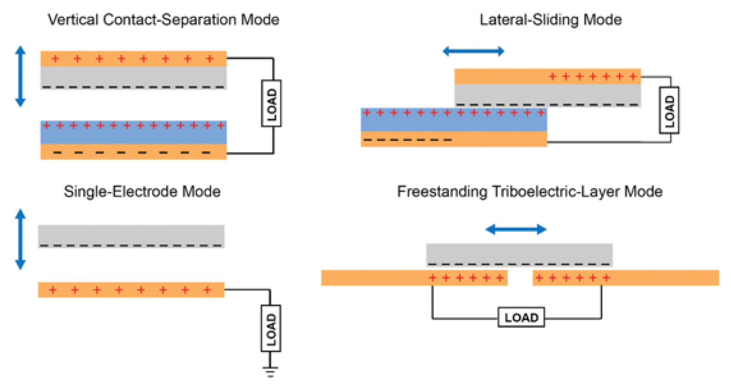
2.2. Classification of TENGs

Based on their mode of operation, TENGs can be classified into one of four types of configuration: (a) contact separation, (b) lateral sliding, (c) single electrode, and (d) free-standing electrode [22]. Contact-separation TENGs consist of a pair of dielectric materials, each with its respective electrode. The surfaces of the two materials are initially brought into contact and are then separated, following reciprocating displacement along the axis normal to their interface. In each cycle, when the two dielectrics are brought to contact, opposite surface charges form on their surface. As the materials are separated, a potential is created between the back electrodes due to induction and when the system is connected to an external circuit, the current flows in order to negate this potential build up. As the materials are brought into contact again, for the second half of the operation cycle, an opposite potential is formed and current flows in the opposite direction. As a result, time-dependent current is generated in each cycle. Similarly, in lateral sliding mode, the displacement happens parallel to the interface. In this case, the formation of opposite surface charges and subsequently the AC output current follows the surface overlap between the two dielectrics. Single electrode TENGs use the surface charges formed between a dielectric and an electrode, using the ground as reference, thus requiring a simpler configuration. These TENGs are operated in a similar manner to contact-separation mode, in that the dielectric and the electrode are brought into contact and then separated by a reciprocating motion along the axis normal to their interface. Finally, free-standing electrode mode could be thought of as a special case of single electrode, in which instead of the ground, a second electrode acts as reference and the output current follows the asymmetrical charge distribution between the two electrodes (Figure 1).

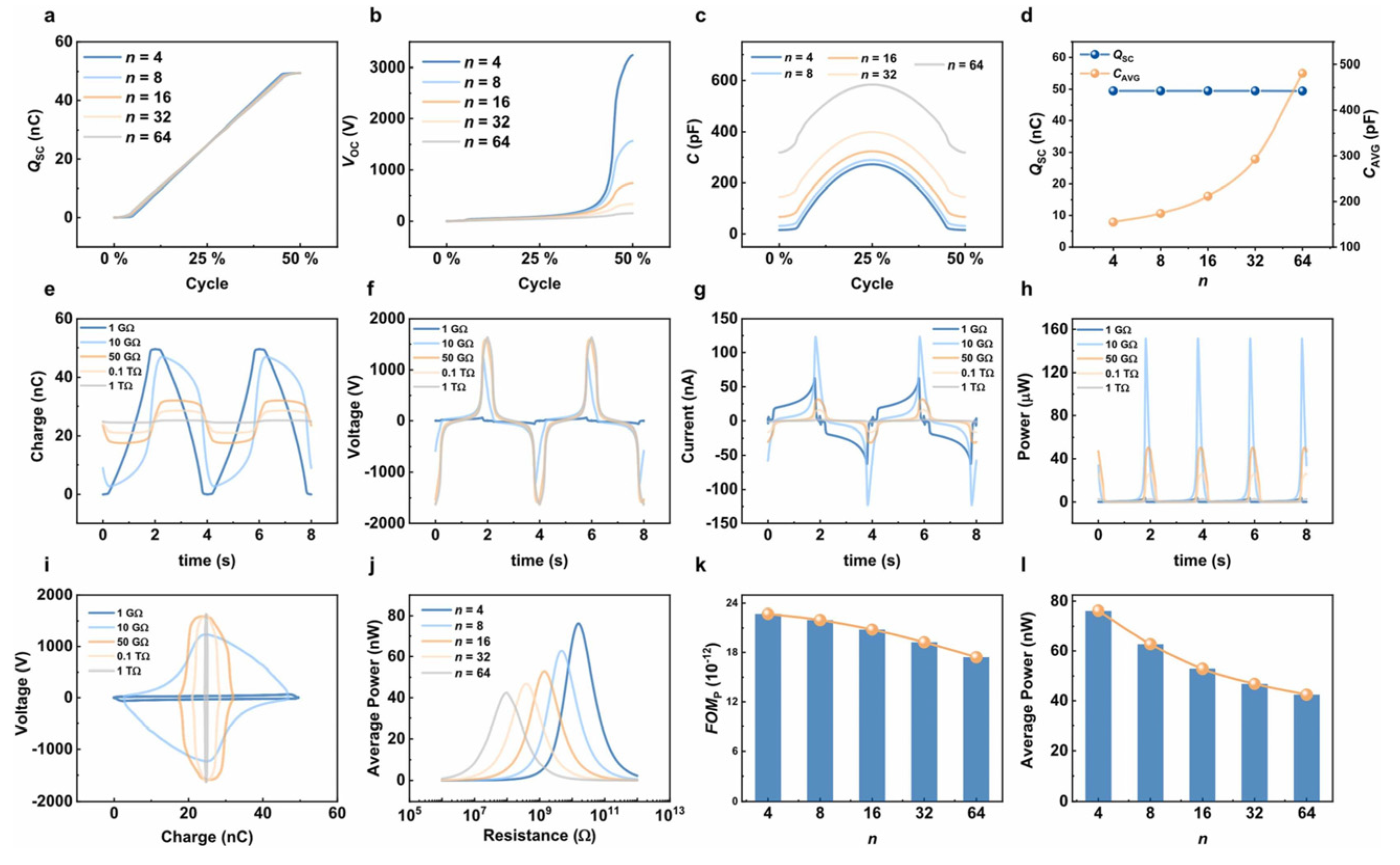
2.3. Design Parameters, Operating Conditions, and Electrical Output

The majority of reported rotary triboelectric generators (R-TENGs) can be categorized under two basic designs, namely disk designs and cylindrical designs, both of which are segregated into a number of gratings. R-TENGs in either category can be further separated with regards to the employed materials into dielectric–dielectric or dielectric–conductor TENGs, whereas the type of contact (or the absence of it) characterizes the mode of operation into contact mode or non-contact mode.
The electrical output of a R-TENG depends strongly on its design parameters, such as the type of materials used, the number of gratings, the size of their surface, the operating mode, the surface spacing (in the case of non-contact mode), and the rotation speed. Understanding the effect of these design parameters on the electrical output characteristics of R-TENGs is crucial for correctly predicting and developing devices suitable for each application. The quantities of interest in R-TENG designs are its capacitance (C), charge density generated by the electrification process (Qsc), open-circuit voltage (Voc), output short-circuit current (Isc), and average maximum power for an arbitrary external load of resistance (Pmax). In 2016, Jiang et al. presented an extensive theoretical study on the rotary sliding disk TENGs, in which they addressed the effect of design parameters on the output of R-TENGs and derived a series of semi-analytical equations that can successfully predict and interpret experimental data [24]. Their work showed that for both cases of dielectric–dielectric and conductor–dielectric, increasing the surface gap leads to a decrease in C, Qsc, and Voc, although the conductor–dielectric displays a higher C and lower Qsc and Voc, while comparatively the charge transfer efficiency is lower in the case of the non-contact mode.
In addition, by studying the effect of the number of gratings, the authors showed the impact of the edge effect, where the ratio between the dielectric length to thickness is small and the assumption of the parallel plates capacitor is no longer valid. This leads to significant deviations from the ideal case, where the semi-analytical equations they proposed can no longer be used to describe the phenomenon and approximations need to be employed. Another important aspect they investigated was that of the external load and its effect on the maximum average power obtained by R-TENG. The group inferred that dielectric–dielectric R-TENGs generate higher Pavg at higher optimum resistance due to smaller capacitance, compared with the conductor–dielectric R-TENGs, while yet another significant observation was that when the rotation speed increased, the output power also increased in a linear way, whereas the matched resistance decreased.
These observations have been verified in more recent years by other research groups such as Khorsand et al. in 2020, who developed an AI-enhanced mathematical model to study the same interdependencies for sliding disk R-TENGs [25]. Of particular interest is the study of Wang et al., which expanded the analysis for cylindrical-type R-TENGs, published in 2021 [26]. In their study, the authors introduced a figure of merit, allowing them to directly compare designs with different effective areas of contact under continuous rotational operation. The effect of the number of gratings, surface distance, and external load on the electrical output characteristics of this type of R-TENG was in agreement with the previous analysis, although the authors suggested that a freestanding conductor–dielectric design demonstrated better tolerance to the effect of surface distance, which allowed for the development of non-contact R-TENGs with increased durability due to lower material wear (Figure 2).
An interesting observation regarding surface distance is that discussed by Deng et al., who observed that in binary layered sliding disk TENGs, the electric field between the two electrodes was found to reach a value of 4.37 MV/m, which was enough to cause air breakdown and inhibit the accumulation of triboelectric charges [27]. As a result, the group proposed that utilizing an additional electrification layer helps reduce the electric field, protecting the device from this inhibiting effect.
Apart from the structural parameters of R-TENGs, external factors have been also found to play an important role in the output characteristics of these devices. Ambient conditions such as temperature and humidity, for example, have been shown to have a significant impact on the voltage output of R-TENGs (Figure 3) [28].
Besides ambient conditions, peripheral electronic components, such as the wires leading out of the R-TENG to the measuring and application system impart parasitic capacitance that, when compared with the capacitance of R-TENG, could greatly affect its output power. Bi et al. studied this effect of parasitic capacitance in relation to the number of segments in a sliding disk R-TENG, showing that for small values of parasitic capacitance, a smaller number of segments resulted in a higher power output, while the reverse was true for high values of parasitic capacitance [29]. In addition, they showed that while the maximum average power decreased with increasing the parasitic capacitance for a given R-TENG, it was proportional to the square of the rotation speed, whereas the voltage amplitude was in proportion to the rotation speed. This means that when the load resistance was smaller than the matched resistance, the effect of parasitic capacitance on the output power of the R-TENG was small, while the output voltage amplitude was completely unaffected.

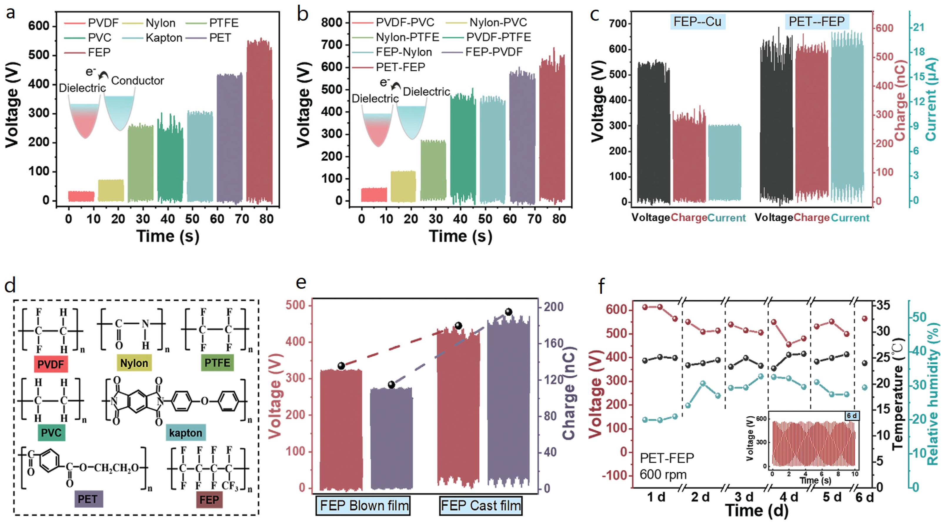
2.4. Enhancing the Electrical Output of R-TENGs

While carefully selecting the design parameters of an R-TENG is an obvious method that can lead to optimized operation and output characteristics, as explained above, research groups have investigated other methods to enhance the conversion of mechanical to electrical energy. Of these methods, two stand out because of both application affinity and sheer performance. Zhang et al. presented a theoretical comparison between triboelectric nanogenerators and electromagnet induction generators (EMIGs), highlighting their equivalency in 2014 [30]. The intuition behind this approach becomes apparent not only when considering that rotating R-TENGS and EMIGs can both be fitted in the same scenarios of energy harvesting applications, but also by comparing the basic characteristics of each type of generator; as the group eloquently highlighted, the output voltage and current of R-TENGs and rotating EMIGs depend on an equal number of physical variables that are similar in nature (Figure 4).
First of all, there are the intrinsic material properties that are of importance for both types of generators, in the form of charge density and magnetic flux density, with a direct impact on the current output of R-TENGs and voltage output of EMIGs. In addition, the structure of the generators comes into play, in the form of the number of segments on a TENG and the number of coil turns for the case of EMIGs. Furthermore, the friction area and the coil area are structural size properties, both of which determine the electrical output of the two types of generators. Last but not least, the angular velocity of the rotator in R-TENGs or the coils in EMIGs is the operating parameter that translates the external mechanical input to be converted in both energy transformation scenarios. Following this comparison, the authors attempt an association between the two types of generators in terms of ideal voltage (EMIGs) and current (R-TENGs) sources, showing that when combining EMIGs and R-TENGs in parallel (R-TENG driven) or serial connection (EMIG driven), the obtained maximum power is approximately two times that of the individual generators for the optimum external load of resistance in the respective configuration. It is of importance to mention that due to the specific characteristics of the two types of generators, EMIGs have a much lower matching impedance (a few Ω) than R-TENGs (in the scale of ΜΩ); however, the measured maximum output power is slightly larger in the case of R-TENGs. In particular, when considering the maximum power per unit volume or per unit mass, R-TENGs displayed significantly larger values because of its compact and lightweight design. This analysis of the equivalency between R-TENGs and EMIGs can provide the basis for the development of hybrid systems that benefit from the merits of both types of generators simultaneously, greatly enhancing the output characteristics of an energy conversion system in various applications. As we will see in the following paragraphs, many research groups have adopted this approach for energy harvesting as well as for sensing applications.
Last but not least, another obvious parameter that can greatly enhance the electrical output characteristics of R-TENGs is that of charge density generated by the polarization of the electrification layers, which is caused by the friction and subsequent charge separation when the materials are brought into contact. As the separation of charges occurs by the friction between two materials, it follows that charge density is gained at the expense of material wear and device stability. To this end, many R-TENG designs have opted for a non-contact mode of operation, where after an initial contact of the materials to induce the separation of charges, a small gap is introduced between the rotator and stator. This gap promotes the longevity of the materials, but as previously discussed, also leads to decreased values in charge generated in the electrification layers. To overcome this drawback, some research groups have proposed a charge pumping strategy [31,32]. The principle of this method involves the integration of a second R-TENG operating simultaneously with the main energy harvester, connected with a voltage-multiplying circuit (VMC), which, in its simplest form, is a rectification bridge with a protective Zener diode, or in more intricate designs it is also comprised of four capacitors. As the two R-TENGs operate, charges from the pumping R-TENG are periodically driven to the electrification layers of the harvesting unit, thus decoupling the charge generation and the interfacial friction processes (Figure 5). This approach has been shown to effectively enhance the density of charges generated on the energy harvesting unit, while simultaneously lowering friction and heat generation, thus also minimizing the requirement of lubrication for the triboelectric surfaces.

3. R-TENGs for Energy Harvesting Applications

Energy harvesting is probably the most obvious field of application for TENGs in general and R-TENGs in particular. As illustrated above, R-TENGs are capable of being lightweight and simple in design, operating in either contact or noncontact mode. The potential of R-TENGs to provide high power density per unit volume and unit mass was illustrated earlier in the theoretical framework, as well. Over the years, many different designs have been proposed, from simple R-TENGs to more sophisticated designs incorporating wireless energy transmission systems, self-excitation modules, or even hybrid ones combining the triboelectric effect with other energy harvesting mechanisms, such as electromagnetism and piezoelectricity.

3.1. Radial Flaps

One of the earliest designs proposed is that of a collection of rotating radial flaps, coming into intermittent contact with other stationary ones. These types of R-TENGs take advantage of soft and flexible materials for the rotor and stiffer materials on the stator to maximize the effective area of contact, leading to an increase in charge separation and electrical output. Such designs can easily incorporate a propeller or a set of wind cups, enabling the harvester to be driven by the wind or the flow of liquids in a system [33,34,35].
In 2013, Xie et al. demonstrated one such design, fabricated from the combination of PTFE, PET, and aluminum [36]. The harvester used wind cups to drive the rotor, on which four PET flaps were situated, with PTFE endings acting as flexible electrification layers. To enhance the generation of triboelectric charges, the group treated the surface of PTFE films with inductively coupled plasma (ICP), creating nanowires and increasing their surface roughness. The triboelectric effect is induced by contact sliding electrification between PTFE and the aluminum stationary electrodes, resulting in single-electrode mode of operation (Figure 6).
The electrical output of the wind energy harvester was tested under different wind velocities ranging from 4 to 7 Bft (v = 0.836 B3/2 m/s), with the maximum output being delivered when operated at 7 Bft. The open-circuit voltage output reached a value of approx. 250 V, leading to a maximum charge difference of 140 nC. The peak current output was measured to be 0.25 mA when the device was connected to a 1 GΩ external load of resistance, while the maximum power output reached 12 mW when driven with an external load of 1 MΩ resistance.
Similar in design was the R-TENG harvester proposed by Rodrigues et al., for use in harvesting mechanical energy from water flow [37]. In this case, the rotating flaps were fabricated using indium tin oxide (ITO) as a flexible substrate, on which aluminum electrodes with PTFE endings were attached, whereas the stationary flaps were made of Nylon 6,6 to act as the second electrification layer. The harvesting unit was fitted with a fan on the bottom end of its shaft, to allow the R-TENG to be driven by water flow (Figure 7).
The group tested different designs containing different numbers of rotating flaps under various water flows, concluding that the best design for maximum electrical output was that of two rotating PTFE flaps and four stationary Nylon 6,6 flaps, for a water flux of 44 L/min. Under these conditions, the measured open-circuit potential reached a value of approx. 102 V with the charge difference and the short circuit current density output reaching 8.1 μC and 120 mA/m2, respectively. The maximum power density output of the harvester was reported to be 6.1 W/m2, allowing the group to light more than 50 serially connected LEDs and charging a 220 μF capacitor to approx. 9 V in a little over 15 min.
In 2018, Du et al. demonstrated an R-TENG harvester that utilizes radial flaps in contact-separation mode for the transformation of wind energy to electricity [38]. The group used the 3D printing technique to fabricate a PLA frame, consisting of a stationary cylinder, on which the TENG was built, and four rotating rollers that are used to induce the contact and separation between the triboelectric layers of the harvester. R-TENG was comprised of a copper electrode layer, on top of which PTFE film patches were placed, acting as electrification layers, the surface of which had been etched using ICP-RIE to enhance its surface roughness. A series of flaps were then placed on top of the PTFE patches, composed of a copper layer, acting as both an electrode and the second electrification layer, and polyimide as the external surface (Figure 8).
The device was tested at a range of rotation velocities, corresponding to wind speeds from approx. 3 to 7 Bft. The maximum electrical outputs of the harvester were determined to be obtained at 120 rpm, under which circumstances the output open-circuit voltage and closed-circuit current were measured to be 280 V and 78 μA, respectively, while the maximum power density output was 2.54 W/m2 when the R-TENG was matched with an external load of 5 MΩ resistance.

3.2. Coaxial Cylinders

A popular design of R-TENGs, especially for applications regarding the transformation of liquid flow to electricity, is the one utilizing cylinders [39,40,41]. In its simplest form, two coaxial cylinders of different radii are fitted one within the other, with the TENG layers sandwiched in the area in between. The devices adopting this conformation can act directly as flow channels, where the fluids in question pass through the triboelectric structure, actuating the rotation of the rotator or even acting as an electrification material, while they are also capable of being fully encapsulated, allowing the harvesters to be directly deployed in harsh environments, without risking deterioration of the materials.
One of the simplest uses of cylindrical geometry in R-TENGs is the one presented in 2014 by Zhang et al. who described a single-electrode R-TENG design that could be applied on bicycle tires in order to harvest mechanical energy from the spinning wheel [42]. The device contains an acrylic disk with PTFE blades that act as the electrification layer and an aluminum foil that is both the second electrification layer and the single electrode. An elastomer base ensures full contact between the electrode and the PTFE blades and the blades were modified by ICP to improve the surface roughness and consequently the charge separation process (Figure 9).
The device was tested at a range of rotation speeds between 100 rpm and 800 rpm, and the group reported a gradual increase in the output voltage, current, and power density with increasing velocity, reaching approx. 0.2 μA and 3.2 mW/m2 at 800 rpm. The electrical output also showed a significant dependence on the symmetricity of the PTFE blades. When two blades were employed in symmetry, the maximum output voltage was measured to be approx. 20 V, which increased considerably when these blades were assembled in non-symmetric positions, to a maximum of 29 V for 800 rpm velocity. By expanding the design to include seven asymmetric PTFE blades, the maximum output voltage was achieved (approx. 55 V), allowing for directly powering 30 commercial LEDs.
In 2013, Bai et al. developed a core–shell structured R-TENG for harvesting air or water flow energy [43]. The inner cylinder of this harvester acted as the rotator and comprised of copper electrodes on top of which PTFE strips were employed as electrification layers, connected in parallel. In order to increase the effective surface area for the charge separation mechanism, PTFE nanoparticles were sprayed on top of the PTFE strips. The outer cylinder, acting as a stator, comprised of copper strips with a dual role, that of both electrodes and second electrification surface (Figure 10a).
The group tested the harvester in a range of rotation velocities and the maximum electrical outputs of the device were obtained when driven at 1000 rpm. Specifically, the maximum open-circuit voltage and short-circuit current density output were measured at 400 V and 90 μA, respectively, while the maximum power density was found to be approx. 37 W/m2.
Another cylindrical R-TENG, this time operating in non-contact sliding mode, was reported by Zhang et al. in 2020 [44]. The group developed a cylindrical, non-contact, and freely rotating TENG to harvest energy from water flow. The harvester consisted of two coaxial, hollow cylinders, with the inner cylinder acting as the stator and the outer one as the rotator. On the outer cylinder, the group placed blades to achieve rotational motion induced by the flow of water and patches of FEP film that had been previously nanostructured via ICP etching, to act as the electrification layer. On the stator, four copper foil patches connected in parallel in pairs act as the electrodes of the TENG (Figure 10b–e).
The device, after the initial contact of the layers in order to induce charge separation, was operated in non-contact mode with a 1 mm gap at 400 rpm. Under these operating parameters, the transferred charges in a single cycle of operation were calculated to be 6.9 nC and the average output voltage and current were 994 V (VOC) and 9 μA (ISC), respectively. The output power of the tribogenerator was evaluated under different external loads of resistance and the maximum power density obtained was 0.33 W/m2 when the device was matched with a 150 MΩ resistance. The group also investigated the effect of rotational frequency on the output electrical characteristics of the TENG, for rotation speeds of 400–2000 rpm. They observed that both variants increased monotonically with increasing the frequency, reaching 1661 V and 12 μA, respectively. After connecting the tribogenerator to a rectification bridge, the device was driven at 2000 rpm and provided a DC current of 16.5 mW/m2, which was able to charge a 10 μF capacitor to a voltage of 65 V within 150 s. The TENG was also tested for its durability by measuring the output voltage after 3 h of continuous operation at 400 rpm. The open-circuit voltage after 3 h was reported to reach an equilibrium value of 598 V (approx. 42% attenuation), showcasing the robustness and long lifetime achieved by the non-contact design.
Feng et al. utilized the coaxial cylinder design to fabricate an oscillating, non-contact R-TENG that was used to harvest low frequency mechanical energy from water wave excitation [45]. R-TENG comprised of a six-bladed rotor with an FEP film on the surfaces of the blades acting as the electrification layer and a cylindrical stator shell on which copper electrodes were attached, acting as both electrodes and the second electrification material (Figure 10f).
The harvester was shown to be able to convert water wave excitation as low as 0.033 Hz with a peak power density of 231.6 mW/m3. The group reported the R-TENG was capable of delivering continuous output power for 85 s following a single excitation, with a maximum open-circuit voltage, generated charge, and short-circuit current output of 120 V, 46 nC, and 1.52 μA, respectively, whereas the maximum generated power was measured to be 159 μW when the R-TENG was matched with a 100 MΩ external resistance load.
A similar concept was showcased in 2022 by Jung et al., who introduced a cylindrical R-TENG that utilizes a set of magnets to induce a swinging motion to the rotator, similar to that of a pendulum [46]. The device is proposed as an energy harvesting solution to transform the mechanical energy of sea waves to electricity. A metallic mass placed on the rotor acts as a pendulum, while two neodymium magnets help to temporarily store potential energy, converting low-frequency input energy to high-frequency electrical output. In addition, a set of rabbit fur strips allow for soft partial contact with the electrification layer, increasing the generated charge (Figure 11).
The group tested their design for different angles of displacement, reporting average power outputs at an optimal load of 0.178 mW, 0.147 mW, and 0.117 mW for 60°, 45°, and 30° angles, respectively. The non-contact mode of operation of this design, in conjunction with the soft partial contact achieved with the fur segments provides considerably enhanced electrical output as well as increased robustness, with the output characteristics of the harvester reported to remain constant after 400,000 cycles of operation.

3.3. Liquid-Solid Contact

Although R-TENGs have often been suggested as a suitable energy harvester to convert the mechanical energy inherent in moving bodies of water (or other liquids), to date, little exploration has been done on the prospect of exploiting the friction generated when a liquid comes into contact with a solid surface [47,48,49].
One such design was proposed by Kim et al. in 2016 [50]. The operating principle of this harvester is based on the flow of water within a tube, using the fluid as an electrification layer. The design includes an acrylic cylinder with a number of patterned aluminum electrodes covered by PTFE to act as the second electrification layer. The cylinder was partially filled with tap water and the electrical output of the TENG was measured for different angular velocities and water volume ratios (Figure 12a).
The device was tested at a range of angular velocities from 50 rpm to 300 rpm, showing increasing voltage and power output as the speed increased, as well for different water volume ratios. When operated at optimum conditions, TENG was found to produce up to approx. 27 V and 3.8 μA and 19.1 μW when coupled with an external load of 20 MΩ resistance, although these numbers can increase with the integration of mutliple triboelectric patches in the tube.
In 2021, Le et al. reported a sophisticated liquid–solid contact electrification R-TENG that was developed so as to not require the use of a rectifier circuit to transform AC output to DC [51]. R-TENG was comprised of a stator with stationary electrical contacts and a rotator with six independent TENG cells. These cell TENGs are in the form of a liquid storage compartment, each with its own lid made of a nanoporous PVDF membrane on copper electrodes. A phase inversion method was employed on commercial PVDF films to change their structure and increase the surface density, enhancing their capability of charge separation as electrification layers. The six TENGs were arranged in radial symmetry and were partially filled with DI water (Figure 12b,c).
The interesting property of this design is the addition of motion-activated switches that are closed when water is in contact with one of two copper electrode surfaces in the cell and open during the transition from one electrode to the other. In this way, a unidirectional current is generated, suitable to be supplied directly to electronic devices without requiring a rectifier circuit. The harvester was tested at 18 rpm and was reported to have a maximum open-circuit voltage, generated charge, and short-circuit current density output of 1.5 V, 2.03 nC, and 11.94 nA/cm2, while the maximum obtained power density was 18.48 nW/cm2 for a matched external load of 20 MΩ resistance.

3.4. Radially Segmented Disk

The radially segmented disk configuration is probably the most popular design for R-TENGs [52,53,54]. One of the first reported R-TENGs of this kind was the one described by Lin et al., who reported a sandwiched structure segmented into four sectors [55]. Structurally, the R-TENG is composed of a PMMA substrate on top of which sits a Kapton® layer with gold electrode on its back side, while the rotator is fabricated by depositing aluminum electrode on a PMMA substrate. The Kapton® layer was processed with ICP in order to increase the effective contact area and enhance the electrical output of the device (Figure 13).
The maximum open-circuit voltage (230 V) and generated charges (40 μC/m2) were obtained at 500 rpm, while the maximum current density output was reported to be 29 mA/m2 when driven at 1000 rpm. The maximum power density output of the harvester was 1 W/m2, when matched with an external load of 10 MΩ resistance.
Another radially segmented disk R-TENG was reported by Zhu et al., comprised of a copper rotator with 60 radially arrayed segments and a stationary disk with radial, interdigitated gold electrodes on top of which a FEP layer is used as an electrification layer. The rotator performs a lateral sliding motion on the upper surface of the FEP thin film inducing opposite charges on the copper IDEs and the FEP layer, due to the triboelectric effect (Figure 14) [56].
The maximum electrical output was obtained at 3000 rpm with a reported Voc, Qsc, and Isc output of 850 V, 0.32 μC, and 3 mA, respectively. Operating their triboelectric harvester under optimum parameters (3000 rpm, 0.8 MΩ), they successfully generated approx. 19 mW/cm2, which is a considerable amount of power, suitable for powering simple electronic devices. Regarding device stability, the group included an adhesion layer and performed plasma treatment of their substrate before metal deposition to ensure increased material adhesion. As reported, their device displayed stable output even after 107 cycles of operation, showing reliable stability.
A different approach was proposed by Zhou et al., of a R-TENG that can be utilized in harvesting mechanical energy from the wheels of a bicycle during cycling and braking modes [57]. The R-TENG consists of a radially segmented steel rotator and a stator comprised of interdigitated copper electrodes with a PTFE layer on top of them acting as the electrification layer. Three brake clamps are also connected to the device, which, when activated, press the stator closer to the rotator, increasing the friction between the PTFE and steel layers (Figure 15).
The R-TENG was tested in two modes at 150 rpm, one non-contact sliding mode with a 0.5 mm gap between the stator and the rotor, representing the riding of the bicycle without braking, and the other in contact sliding mode when the brake clamps are activated. In non-contact mode, the harvester was capable of producing 0.3 mW when matched with a 46 MΩ external load. In contact mode, the electrical output of the device greatly increased; the maximum output open-circuit voltage, generated charge density, and closed-circuit current were measured at 300 V, 24 μC/m2, and 60 μA, respectively, while the maximum output power in braking mode was 2.29 mW when the R-TENG was matched with a 20 MΩ external load of resistance. The robustness of this design was also demonstrated as its electrical characteristics were found to be stable after one million cycles of operation.
The radially segmented disk design has been adopted by many research groups to date, who have developed different R-TENGs using a range of triboelectric materials and structures to address the needs of specific applications. Some researchers have studied designs of the basic architecture, such as the one described by Kuang et al. [58], while others have reported more complex ones, such as the one demonstrated by Yong et al. in 2021 [59], which incorporates more than one R-TENGs in a single design, or the ones proposed by Cao et al. [60] and Li et al. [61], which utilize the Curie effect or the structural response of shape memory alloys to changes in temperature, resulting in devices that transform thermal energy to electrical (Figure 16).
One such design is the R-TENG harvester proposed by Lin et al. in 2020 (Figure 17), which was developed to transform water wave energy to electricity [62]. Lin’s harvester is a freestanding electrode R-TENG that uses a combination of contact electrification and a reciprocal swinging motion, similar to that observed in a pendulum. The TENG is comprised of a stator made of ICP-etched PTFE and copper, and an acrylic rotator with radial segments made of nylon, which functions as the electrification layer. An impeller translates the energy of water waves into a pushing motion, bringing the rotator and the stator into contact with each other and leading to charge transfer between the layers, while a spring restores the gap between the two components. Subsequently, the rotator follows the rotating motion of the shaft, leading to the typical freestanding electrode mode of operation, while an iron mass installed on the rotator leads to an oscillating, pendulum-like motion.
The device was reported to require some time to reach a steady state of charge separation, with the charge at saturation reaching 75 nC. Regarding the electrical output characteristics of TENG, the open circuit voltage was reported to be up to 160 V, depending only on the space charge density of the triboelectric materials, while the short circuit current output was reported to reach approx. 1.5 μA for the maximum trigger acceleration. The device was found to match at 100 ΜΩ external load, producing 74 μW. An interesting property of this design is the slow attenuation of its voltage output with respect to the mechanical trigger, owing to the pendulum-like motion induced by the iron mass on the rotator, which enables the device to convert mechanical input of a very small frequency to electrical energy. In addition, the contactless mode of operation imparts robustness to the generator, with the authors reporting a stable performance after 500,000 working cycles.
Another such variation was presented by Zhang et al., for harvesting energy from the drafts created by rail trains along their path [63]. The basic TENG design comprised of a stator and a rotator, and the group also detailed and advanced device where the rotator was sandwiched between two stators, thus creating two TENGs operating in phase. In this application, the stators were made of copper IDEs, while the rotator consisted of folds made of PTFE and Kapton® on an acrylic disk (Figure 18).
In this design, the polyimide layer adds to the rigidity of the folds and ensures proper mechanical contact, while PTFE acts as the electrification layer. The authors studied different devices using PTFE, PVC, and FEP as electrification layers and tested them for their electrical output in conjunction with their mechanical properties, namely their friction coefficient and durability. Although FEP showed increased current and voltage output compared with PTFE, the latter was preferred by the group for its superior transferred charge versus applied forces. This means that PTFE-based designs required a smaller driving force to operate and consequently suffered less material wear, proving the material ideal for this type of application. Specifically, the single R-TENG design fabricated from PTFE had an output of 160 nA and an open circuit voltage of 126 V when operated at 200 rpm, while maintaining 89.04% of its output after 50,000 cycles of operation. The advanced, double layered design was thus fabricated using PTFE as the electrification layer. This double TENG design was shown to be able to produce a closed-circuit voltage and short-circuit current of up to approx. 1200 V and 0.35 mA, respectively, with the generated charges having been measured to be approx. 2.2 μC. When matched with an optimum external resistance load (1 MΩ), the harvester had an average output power of 47 mW and peak power of 114 mW.
An interesting variation of these types of R-TENGs addresses the lower triboelectric charge that is generated in the case of non-contact mode of operation. While non-contact mode R-TENGs tend to be more robust due to the minimized friction between the materials, they also have a lower electrical output than their contact mode counterparts. To this end, various groups have added small patches of soft materials such as paper or polyester fur, which come into contact with the electrification layer, increasing the generated charges. One example of a such design was presented by Feng et al. (Figure 19a–c), who showed that by adding a paper strip in their design, the R-TENG’s open-circuit voltage and short circuit current output increased from 702 V to 2352 V and from 25 μA to 133 μA, respectively, when operated at 600 rpm, while the generated charges increased from 36 nC to 197 nC. This increase in electrical output was paired with significant robustness of the device, which showed 100% stable output after 1,000,000 cycles [64].
In another example, Li et al. presented a similar concept using polyester fur in their design (Figure 19d–f) [65]. The group tested their design at 900 rpm, reporting a DC voltage output of 15 kV (and an AC voltage output of 10 kV), with the generated charges reaching a value of 516 nC. Regarding the power output of R-TENG, it was found to match with an external load of 110 MΩ, due to the inherent high internal impedance of non-contact TENGs, providing an output of 201.83 mW. To further test their design, the group reported they used the harvester to charge a 5.5 nF capacitor from 0 V to 6.8 kV in just 38 s.
Another approach to increase the amount of generated charges on the triboelectric surfaces of R-TENGs is the one proposed by Long et al. in 2021 [66]. In this design, a rotating, freestanding electrode R-TENG is coupled with a voltage-multiplying circuit (VMC) that can be charged by the rotating TENG and can subsequently induce a fast increase in charge density on the R-TENG itself, greatly enhancing its output. The TENG’s stator consists of 12 radially arranged aluminum electrodes, whose surface is covered with a thin polyamide film. The rotator was fabricated by covering six radial segments of an acrylic disk with PTFE, covering the rest of the disk with copper electrodes to act as excitation electrodes, which are also covered with a thin layer of polyamide. TENG was operated in non-contact mode, with a 350 μm gap between the stator and the rotator (Figure 20).
The operating principle of this design is that as the TENG starts to rotate, it also starts charging the VMC, which in turn starts injecting increasing charges to the copper excitation electrodes, up to the point where it reaches a saturation state and maximum output. When the device was operated at 300 rpm, its voltage output under external load of 10 MΩ, current and charge were measured to be 470 V, 76 μA and 1 μC, respectively, while the peak power of 34.68 mW was obtained when the TENG was matched with a 30 MΩ external load resistance. The tribogenerator was also tested at different rotation velocities (60–600 rpm), and its output AC current and voltage amplitudes were found to increase up to approx. 120 μA and 700 V, respectively. The group also tested the stability and structural integrity of their device and showed that after intermittent operation for 15 days the stability of charge on PTFE decreased only slightly and the electrical output of the device after 100,000 cycles was also reported to be relatively stable.
Another approach to enhancing the output of R-TENGs of the radially segmented disk structure has been demonstrated by Han et al., whose design featured a combination of an energy storage unit, an escapement mechanism and a resonator connected with a R-TENG [67]. The arrangement of this generator allows the capturing of sporadic and low-frequency ambient mechanical energy, which it subsequently transmits to a non-contact, freestanding electrode R-TENG (Figure 21).
The above structure results in an electrical output of fixed frequency regardless of the frequency of the mechanical input, while additionally it is capable of up-converting it resulting in enhanced electrical output. The group tested different materials combinations before settling for a combination of micropatterned Nylon and PTFE for the rotator, over aluminum electrodes on the stator. The maximum output voltage, charge density and current density of the harvester for input rotation of 0.067 Hz were reported 320 V, 2.84 μC/m2 and 0.59 mA/m2, respectively. The average output power density under these operating parameters was calculated to be 41 mW/m2 when matched with an external load of 33 MΩ resistance.
The radially segmented disk design has proven to be extremely versatile due also to the stacking possibility which allows the development of vertical architectures, by introducing new components on additional disk layers. One such example is the wireless transmission module coupled on a R-TENG, presented in 2018 by Jie et al. [68]. In this novel design a freestanding electrode TENG is coupled with ferroalloys acting as collectors, which utilize Maxwell’s displacement currents, thus developing a wireless energy delivery (WED) system. In fact, their work combines a previously demonstrated wireless TENG developed by the same group [69]. The system consisted of two parts, a contact mode, freestanding electrode TENG and a contactless part. The contact mode TENG consists of a rotator and a stator, similar to the designs studied earlier. The rotator was made of PCB with radial Au electrodes on its backside and four polypropylene (PP) sectors on its top side, which are used to preserve the electrostatic charges generated by the sliding motion of the TENG. The stator, on the other hand, was made of PCB with radial Sn electrodes on its backside and a PTFE film on its top side, acting as the electrification layer (Figure 22).
The contact mode TENG operates in a similar way to the ones previously reported by other authors. In this case, however, by utilizing the periodically changing electric displacement field, the group managed to transfer the triboelectric energy from the contact mode TENG to the ferroalloy collectors in a wireless manner. The device was operated at 500 rpm, with the contact type TENG producing approx. 2 mA and 110 V, while for the wireless TENG the reported rectified current was reported to reach approx. 3 μA and its maximum power density was calculated at 21.8 mW m−2.

3.5. Hybrid Nanogenerators

Regardless of their specific design triboelectric nanogenerators in general and R-TENGs in particular exhibit a low current output as compared to their voltage. This has a significant impact on the amount of power R-TENGs are capable of delivering in a given system. An approach to address this matter is to couple the R-TENG with another type of power generator, so that they may operate complementary to one another. The most obvious association in this case is the design of electromagnetic generators (EMG). Many research groups have explored hybrid designs which include a R-TENG and an EMG operating simultaneously, although other types of energy harvesters such as piezoelectric ones have been also explored [70,71,72,73].
Many researchers have developed hybrid energy harvesters aiming to convert wind energy to electricity, which can be implemented from small scale to large scale installation, or even used as portable energy sources for low-power electronic devices. Cao et al. reported the development of a rotating-sleeve type hybrid generator, which combined a R-TENG and an EMG [74]. The R-TENG in this design has a coaxial cylinder structure, with FEP film on the stator acting as an electrification layer and radially arrayed copper strips acting as both electrodes and as the second electrification layer. On the outer surface of the stator, a series of also radially arrayed magnets were fitted, which when coupled with the intertwined coils placed on the rotor grooves complete the EMG. The hybrid harvester is driven by a fitted propeller, which converts wind energy to rotational motion and subsequently to electrical, exploiting both the triboelectric and the electromagnetic effect (Figure 23).
While the electrical output of the EMG depends on the rotation speed of the rotor, the voltage output of the R-TENG remains constant, as is expected by the theoretical analysis of the triboelectric effect. In order for both types of harvesters to be exploited simultaneously, however, a step-down transformer is required to achieve impedance matching between them, which in this case the group reported to result at a load resistance of 8 kΩ and 7 kΩ for the R-TENG and the EMG, respectively. The device was tested for its electrical output at various rotating speeds and the group reported that the maximum power output was obtained at 250 rpm. The output Voc and Isc at 250 rpm were determined to reach 48 V and 1 mA, while when the hybrid harvester was matched with an external load of 8 kΩ resistance it put out 13 mW.
A similar approach for harvesting low-frequency mechanical energy from sea waves was described by Feng et al. in their work of 2021, featuring a swinging-motion energy harvester [75]. The harvester was based on coaxial cylinders structure, with a non-contact R-TENG made of FEP and copper electrodes, with a set of hair brushes for soft, partial contact and a set of magnets and coils comprising the EMG. On the exterior of the outer cylinder, three vertical flaps were used to transform the mechanical energy of waves to rotation (Figure 24).
The R-TENG consists of copper electrodes and FEP which acts as the electrification layer of the non-contact TENG, and a set of rabbit fur patches which allow for soft contact electrification, enhancing the generation of triboelectric charges on FEP. On the other hand, three copper coils are paired with equivalent in number neodymium magnets to compose the EMG, with the magnets also acting as proof masses, leading to an oscillating motion, similar to that of a pendulum. The two individual generators were connected in parallel and the hybrid energy harvester was reported to achieve a peak power density output of 10.16 W/m3 and an average power density of 0.23 W/m3 for an external agitation of 0.1 Hz and a matched external load of approx. 100 MΩ.
A different approach to harvesting the energy available in water waves was put forward by Zhao et al. in 2021, whose work featured a hybrid R-TENG/EMG energy generator based on the conversion of heaving motion due to buoyancy to rotational [76]. A set of gears is used to convert the heaving of a buoy to a unidirectional motion of a belt, with the assistance of two pulleys. The belt, which is connected to the shaft of the harvester, drives the rotation of the cylindrical structure allowing the subsequent transformation of mechanical energy to electrical by the R-TENG and the EMG (Figure 25).
The R-TENG design is based on coaxial cylinders design, where a set of nylon brushes situated on the rotator come into contact with PTFE segments placed on the stator, inducing triboelectric charges, which in turn induce a charge difference between a pair of copper electrodes, in a mechanism similar to that of a freestanding electrode. For EMG, six copper twined coils on the stator are coupled with twelve magnets of opposing pole direction on the driving plate, generating electricity via electromagnetic induction. The group tested the hybrid energy harvester at various rotation speeds, reporting an average power density output of 10 W/m3 for the R-TENG element, when attached to an external load of 8 MΩ resistance, and 4.19 W/m3 for the EMG matched with a 100 Ω external load. Studying the charging capabilities of the hybrid energy harvester, the group reported they observed that in the early charging stages, EMG was the prevalent charger, while R-TENG took over in the later stages, providing increasing electricity to the capacitor. The device was shown to be capable of charging a 1 mF capacitor up to a potential of 10 V within 150 s.
Fang et al. developed a wind-cup-driven hybrid R-TENG/EMG harvester, in which a radially segmented disk R-TENG is coupled with vertically installed, cone-shaped rollers containing the magnets of the EMG, while eight twined copper coils are placed on the inner walls of the device’s casing (Figure 26) [77].
The group tested PTFE, PVDF, and FEP as electrification materials for R-TENG before settling on FEP as the material of choice, owing to the combination of significantly increased charge generation, output voltage, and current. The design was also tested for its sizing parameters, i.e., the number of coils and magnets, as well as the electrical output of the hybrid harvester for different wind speeds. The maximum power density output of the hybrid design was reported to be 0.27 W/m3 when matched with an external load of 60 ΜΩ resistance. It is worth mentioning that the individual harvesters displayed vastly different optimum matching impedances, with the maximum power for the R-TENG being 1.8 mW at 60 ΜΩ and that of EMG 62 mW at 660 Ω. The group also studied the robustness of the hybrid energy harvester, reporting a constant electrical output after approx. 35,000 cycles of operation.
Another design of a hybrid harvester aimed at transforming wind energy to electricity was presented by Guo et al. in 2019 [78]. In their work, a pinwheel-based design is presented, incorporating a radially segmented disk type R-TENG and a stator-rotator configuration of intertwined coils and magnets, with the magnets having been fitted on the rotator and the coils on the stator (Figure 27).
This pinwheel hybrid R-TENG/EMG energy harvester was reported to provide uninterrupted electrical output in a range of measured wind speeds, owing to its dual energy conversion mechanism. At low wind speeds, the output of EMG was negligible, but the R-TENG was proven capable of providing 24 V (Voc) and 1.8 μA (Isc). At higher wind speeds, the power-to-weight ratio of R-TENG and EMG were reported to be 0.12 W/g and 0.26 W/g, respectively, showcasing the device’s capability to be used as a light-weight, portable energy harvester for low-power electronics.
The use of external blades to the design of R-TENGs has already been demonstrated to be a popular design feature for harvesting the mechanical energy from both wind and water currents. One such design was presented by Zhang et al. in 2016, who expanded the simple design of radially segmented disk R-TENGs by adding a set of twined coils and magnets to benefit from a hybrid energy generation mechanism (Figure 28) [79].
The device was intended to be used in driveways, harvesting the air drafts generated by passing vehicles. The group tested the hybrid harvester at various rotation speeds, reporting a maximum 10.8 W/m3 volume power density output for the R-TENG when matched with a 50 MΩ external load, while the EMG reached 51.5 W/m3 at a 400 Ω matching impedance. A step-down transformer was included to decrease the impedance of the R-TENG, leading to a maximum output of 55.7 W/m3 for the hybrid design when matched at 700 Ω, while the maximum voltage and current output were measured to be 3.5 V and 5 mA, respectively.
A different type of hybrid R-TENG-based energy harvester was proposed by Zhao et al., who expanded the radial flap design of an R-TENG by incorporating a piezoelectric nanogenerator (PENG) in the rotating flaps [80]. The simple yet versatile structure of this R-TENG is comprised of a series of radial flaps fabricated by a number of sandwiched layers, driven by wind cups attached to the mutual shaft. The layered structure consists of a single-electrode, contact-separation R-TENG based on PTFE and aluminum, and alternating PVDF and gold layers that constitute the PENG (Figure 29).
The group tested reference PENG and R-TENG devices and compared them to the hybrid structure under different rotation speeds, while also exploring the effect of external loads of resistance on the output of each design. The hybrid harvester displayed superior voltage and current output, and its matching impedance, after incorporating a transformer for the R-TENG, was determined to be at approx. 250 kΩ. The maximum electrical output of the hybrid harvester was reported to be 210 V (Voc) and 395 μA (Isc) when driven at 100 rpm, and the corresponding surface power density output was 6.04 mW/cm2.
From the works presented so far, it becomes apparent that rotating triboelectric generators are versatile energy harvesters. The large range of possible designs and configurations allows their use in various different environments and makes possible the transformation of mechanical energy from a wide range of sources, from wind and water flow, to rotating machinery parts and even human motion. In addition, the performance of these energy generators can be further improved following different strategies, by enhancing the properties that are intrinsic to the triboelectric effect, such as the effective area of contact of the electret materials or the induced charges on their surfaces, or by coupling the R-TENGs with other types of energy harvesters for a synergistic effect. A collection of energy harvesters based on R-TENGs is presented below in Table 1, along with key characteristics of their structure and electrical output.

4. R-TENGs as Sensors and Actuators

4.1. R-TENGs for Sensing Applications

From the theoretical framework discussed earlier, with regards to the operating principles of R-TENGs and the relationship between the design parameters and the electrical output characteristics of these devices, it becomes apparent that these same parameters can be exploited as sensing mechanisms for a series of applications [81,82,83,84,85,86]. In addition, increasing the level of design complexity of R-TENGs allows for the acquisition of more than one triboelectric signal, which can offer a wealth of information after being appropriately processed. This flexibility in design becomes an additional exploitable aspect of R-TENGS for sensing applications.
Based on the correlation of the output characteristics and design parameters, determining the angular velocity of R-TENGs is probably the most intuitive. In particular, the direct dependency of both voltage and current frequencies, as well as output current amplitude on the rotational speed of R-TENGs has been well established in theoretical analysis.
Many research groups have utilized the aforementioned dependencies to develop R-TENG-based self-powered rotation speed sensors. Lin et al. presented a radially segmented R-TENG design that could function as a self-powered sensor of rotation speed and vertical displacement (Figure 30) [87]. The device operated in non-contact mode, which ensured minimal material wear and a long lifetime, with a reported signal stability after 500,000 cycles. The group observed that the amplitude of the output current density (Jsc) decreased as the surface gap increased from full contact (0 mm) to 5 mm, while it increased with the increase in rotation speed. On the contrary, its frequency only showed dependency on the rotation speed, thus Jsc profiles could be used to infer both rotation speed and vertical displacement. In addition to the sensing potential of the device, the reported output open-circuit voltage (220 V), short-circuit current density (13 mA/m2), and power density (1.22 W/m2, matched at 2 ΜΩ) confirm the capabilities of the R-TENG to function as a self-powered sensor.
In a similar approach, Lu et al. also demonstrated a radially segmented R-TENG for use as a self-powered rotation speed sensor [88]. In their work, they paid close attention to the attenuation of the signal amplitude as it is driven through a rectification bridge and a signal processing unit. They inferred that while the amplitude of the output short-circuit current decreased, its frequency remained intact and could be utilized to extract the rotation speed of the R-TENG. The device was fabricated using gold and copper electrodes and PTFE as the electrification layer and was operated at full contact mode. The maximum values reported for this device were 39 V, 15.6 μA amplitude (AC), and 377.7 μW (matched at 600 kΩ). A comparison of these values with the ones reported by Lin et al. for their non-contact R-TENG, elucidated the significance of surface treatment for the materials used in R-TENG designs. By employing induced couple plasma etching on the surface of FEP film and micropatterning the surface of the aluminum electrodes, Lin et al. managed to enhance the resulting surface charge density generated by the electrification process, which is reflected in the high output characteristics despite the non-contact condition.
Other research groups have also utilized segregated sliding disk designs to develop rotation speed R-TENG sensors [89], while coupling the rotation speed with external stimuli such as the temperature-dependent force of a shape memory alloy has also allowed for the indirect determination of other parameters [90]. Of particular interest are the designs proposed by Meng et al. in 2015 [91] and Xin et al. in 2022 [92], who transferred the idea of a freestanding electrode design in the form of bearings, to fabricate R-TENGs that were utilized as self-powered rotation speed sensors (Figure 31 and Figure 32).
The designs incorporated the merits of R-TENGs, allowing the extraction of information regarding the rotation speed of the devices from the frequency profiles of the output Isc and Voc, while also displaying increased robustness due to the inherent low friction due to the nature of the employed PTFE bearings included in the design.
Similar in their working principle is R-TENGs, which have been proposed by numerous groups for use as tilt angle sensors. Often, especially for the determination of small angles, these devices utilize multiple R-TENG components and the angle measurement is performed by processing a collection of signals [93]. In 2015, Wu et al. presented a radially arrayed sliding disk design, which was capable of both measuring the rotation angle as well as determining the angular velocity [94]. The rotator was developed on acrylic, with a patterned soft foam layer on top and deposited copper foil sectors acting as electrification layers. The copper foils were deposited in radially arrayed sectors separated by equal intervals, creating a pattern that allowed for the codification of the output signal of the sensor (Figure 33). The stator consisted of three layers: four radial segments of copper were deposited on an acrylic substrate to be employed as electrodes and a FEP thin film was placed on top of them to act as electrification layer. In order to facilitate the sliding motion and to improve the energy conversion process, spherical PTFE nanoparticles were used as lubricants on the surface of the FEP film.
The sensor was tested at a range of rotation speeds from 0 rpm to 1250 rpm and a linear relationship between the speed and the voltage output frequency was deduced. By collecting the electrical output of the TENG from the four electrodes simultaneously, the group was able to measure the rotation angle performed by the rotator. Depending on the position of the rotor with regards to the stator electrodes, four unique, out-of-phase signals are produced that are sufficient to derive the exact position of the stator. As stated by the authors, an increase in the number of electrodes can improve the resolution of the angle measurement.
A peculiarity that arises for these specific devices is the requirement for a more intricate design required to determine, apart from the tilt angle, the direction of rotation as well. To that end, some groups such as Hou et al. have opted to use mechanical restrictions that only allow for unidirectional rotation of the R-TENG [95]. On the same topic of tilt angle sensing for applications in robotic and human limbs, Wang et al. presented a sophisticated design of a self-powered angle sensor (SPAS), which was demonstrated to be able to measure the tilt angle, angular velocity, and direction [96]. The design of the sensor is based on two rotating TENGs that produce a signal with a phase shift, induced by a difference in overlap of the electrodes, which can be used to extract the direction of the angular motion. The individual TENGs are comprised of a rotator containing two groups of copper freestanding electrodes with a central angle difference, to achieve the hysteresis in overlap, and a stator consisting of Kapton® film, which acts as the electrification layer and two groups of copper IDEs, with the same central angle and no difference between the two groups (Figure 34).
The sensor was tested at different angular velocities (1°–80° s−1) and angular distances (10°–100°) and it was observed that the number of voltage output crests of the TENGs was constant (20), regardless of the angular velocity or distance. The voltage signal of the individual TENGs is already high enough (approx. 65 V), which allows its use without requiring amplification and the sensor was shown to have a resolution of 2.03 nanoradians and sensitivity of 5.16 V/0.01°. The group also tested the robustness of the sensor, reporting an average open-circuit voltage of 123.09 V and a standard error of 0.48 V with no observable attenuation after 100,000 cycles, which confirms the reliability of their device after a long time of operation.
Another unique design was the one proposed in 2018 by Hu et al., who developed a triboelectric, pendulum-structured generator that was also able to be used as a tilt-angle sensor [97]. The device consisted of a rotor and two stators in coaxial conformation about the pivot point. They constructed the rotor from acrylic to provide structural support and PTFE thin film was used as the triboelectrification layer. The stators sandwiching the rotor were created by two sets of interdigitated copper electrodes, creating a variation in the freestanding electrode structure (Figure 35a–d).
The device operated at 1.5 Hz was able to produce a current of up to 8.4 μA, whose value decreased with time due to energy losses from friction; however, the voltage output remained constant at approx. 84 V, thanks to the grating structure of the device. The group evaluated the maximum instantaneous power density to be 35.2 mW/m2 when matched with an external load of 10 MΩ. Apart from the possibility to utilize the device as a tilt-angle sensor, charging of a range of different capacitors was demonstrated and the device was able to charge different capacitors up to even 66.4 V, within a few seconds of operation.
A unique application of R-TENGs was demonstrated in 2019 by Wang et al., who utilized the difference in viscosity coefficients of a series of liquids to develop a tubular R-TENG that was capable of performing chemical analysis [98]. The device consisted of copper electrodes, electric brushes, and an FEP tube within which different organic solvents were placed and were forced to rotate by an external drive (Figure 35e).
The different viscosity coefficients and contact angles between these substances and FEP were shown to lead to varying output voltages. By associating the contact angles with the polarity of the different liquids and the voltage output of the R-TENG, the group showed they were not only able to determine which liquid was inside the FEP tube, but it was also possible to determine the amount of water present, when a mixture of a substance with water was inserted in the tube.
All of these applications highlight the versatility offered by R-TENGs in the field of sensors, owed not only to the electrical properties of the triboelectric effect, but also to the multitude of potential designs, which can be tailored for a variety of working environments and desired applications. A collection of sensing applications of R-TENGs along with some of their key characteristics are summarized below in Table 2.

4.2. R-TENGs as Actuators

As showcased above, R-TENGs provide the capability to design and develop self-powered sensors, based on the correlation of their structural and operating parameters and their electrical output characteristics. Apart from this, TENGs have been also studied as potential candidates to drive numerous different processes or systems, highlighting their versatility and capability to be utilized in a wide range of dissimilar applications [99,100].
Several groups have utilized the electrical output of R-TENGs to directly drive electrochemical reactions. In 2016, Li et al. reported the use of a R-TENG to drive the electrochemical corrosion of a nanoporous gold cantilever [101]. The group developed a radially segmented disk R-TENG that was capable of delivering continuous AC current with an amplitude of 1.5 mA and an oscillating potential of 140 V. Using a transformer, the group managed to increase the short-circuit current of the energy harvester to approx. 14 mA, while simultaneously reducing its voltage output to about 20 V, which was sufficient to drive the required chemical reactions. In addition, they concluded that the energy output of the R-TENG was higher at lower temperatures, which allowed for an increase in the output current and voltage by 14% and 20%, respectively, by adding a cooling system to the R-TENG.
Adhering to the central theme of powering electrochemical reactions using R-TENGs, Ren et al. presented a self-powered system for water splitting, based on the conversion of wind energy by a cylindrical R-TENG (Figure 36) [102]. The group connected a freestanding-electrode, cylindrical R-TENG to an electrolytic cell, after first transforming and rectifying its electrical output in order to overcome the impedance mismatch between the device and the electrolyte. After the testing the capabilities of their design at a range of different wind speeds, a maximum H2 generation of approx. 7 μL/min was reported for a driving wind speed of 10 m/s.
Another field of potential applications for R-TENGs that has been explored by a number of groups is that of directly driving external systems, without using an intermediate energy storage device. Li et al. demonstrated the capability of a R-TENG to drive an electrospinning system [103]. In their work, a radially segmented disk design was employed, using FEP and copper electrodes as the constituents of the R-TENG (Figure 37). The as-developed energy harvester provided an open-circuit voltage of 1400 V and a short-circuit current of 5.5 mA for a maximum instantaneous power of 1.08 W when matched with an external load of 120 kΩ.
Testing the capabilities of R-TENG showed that its voltage output was insufficient to drive the spinneret. To this end, the group utilized a voltage-doubling rectification circuit, which was ultimately capable of delivering a DC voltage of up to 8 kV, allowing for the electrospinning of various nanofibers as a proof of concept.
Another example of such an application is the one presented by Yu et al., who demonstrated the capability of a cylindrical R-TENG to manipulate the transportation of droplets for microfluidic applications [104]. R-TENG was fabricated by a combination of PTFE, nylon, and copper electrodes and was capable of providing an output Voc of approx. 3.5 kV amplitude (Figure 38).
With the addition of a diode, the rectified DC voltage was enhanced to an absolute value of approx. 5 kV, which was proven sufficient to manipulate droplets to move, but also to split or mix via dielectrophoresis, showcasing the versatility of R-TENGs in microfluidic applications.
A further demonstration of R-TENGs being capable of directly driving external systems is that described by Ouyang et al. in 2019, who developed an on-demand drug delivery system driven by a radially segmented disk R-TENG [105]. The R-TENG follows a simple design using two radially segmented copper disks (rotator and stator), sandwiching a PTFE film, which acts as the electrification layer (Figure 39).
The group used the electrical output of the R-TENG to supply a polypyrrole film loaded with molecules of the desired drug, which started being released following electrical stimulation. In their work, an ex vivo drug penetration of approx. 30 ng/cm2 was reported on porcine skin, with the group demonstrating the capability to control the drug delivery rate by tuning the operation time of the energy harvester or by varying the resistance of the power management unit.
Another concept related to biological applications was featured in the work of Hu et al., regarding the stimulation of cell cultures with the aim to enhance their proliferation and migration [106]. The group utilized the electrical output of a segmented disk type R-TENG, fabricated by copper electrodes and PTFE, to periodically stimulate L929 cell cultures for a period of six days, studying their proliferation and migration with respect to the delivered current amplitude and frequency (Figure 40).
The group reported that stimulating the cell cultures with currents between 10 μA and 50 μA could lead to an enhanced migration rate up to 67% compared with the control sample, while stimulation was also found to enhance the genes related to migration and proliferation.
On a different domain, Bai et al. presented the employment of a double R-TENG for the excitation of microplasma in air, to be used in decontamination of chemical warfare agents [107]. The proposed R-TENG design consisted of two radially segmented disk R-TENGs using PTFE as the electrification layers and paper strips as a soft contact material to enhance the charge generation process, similar to the work presented by Feng et al. (Figure 41).
The device was operated at 600 rpm, and the charge generated was measured to be 465 nC, with Voc and Isc reaching a maximum value of 3 kV and 171 μA, respectively. By connecting the R-TENG to a couple of electrodes and placing the chemical agent between them to be directly decontaminated by the microplasma, the group studied the decontamination process using AC, negative DC, and positive DC current. Following their experimental results, they concluded that AC and negative DC current showed similar results, achieving a decontamination percentage of up to 99.75%.
On the wider topic of decontamination, in 2022 Chen et al. suggested the implementation of R-TENGs as a wind driven discharge harvester to power a UVC lamp for water decontamination [108]. R-TENG is based on a variation of the freestanding-electrode design in a radially segmented disk conformation, where FEP and PTFE are utilized as the electrification materials and copper IDEs are used as the electrodes (Figure 42).
The R-TENG was reported to have an output of 4.8 kV (Voc) and peak-to-peak Isc and Qsc of 79 μA and 0.9 μC, respectively. In addition, the group observed that the discharge taking place between the output terminals has a synergistic effect which enhances the output of the R-TENG up three times.
An interesting application of R-TENGs was demonstrated by Shin et al. in 2022, who suggested the utilization of triboelectrically induced charges as a gate potential for transistors [109]. In their work, a transistor comprised of PTFE as the dielectric material, poly(3-hexylthiophene-2,5-diyl) (P3HT) as the semiconducting layer, and silver electrodes functioning as the source and drain. For the gate, an aluminum rotating cylinder was brought into to contact with the PTFE layer, leading to the generation of triboelectric charges as the cylinder rotated with the two materials in contact. In this conformation, the induced triboelectric charges on the PTFE layer function as the gate potential, allowing for the implementation of this design to gate-free transistors on moving objects such as vehicles (Figure 43).
The rotating gate transistor was tested at a range of rotation speeds and the drain current was found to be dependent on the rotation speed of the gate, similar to the current measured in typical R-TENGs. In addition, the group reported that their transistor behaved in a way similar to conventional transistors, displaying saturation of the measured drain current at a certain gate potential, and a steep increase after a rotation speed threshold.

5. Conclusions and Future Prospects

In this article, we reviewed the emerging technological advancements in the field of rotating triboelectric generators. We summarized the theoretical framework and the operating principles of R-TENGs and the working modes utilized by numerous researchers in the development of simple or more complex devices. Moreover, we described the correlation between the design parameters and operating conditions of R-TENGs and their electrical output, while we also highlighted strategies for enhancing some of their key operating properties. This survey allowed for the identification of key parameters for engineering and manipulating the output characteristics of R-TENGs, while also providing a roadmap for optimization strategies.
In addition, we expounded the use of R-TENGs as energy harvesters, showcasing the different designs employed by various research groups and the wide variety of available energy sources. Variations in the basic designs were also explored, illuminating the capability of R-TENGs to provide a broad range of electrical outputs, while at the same time we reviewed different strategies for enhancing their output, from self-excited designs to hybrid energy generators. This overview of the experimental implementation of the ideas discussed in the theoretical framework, which was developed in the beginning, serves as a depository of designs and individual design parameters, offering researchers the opportunity to adopt, remodel, and expand a set of solutions to cater to their own specific applications at hand.
Furthermore, we presented a range of applications for R-TENGs that lie outside the strict definition of energy harvesting. Initially, our attention mainly focused on the widespread use of R-TENGs as self-powered sensing devices, where different architectures were examined along with their capabilities. Nevertheless, the list of potential applications and their designs was expanded to include applications where R-TENGs are utilized to directly drive external systems, from R-TENGs stimulating and controlling drug delivery systems to R-TENGs operating as rotating gates in transistors. The broad range of applications covered in this section offers an insight into the versatility of R-TENGs and their capability to be integrated in a wide variety of practical scenarios. In addition, the different solutions presented here, along with their impact on the operating parameters of R-TENGs, can be exploited by researchers in conjunction with the solutions discussed in the energy harvesting section, providing a multitude of options for design customization.
It is certain that over the next years, more research will be dedicated to R-TENGs, as it becomes apparent from the significant scientific interest they have already attracted. The number of different designs and the reported variations in these designs is a simple indication of the versatility this type of nanogenerators presents, while the diversity of proposed applications hints to the wide range of different requirements that need to be taken under consideration, many of which are application-specific. As we showcased in this review, the use of R-TENGs can vary significantly and can range from large-scale installations for blue energy harvesting to nano-applications where R-TENGs are employed as components for microelectronic devices. Regardless of the field of application, through this work, we have identified a number of aspects related to R-TENG design that are of particular interest for future research, as advancements in these areas will greatly improve R-TENGs and their applications.
One intuitive such element is the materials used as electrification layers. So far, most of the research regarding R-TENGs is heavily focused on a small number of dielectrics, such as FEP, PTFE, Kapton®, and PET. However, to fully exploit the versatility of R-TENGs, different operating ambient conditions and special structural requirements may need to be taken into consideration. In light of this, research on new materials and especially novel composites, focused on optimized combinations of electrical and structural properties, will provide a flexible compilation of electrification layers for specialized applications. In addition, given the direct correlation between attainable surface charge density and R-TENG power output, new approaches on surface treatments for electrification materials, extending from surface patterning techniques to chemical functionalization, are certain to provide valuable design solutions.
Another area of particular interest in the design and assembly of R-TENGs is the fabrication techniques that can be employed in accordance with the materials of choice, as well as the desired architecture. Additive manufacturing processes, such as 3D printing, offer reduced fabrication times and limit material waste as opposed to subtractive processes. In particular, 3D printing is an attractive method, especially for lightweight structures, due to its versatility, ease-of-use, and low cost. As a method, it is suitable for use even for intricate designs, while also providing the capability of simultaneous material deposition and surface patterning, with recent developments also allowing for micro- and nano-patterning scales. Typical limitations of 3D printing include the requirement for low viscosity resins, as well as the existence of maximum thresholds for additives in composite material filaments due to nozzle geometries. As a result, research regarding the triboelectric properties of different (composite) printable materials is a topic that will surely attract scientific interest in the near future. In particular, studies providing a correlation between the electrical properties of novel materials, their printability and device structural integrity, while also taking into consideration the limitations they confer to structure precision and spatial resolution will prove beneficial for the efficient adaptation of this novel, growing field of additive manufacturing for R-TENG development and fabrication.
Last but not least, remaining on the subject of fabrication methods and techniques, the applicability of R-TENGs for autonomous, long-lasting systems was highlighted in the present work. The wide range of available mechanical energy sources along with the flexibility in design makes R-TENGs strong candidates as energy sources or sensors/actuators for remote systems with little to no accessibility for human intervention. Such applications include, but are not limited to, remote installations or biological applications, which call for low-dimension and low-energy components. To this end, research on different approaches for the miniaturization of R-TENGs will prove to be of interest, along with optimization techniques for increased output characteristics to compensate for smaller electrification surfaces. Combined with advancements in power management and system integration, this is sure to provide a set of useful tools through which the range of potential applications for R-TENGs extends even further.

Author Contributions

Conceptualization, A.S. and C.T.; writing—original draft preparation, A.S.; review and editing, A.S. and C.T.; funding acquisition, C.T. All authors have read and agreed to the published version of the manuscript.

Funding

This research has been co-financed by the European Union and Greek national funds through the Operational Program Competitiveness, Entrepreneurship and Innovation, under the call RESEARCH-CREATE-INNOVATE (EFOS, project code: Τ2ΕΔΚ-00350).

Data Availability Statement

No new data were created or analyzed in this study. Data sharing is not applicable to this article.

Conflicts of Interest

The authors declare no conflict of interest.

References

  1. Amin, F.; Abbasi, R.; Mateen, A.; Abid, M.A.; Khan, S. A Step toward Next-Generation Advancements in the Internet of Things Technologies. Sensors 2022, 22, 8072. [Google Scholar] [CrossRef] [PubMed]
  2. Chen, Z.; Yildizbasi, A.; Wang, Y.; Sarkis, J. Safety Concerns for the Management of End-of-Life Lithium-Ion Batteries. Glob. Chall. 2022, 6, 2200049. [Google Scholar] [CrossRef] [PubMed]
  3. Farghali, M.; Osman, A.I.; Mohamed, I.M.A.; Chen, Z.; Chen, L.; Ihara, I.; Yap, P.-S.; Rooney, D.W. Strategies to save energy in the context of the energy crisis: A review. Environ. Chem. Lett. 2023, 21, 2003–2039. [Google Scholar] [CrossRef] [PubMed]
  4. Ramalingam, L.; Mariappan, S.; Parameswaran, P.; Rajendran, J.; Nitesh, R.S.; Kumar, N.; Nathan, A.; Yarman, B.S. The Advancement of Radio Frequency Energy Harvesters (RFEHs) as a Revolutionary Approach for Solving Energy Crisis in Wireless Communication Devices: A Review. IEEE Access 2021, 9, 106107–106139. [Google Scholar] [CrossRef]
  5. Dragoman, M.; Aldrigo, M.; Dinescu, A.; Vasilache, D.; Iordanescu, S.; Dragoman, D. Nanomaterials and Devices for Harvesting Ambient Electromagnetic Waves. Nanomaterials 2023, 13, 595. [Google Scholar] [CrossRef]
  6. Nozariasbmarz, A.; Collins, H.; Dsouza, K.; Polash, M.H.; Hosseini, M.; Hyland, M.; Liu, J.; Malhotra, A.; Ortiz, F.M.; Mohaddes, F.; et al. Review of wearable thermoelectric energy harvesting: From body temperature to electronic systems. Appl. Energy 2020, 258, 114069. [Google Scholar] [CrossRef]
  7. Sanad, M.F.; Shalan, A.E.; Abdellatif, S.O.; Abu Serea, E.S.; Adly, M.S.; Ahsan, A. Thermoelectric Energy Harvesters: A Review of Recent Developments in Materials and Devices for Different Potential Applications. Top. Curr. Chem. 2020, 378, 48. [Google Scholar] [CrossRef]
  8. Massetti, M.; Jiao, F.; Ferguson, A.J.; Zhao, D.; Wijeratne, K.; Würger, A.; Blackburn, J.L.; Crispin, X.; Fabiano, S. Unconventional Thermoelectric Materials for Energy Harvesting and Sensing Applications. Chem. Rev. 2021, 121, 12465–12547. [Google Scholar] [CrossRef]
  9. Vidal, J.V.; Slabov, V.; Kholkin, A.L.; dos Santos, M.P.S. Hybrid Triboelectric-Electromagnetic Nanogenerators for Mechanical Energy Harvesting: A Review. Nano-Micro Lett. 2021, 13, 199. [Google Scholar] [CrossRef]
  10. Zhu, J.; Zhu, M.; Shi, Q.; Wen, F.; Liu, L.; Dong, B.; Haroun, A.; Yang, Y.; Vachon, P.; Guo, X.; et al. Progress in TENG technology—A journey from energy harvesting to nanoenergy and nanosystem. Ecomat 2020, 2, e12058. [Google Scholar] [CrossRef]
  11. Clementi, G.; Cottone, F.; Di Michele, A.; Gammaitoni, L.; Mattarelli, M.; Perna, G.; López-Suárez, M.; Baglio, S.; Trigona, C.; Neri, I. Review on Innovative Piezoelectric Materials for Mechanical Energy Harvesting. Energies 2022, 15, 6227. [Google Scholar] [CrossRef]
  12. Liu, L.; Guo, X.; Lee, C. Promoting smart cities into the 5G era with multi-field Internet of Things (IoT) applications powered with advanced mechanical energy harvesters. Nano Energy 2021, 88, 106304. [Google Scholar] [CrossRef]
  13. Sezer, N.; Koç, M. A comprehensive review on the state-of-the-art of piezoelectric energy harvesting. Nano Energy 2021, 80, 105567. [Google Scholar] [CrossRef]
  14. Hu, G.; Tang, L.; Liang, J.; Lan, C.; Das, R. Acoustic-Elastic Metamaterials and Phononic Crystals for Energy Harvesting: A Review. Smart Mater. Struct. 2021, 30, 085025. [Google Scholar] [CrossRef]
  15. Patil, A.T.; Mandale, M.B. Recent acoustic energy harvesting methods and mechanisms: A review. Noise Vib. Worldw. 2021, 52, 397–410. [Google Scholar] [CrossRef]
  16. Mir, F.; Mandal, D.; Banerjee, S. Metamaterials for Acoustic Noise Filtering and Energy Harvesting. Sensors 2023, 23, 4227. [Google Scholar] [CrossRef]
  17. Fan, F.-R.; Tian, Z.-Q.; Wang, Z.L. Flexible triboelectric generator. Nano Energy 2012, 1, 328–334. [Google Scholar] [CrossRef]
  18. Wang, Z.L. On Maxwell’s displacement current for energy and sensors: The origin of nanogenerators. Mater. Today 2017, 20, 74–82. [Google Scholar] [CrossRef]
  19. Wang, Z.L. On the first principle theory of nanogenerators from Maxwell’s equations. Nano Energy 2020, 68, 104272. [Google Scholar] [CrossRef]
  20. Shao, J.; Willatzen, M.; Wang, Z.L. Theoretical modeling of triboelectric nanogenerators (TENGs). J. Appl. Phys. 2020, 128, 111101. [Google Scholar] [CrossRef]
  21. Guo, X.; Shao, J.; Willatzen, M.; Yang, Y.; Wang, Z.L. Theoretical model and optimal output of a cylindrical triboelectric nanogenerator. Nano Energy 2022, 92, 106762. [Google Scholar] [CrossRef]
  22. Niu, S.; Wang, Z.L. Theoretical systems of triboelectric nanogenerators. Nano Energy 2015, 14, 161–192. [Google Scholar] [CrossRef] [Green Version]
  23. Wu, C.; Wang, A.C.; Ding, W.; Guo, H.; Wang, Z.L. Triboelectric Nanogenerator: A Foundation of the Energy for the New Era. Adv. Energy Mater. 2019, 9, 1802906. [Google Scholar] [CrossRef]
  24. Jiang, T.; Chen, X.; Yang, K.; Han, C.; Tang, W.; Wang, Z.L. Theoretical study on rotary-sliding disk triboelectric nanogenerators in contact and non-contact modes. Nano Res. 2016, 9, 1057–1070. [Google Scholar] [CrossRef]
  25. Khorsand, M.; Tavakoli, J.; Guan, H.; Tang, Y. Artificial intelligence enhanced mathematical modeling on rotary triboelectric nanogenerators under various kinematic and geometric conditions. Nano Energy 2020, 75, 104993. [Google Scholar] [CrossRef]
  26. Wang, Y.; Liu, X.; Zheng, Z.; Yin, Y.; Wang, X.; You, Z. Numerical analysis and structural optimization of cylindrical grating-structured triboelectric nanogenerator. Nano Energy 2021, 90, 106570. [Google Scholar] [CrossRef]
  27. Deng, W.; Zhou, Y.; Zhao, X.; Zhang, S.; Zou, Y.; Xu, J.; Yeh, M.-H.; Guo, H.; Chen, J. Ternary Electrification Layered Architecture for High-Performance Triboelectric Nanogenerators. ACS Nano 2020, 14, 9050–9058. [Google Scholar] [CrossRef] [PubMed]
  28. Chen, J.; Wei, X.; Wang, B.; Li, R.; Sun, Y.; Peng, Y.; Wu, Z.; Wang, P.; Wang, Z.L. Design Optimization of Soft-Contact Freestanding Rotary Triboelectric Nanogenerator for High-Output Performance. Adv. Energy Mater. 2021, 11, 2102106. [Google Scholar] [CrossRef]
  29. Bi, M.; Wu, Z.; Wang, S.; Cao, Z.; Cheng, Y.; Ma, X.; Ye, X. Optimization of structural parameters for rotary freestanding-electret generators and wind energy harvesting. Nano Energy 2020, 75, 104968. [Google Scholar] [CrossRef]
  30. Zhang, C.; Tang, W.; Han, C.; Fan, F.; Wang, Z.L. Theoretical Comparison, Equivalent Transformation, and Conjunction Operations of Electromagnetic Induction Generator and Triboelectric Nanogenerator for Harvesting Mechanical Energy. Adv. Mater. 2014, 26, 3580–3591. [Google Scholar] [CrossRef]
  31. Bai, Y.; Xu, L.; Lin, S.; Luo, J.; Qin, H.; Han, K.; Wang, Z.L. Charge Pumping Strategy for Rotation and Sliding Type Triboelectric Nanogenerators. Adv. Energy Mater. 2020, 10, 2000605. [Google Scholar] [CrossRef]
  32. Hu, Y.; Li, Q.; Long, L.; Yang, Q.; Fu, S.; Liu, W.; Zhang, X.; Yang, H.; Hu, C.; Xi, Y. Matching Mechanism of Charge Excitation Circuit for Boosting Performance of a Rotary Triboelectric Nanogenerator. ACS Appl. Mater. Interfaces 2022, 14, 48636–48646. [Google Scholar] [CrossRef]
  33. Xi, Y.; Guo, H.; Zi, Y.; Li, X.; Wang, J.; Deng, J.; Li, S.; Hu, C.; Cao, X.; Wang, Z.L. Multifunctional TENG for Blue Energy Scavenging and Self-Powered Wind-Speed Sensor. Adv. Energy Mater. 2017, 7, 1602397. [Google Scholar] [CrossRef]
  34. Wang, P.; Pan, L.; Wang, J.; Xu, M.; Dai, G.; Zou, H.; Dong, K.; Wang, Z.L. An Ultra-Low-Friction Triboelectric–Electromagnetic Hybrid Nanogenerator for Rotation Energy Harvesting and Self-Powered Wind Speed Sensor. ACS Nano 2018, 12, 9433–9440. [Google Scholar] [CrossRef] [PubMed]
  35. Xia, R.; Zhang, R.; Jie, Y.; Zhao, W.; Cao, X.; Wang, Z. Natural cotton-based triboelectric nanogenerator as a self-powered system for efficient use of water and wind energy. Nano Energy 2022, 92, 106685. [Google Scholar] [CrossRef]
  36. Xie, Y.; Wang, S.; Lin, L.; Jing, Q.; Lin, Z.-H.; Niu, S.; Wu, Z.; Wang, Z.L. Rotary Triboelectric Nanogenerator Based on a Hybridized Mechanism for Harvesting Wind Energy. ACS Nano 2013, 7, 7119–7125. [Google Scholar] [CrossRef]
  37. Rodrigues, C.; Alves, C.A.; Puga, J.; Pereira, A.; Ventura, J.O. Triboelectric driven turbine to generate electricity from the motion of water. Nano Energy 2016, 30, 379–386. [Google Scholar] [CrossRef]
  38. Du, X.; Li, N.; Liu, Y.; Wang, J.; Yuan, Z.; Yin, Y.; Cao, R.; Zhao, S.; Wang, B.; Wang, Z.L.; et al. Ultra-robust triboelectric nanogenerator for harvesting rotary mechanical energy. Nano Res. 2018, 11, 2862–2871. [Google Scholar] [CrossRef]
  39. Tang, W.; Zhang, C.; Han, C.B.; Wang, Z.L. Enhancing Output Power of Cylindrical Triboelectric Nanogenerators by Segmentation Design and Multilayer Integration. Adv. Funct. Mater. 2014, 24, 6684–6690. [Google Scholar] [CrossRef]
  40. Su, Y.; Yang, Y.; Zhong, X.; Zhang, H.; Wu, Z.; Jiang, Y.; Wang, Z.L. Fully Enclosed Cylindrical Single-Electrode-Based Triboelectric Nanogenerator. ACS Appl. Mater. Interfaces 2014, 6, 553–559. [Google Scholar] [CrossRef]
  41. Pang, Y.; Chen, S.; An, J.; Wang, K.; Deng, Y.; Benard, A.; Lajnef, N.; Cao, C. Multilayered Cylindrical Triboelectric Nanogenerator to Harvest Kinetic Energy of Tree Branches for Monitoring Environment Condition and Forest Fire. Adv. Funct. Mater. 2020, 30, 2003598. [Google Scholar] [CrossRef]
  42. Zhang, H.; Yang, Y.; Zhong, X.; Su, Y.; Zhou, Y.; Hu, C.; Wang, Z.L. Single-Electrode-Based Rotating Triboelectric Nanogenerator for Harvesting Energy from Tires. ACS Nano 2014, 8, 680–689. [Google Scholar] [CrossRef]
  43. Bai, P.; Zhu, G.; Liu, Y.; Chen, J.; Jing, Q.; Yang, W.; Ma, J.; Zhang, G.; Wang, Z.L. Cylindrical Rotating Triboelectric Nanogenerator. ACS Nano 2013, 7, 6361–6366. [Google Scholar] [CrossRef]
  44. Zhang, N.; Qin, C.; Feng, T.; Li, J.; Yang, Z.; Sun, X.; Liang, E.; Mao, Y.; Wang, X. Non-contact cylindrical rotating triboelectric nanogenerator for harvesting kinetic energy from hydraulics. Nano Res. 2020, 13, 1903–1907. [Google Scholar] [CrossRef]
  45. Feng, Y.; Jiang, T.; Liang, X.; An, J.; Wang, Z.L. Cylindrical triboelectric nanogenerator based on swing structure for efficient harvesting of ultra-low-frequency water wave energy. Appl. Phys. Rev. 2020, 7, 021401. [Google Scholar] [CrossRef]
  46. Jung, H.; Ouro-Koura, H.; Salalila, A.; Salalila, M.; Deng, Z.D. Frequency-multiplied cylindrical triboelectric nanogenerator for harvesting low frequency wave energy to power ocean observation system. Nano Energy 2022, 99, 107365. [Google Scholar] [CrossRef]
  47. Chatterjee, S.; Burman, S.R.; Khan, I.; Saha, S.; Choi, D.; Lee, S.; Lin, Z.-H. Recent advancements in solid–liquid triboelectric nanogenerators for energy harvesting and self-powered applications. Nanoscale 2020, 12, 17663–17697. [Google Scholar] [CrossRef]
  48. Zhong, W.; Xu, L.; Zhan, F.; Wang, H.; Wang, F.; Wang, Z.L. Dripping Channel Based Liquid Triboelectric Nanogenerators for Energy Harvesting and Sensing. ACS Nano 2020, 14, 10510–10517. [Google Scholar] [CrossRef] [PubMed]
  49. Dong, Y.; Wang, N.; Yang, D.; Wang, J.; Lu, W.; Wang, D. Robust Solid-Liquid Triboelectric Nanogenerators: Mechanisms, Strategies and Applications. Adv. Funct. Mater. 2023, 33, 2300764. [Google Scholar] [CrossRef]
  50. Kim, T.; Chung, J.; Kim, D.Y.; Moon, J.H.; Lee, S.; Cho, M.; Lee, S.H.; Lee, S. Design and optimization of rotating triboelectric nanogenerator by water electrification and inertia. Nano Energy 2016, 27, 340–351. [Google Scholar] [CrossRef]
  51. Le, C.-D.; Vo, C.-P.; Nguyen, T.-H.; Vu, D.-L.; Ahn, K.K. Liquid-solid contact electrification based on discontinuous-conduction triboelectric nanogenerator induced by radially symmetrical structure. Nano Energy 2021, 80, 105571. [Google Scholar] [CrossRef]
  52. Zhang, C.; Zhou, T.; Tang, W.; Han, C.; Zhang, L.; Wang, Z.L. Rotating-Disk-Based Direct-Current Triboelectric Nanogenerator. Adv. Energy Mater. 2014, 4, 1301798. [Google Scholar] [CrossRef]
  53. Ryu, H.; Lee, J.H.; Khan, U.; Kwak, S.S.; Hinchet, R.; Kim, S.-W. Sustainable direct current powering a triboelectric nanogenerator via a novel asymmetrical design. Energy Environ. Sci. 2018, 11, 2057–2063. [Google Scholar] [CrossRef]
  54. Chen, P.; An, J.; Cheng, R.; Shu, S.; Berbille, A.; Jiang, T.; Wang, Z.L. Rationally segmented triboelectric nanogenerator with a constant direct-current output and low crest factor. Energy Environ. Sci. 2021, 14, 4523–4532. [Google Scholar] [CrossRef]
  55. Lin, L.; Wang, S.; Xie, Y.; Jing, Q.; Niu, S.; Hu, Y.; Wang, Z.L. Segmentally Structured Disk Triboelectric Nanogenerator for Harvesting Rotational Mechanical Energy. Nano Lett. 2013, 13, 2916–2923. [Google Scholar] [CrossRef] [PubMed] [Green Version]
  56. Zhu, G.; Chen, J.; Zhang, T.; Jing, Q.; Wang, Z.L. Radial-arrayed rotary electrification for high performance triboelectric generator. Nat. Commun. 2014, 5, 3426. [Google Scholar] [CrossRef] [Green Version]
  57. Zhou, H.; Liu, G.; Gao, Y.; Wang, Z.; Qin, Y.; Wang, Y.; Lin, Y.; Xie, Y.; Chen, Y.; Zhang, C. Dual Mode Rotary Triboelectric Nanogenerator for Collecting Kinetic Energy from Bicycle Brake. Adv. Energy Sustain. Res. 2021, 2, 2000113. [Google Scholar] [CrossRef]
  58. Kuang, S.Y.; Chen, J.; Cheng, X.B.; Zhu, G.; Wang, Z.L. Two-dimensional rotary triboelectric nanogenerator as a portable and wearable power source for electronics. Nano Energy 2015, 17, 10–16. [Google Scholar] [CrossRef]
  59. Yong, S.; Wang, J.; Yang, L.; Wang, H.; Luo, H.; Liao, R.; Wang, Z.L. Auto-Switching Self-Powered System for Efficient Broad-Band Wind Energy Harvesting Based on Dual-Rotation Shaft Triboelectric Nanogenerator. Adv. Energy Mater. 2021, 11, 2101194. [Google Scholar] [CrossRef]
  60. Cao, X.; Wei, X.; Li, R.; Wang, Z.; Wu, Z. Thermal-mechanical-electrical energy conversion system based on Curie effect and soft-contact rotary triboelectric nanogenerator. Nano Res. 2023, 16, 2502–2510. [Google Scholar] [CrossRef]
  61. Li, R.; Wei, X.; Shi, Y.; Yuan, Z.; Wang, B.; Xu, J.; Wang, L.; Wu, Z.; Wang, Z.L. Low-grade heat energy harvesting system based on the shape memory effect and hybrid triboelectric-electromagnetic nanogenerator. Nano Energy 2022, 96, 107106. [Google Scholar] [CrossRef]
  62. Lin, Z.; Zhang, B.; Zou, H.; Wu, Z.; Guo, H.; Zhang, Y.; Yang, J.; Wang, Z.L. Rationally designed rotation triboelectric nanogenerators with much extended lifetime and durability. Nano Energy 2020, 68, 104378. [Google Scholar] [CrossRef]
  63. Zhang, C.; Liu, Y.; Zhang, B.; Yang, O.; Yuan, W.; He, L.; Wei, X.; Wang, J.; Wang, Z.L. Harvesting Wind Energy by a Triboelectric Nanogenerator for an Intelligent High-Speed Train System. ACS Energy Lett. 2021, 6, 1490–1499. [Google Scholar] [CrossRef]
  64. Feng, H.; Bai, Y.; Qiao, L.; Li, Z.; Wang, E.; Chao, S.; Qu, X.; Cao, Y.; Liu, Z.; Han, X.; et al. An Ultra-Simple Charge Supplementary Strategy for High Performance Rotary Triboelectric Nanogenerators. Small 2021, 17, e2101430. [Google Scholar] [CrossRef] [PubMed]
  65. Li, Q.; Liu, W.; Yang, H.; He, W.; Long, L.; Wu, M.; Zhang, X.; Xi, Y.; Hu, C.; Wang, Z.L. Ultra-stability high-voltage triboelectric nanogenerator designed by ternary dielectric triboelectrification with partial soft-contact and non-contact mode. Nano Energy 2021, 90, 106585. [Google Scholar] [CrossRef]
  66. Long, L.; Liu, W.; Wang, Z.; He, W.; Li, G.; Tang, Q.; Guo, H.; Pu, X.; Liu, Y.; Hu, C. High performance floating self-excited sliding triboelectric nanogenerator for micro mechanical energy harvesting. Nat. Commun. 2021, 12, 4689. [Google Scholar] [CrossRef]
  67. Han, K.; Kim, J.; Rajabi-Abhari, A.; Bui, V.; Kim, J.; Choi, D.; Oh, I. Long-Lasting and Steady Triboelectric Energy Harvesting from Low-Frequency Irregular Motions Using Escapement Mechanism. Adv. Energy Mater. 2021, 11, 2002929. [Google Scholar] [CrossRef]
  68. Jie, Y.; Ma, J.; Chen, Y.; Cao, X.; Wang, N.; Wang, Z.L. Efficient Delivery of Power Generated by a Rotating Triboelectric Nanogenerator by Conjunction of Wired and Wireless Transmissions Using Maxwell’s Displacement Currents. Adv. Energy Mater. 2018, 8, 1802084. [Google Scholar] [CrossRef]
  69. Cao, X.; Zhang, M.; Huang, J.; Jiang, T.; Zou, J.; Wang, N.; Wang, Z.L. Inductor-Free Wireless Energy Delivery via Maxwell’s Displacement Current from an Electrodeless Triboelectric Nanogenerator. Adv. Mater. 2018, 30, 1704077. [Google Scholar] [CrossRef]
  70. Pang, Y.; Cao, Y.; Derakhshani, M.; Fang, Y.; Wang, Z.L.; Cao, C. Hybrid Energy-Harvesting Systems Based on Triboelectric Nanogenerators. Matter 2021, 4, 116–143. [Google Scholar] [CrossRef]
  71. Chen, X.; Ren, Z.; Han, M.; Wan, J.; Zhang, H. Hybrid energy cells based on triboelectric nanogenerator: From principle to system. Nano Energy 2020, 75, 104980. [Google Scholar] [CrossRef]
  72. Wu, Y.; Qu, J.; Chu, P.K.; Shin, D.-M.; Luo, Y.; Feng, S.-P. Hybrid photovoltaic-triboelectric nanogenerators for simultaneously harvesting solar and mechanical energies. Nano Energy 2021, 89, 106376. [Google Scholar] [CrossRef]
  73. Sriphan, S.; Vittayakorn, N. Hybrid piezoelectric-triboelectric nanogenerators for flexible electronics: Recent advances and perspectives. J. Sci. Adv. Mater. Devices 2022, 7, 100461. [Google Scholar] [CrossRef]
  74. Cao, R.; Zhou, T.; Wang, B.; Yin, Y.; Yuan, Z.; Li, C.; Wang, Z.L. Rotating-Sleeve Triboelectric–Electromagnetic Hybrid Nanogenerator for High Efficiency of Harvesting Mechanical Energy. ACS Nano 2017, 11, 8370–8378. [Google Scholar] [CrossRef] [PubMed]
  75. Feng, Y.; Liang, X.; An, J.; Jiang, T.; Wang, Z.L. Soft-contact cylindrical triboelectric-electromagnetic hybrid nanogenerator based on swing structure for ultra-low frequency water wave energy harvesting. Nano Energy 2021, 81, 105625. [Google Scholar] [CrossRef]
  76. Zhao, B.; Li, Z.; Liao, X.; Qiao, L.; Li, Y.; Dong, S.; Zhang, Z.; Zhang, B. A heaving point absorber-based ocean wave energy convertor hybridizing a multilayered soft-brush cylindrical triboelectric generator and an electromagnetic generator. Nano Energy 2021, 89, 106381. [Google Scholar] [CrossRef]
  77. Fang, Y.; Tang, T.; Li, Y.; Hou, C.; Wen, F.; Yang, Z.; Chen, T.; Sun, L.; Liu, H.; Lee, C. A high-performance triboelectric-electromagnetic hybrid wind energy harvester based on rotational tapered rollers aiming at outdoor IoT applications. iScience 2021, 24, 102300. [Google Scholar] [CrossRef]
  78. Guo, Y.; Chen, Y.; Ma, J.; Zhu, H.; Cao, X.; Wang, N.; Wang, Z.L. Harvesting wind energy: A hybridized design of pinwheel by coupling triboelectrification and electromagnetic induction effects. Nano Energy 2019, 60, 641–648. [Google Scholar] [CrossRef]
  79. Zhang, B.; Chen, J.; Jin, L.; Deng, W.; Zhang, L.; Zhang, H.; Zhu, M.; Yang, W.; Wang, Z.L. Rotating-Disk-Based Hybridized Electromagnetic–Triboelectric Nanogenerator for Sustainably Powering Wireless Traffic Volume Sensors. ACS Nano 2016, 10, 6241–6247. [Google Scholar] [CrossRef] [PubMed]
  80. Zhao, C.; Zhang, Q.; Zhang, W.; Du, X.; Zhang, Y.; Gong, S.; Ren, K.; Sun, Q.; Wang, Z.L. Hybrid piezo/triboelectric nanogenerator for highly efficient and stable rotation energy harvesting. Nano Energy 2019, 57, 440–449. [Google Scholar] [CrossRef]
  81. Wang, S.; Lin, L.; Wang, Z.L. Triboelectric nanogenerators as self-powered active sensors. Nano Energy 2015, 11, 436–462. [Google Scholar] [CrossRef] [Green Version]
  82. Wang, Z.L. Triboelectric Nanogenerator (TENG)—Sparking an Energy and Sensor Revolution. Adv. Energy Mater. 2020, 10, 2000137. [Google Scholar] [CrossRef] [Green Version]
  83. Jin, T.; Sun, Z.; Li, L.; Zhang, Q.; Zhu, M.; Zhang, Z.; Yuan, G.; Chen, T.; Tian, Y.; Hou, X.; et al. Triboelectric nanogenerator sensors for soft robotics aiming at digital twin applications. Nat. Commun. 2020, 11, 5381. [Google Scholar] [CrossRef]
  84. Tat, T.; Libanori, A.; Au, C.; Yau, A.; Chen, J. Advances in triboelectric nanogenerators for biomedical sensing. Biosens. Bioelectron. 2021, 171, 112714. [Google Scholar] [CrossRef]
  85. Zhou, Q.; Pan, J.; Deng, S.; Xia, F.; Kim, T. Triboelectric Nanogenerator-Based Sensor Systems for Chemical or Biological Detection. Adv. Mater. 2021, 33, e2008276. [Google Scholar] [CrossRef]
  86. Wang, W.; Yu, A.; Zhai, J.; Wang, Z.L. Recent Progress of Functional Fiber and Textile Triboelectric Nanogenerators: Towards Electricity Power Generation and Intelligent Sensing. Adv. Fiber Mater. 2021, 3, 394–412. [Google Scholar] [CrossRef]
  87. Lin, L.; Wang, S.; Niu, S.; Liu, C.; Xie, Y.; Wang, Z.L. Noncontact Free-Rotating Disk Triboelectric Nanogenerator as a Sustainable Energy Harvester and Self-Powered Mechanical Sensor. ACS Appl. Mater. Interfaces 2014, 6, 3031–3038. [Google Scholar] [CrossRef] [Green Version]
  88. Lu, S.; Gao, L.; Chen, X.; Tong, D.; Lei, W.; Yuan, P.; Mu, X.; Yu, H. Simultaneous energy harvesting and signal sensing from a single triboelectric nanogenerator for intelligent self-powered wireless sensing systems. Nano Energy 2020, 75, 104813. [Google Scholar] [CrossRef]
  89. Xie, Z.; Dong, J.; Li, Y.; Gu, L.; Song, B.; Cheng, T.; Wang, Z.L. Triboelectric rotational speed sensor integrated into a bearing: A solid step to industrial application. Extrem. Mech. Lett. 2020, 34, 100595. [Google Scholar] [CrossRef]
  90. Xuan, Z.; Wang, Z.L.; Wang, N.; Cao, X. Thermal-Driven Soft-Contact Triboelectric Nanogenerator for Energy Harvesting and Industrial Cooling Water Monitoring. Small 2022, 19, 2206269. [Google Scholar] [CrossRef]
  91. Meng, X.S.; Li, H.Y.; Zhu, G.; Wang, Z.L. Fully enclosed bearing-structured self-powered rotation sensor based on electrification at rolling interfaces for multi-tasking motion measurement. Nano Energy 2015, 12, 606–611. [Google Scholar] [CrossRef]
  92. Xin, Y.; Du, T.; Liu, C.; Hu, Z.; Sun, P.; Xu, M. A Ring-Type Triboelectric Nanogenerator for Rotational Mechanical Energy Harvesting and Self-Powered Rotational Speed Sensing. Micromachines 2022, 13, 556. [Google Scholar] [CrossRef] [PubMed]
  93. Lee, Y.; Kang, S.G.; Jeong, J. A self-powered absolute shaft encoder based on triboelectric nanogenerator. Nano Energy 2022, 98, 107230. [Google Scholar] [CrossRef]
  94. Wu, Y.; Jing, Q.; Chen, J.; Bai, P.; Bai, J.; Zhu, G.; Su, Y.; Wang, Z.L. A Self-Powered Angle Measurement Sensor Based on Triboelectric Nanogenerator. Adv. Funct. Mater. 2015, 25, 2166–2174. [Google Scholar] [CrossRef]
  95. Hou, W.; Tang, X.; Fang, L.; Zheng, Q.; Chen, X.; Zheng, L. Self-driven real-time angle vector sensor as security dialer based on bi-directional backstop triboelectric nanogenerator. Nano Energy 2022, 99, 107430. [Google Scholar] [CrossRef]
  96. Wang, Z.; An, J.; Nie, J.; Luo, J.; Shao, J.; Jiang, T.; Chen, B.; Tang, W.; Wang, Z.L. A Self-Powered Angle Sensor at Nanoradian-Resolution for Robotic Arms and Personalized Medicare. Adv. Mater. 2020, 32, e2001466. [Google Scholar] [CrossRef]
  97. He, C.; Chen, B.D.; Jiang, T.; Xu, L.; Han, C.B.; Gu, G.Q.; Wang, Z.L. Radial-Grating Pendulum-Structured Triboelectric Nanogenerator for Energy Harvesting and Tilting-Angle Sensing. Adv. Mater. Technol. 2018, 3, 1700251. [Google Scholar] [CrossRef]
  98. Wang, J.; Wu, Z.; Pan, L.; Gao, R.; Zhang, B.; Yang, L.; Guo, H.; Liao, R.; Wang, Z.L. Direct-Current Rotary-Tubular Triboelectric Nanogenerators Based on Liquid-Dielectrics Contact for Sustainable Energy Harvesting and Chemical Composition Analysis. ACS Nano 2019, 13, 2587–2598. [Google Scholar] [CrossRef]
  99. Zhang, C.; Tang, W.; Pang, Y.; Han, C.; Wang, Z.L. Active Micro-Actuators for Optical Modulation Based on a Planar Sliding Triboelectric Nanogenerator. Adv. Mater. 2015, 27, 719–726. [Google Scholar] [CrossRef]
  100. Liu, S.; Li, Y.; Guo, W.; Huang, X.; Xu, L.; Lai, Y.-C.; Zhang, C.; Wu, H. Triboelectric nanogenerators enabled sensing and actuation for robotics. Nano Energy 2019, 65, 104005. [Google Scholar] [CrossRef]
  101. Li, X.; Liu, M.; Huang, B.; Liu, H.; Hu, W.; Shao, L.-H.; Wang, Z.L. Nanoporous-Gold-Based Hybrid Cantilevered Actuator Dealloyed and Driven by A Modified Rotary Triboelectric Nanogenerator. Sci. Rep. 2016, 6, 24092. [Google Scholar] [CrossRef] [Green Version]
  102. Ren, X.; Fan, H.; Wang, C.; Ma, J.; Li, H.; Zhang, M.; Lei, S.; Wang, W. Wind energy harvester based on coaxial rotatory freestanding triboelectric nanogenerators for self-powered water splitting. Nano Energy 2018, 50, 562–570. [Google Scholar] [CrossRef]
  103. Li, C.; Yin, Y.; Wang, B.; Zhou, T.; Wang, J.; Luo, J.; Tang, W.; Cao, R.; Yuan, Z.; Li, N.; et al. Self-Powered Electrospinning System Driven by a Triboelectric Nanogenerator. ACS Nano 2017, 11, 10439–10445. [Google Scholar] [CrossRef] [PubMed]
  104. Yu, J.; Wei, X.; Guo, Y.; Zhang, Z.; Rui, P.; Zhao, Y.; Zhang, W.; Shi, S.; Wang, P. Self-powered droplet manipulation system for microfluidics based on triboelectric nanogenerator harvesting rotary energy. Lab Chip 2021, 21, 284–295. [Google Scholar] [CrossRef] [PubMed]
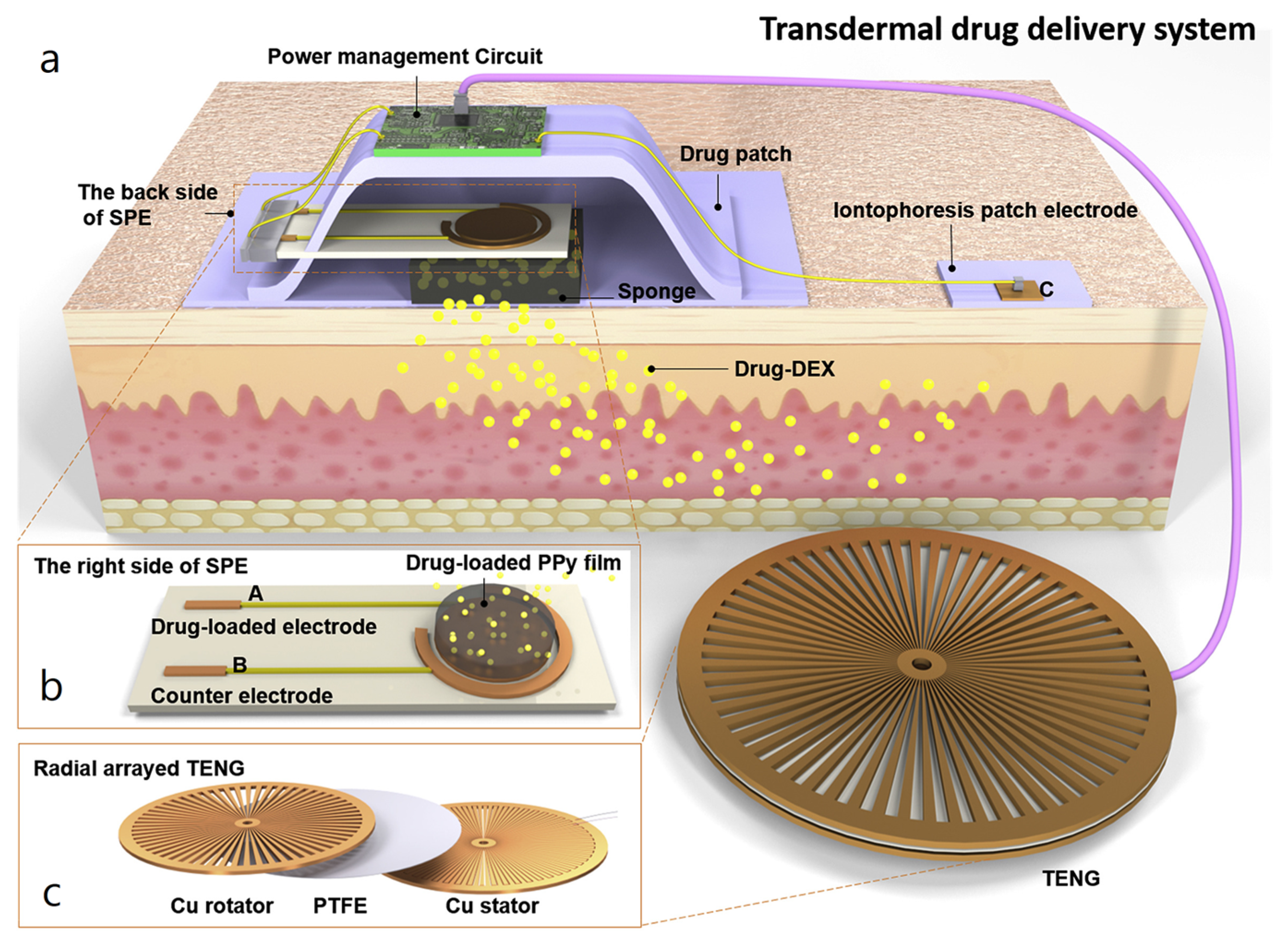
  105. Ouyang, Q.; Feng, X.; Kuang, S.; Panwar, N.; Song, P.; Yang, C.; Yang, G.; Hemu, X.; Zhang, G.; Yoon, H.S.; et al. Self-powered, on-demand transdermal drug delivery system driven by triboelectric nanogenerator. Nano Energy 2019, 62, 610–619. [Google Scholar] [CrossRef]
  106. Hu, W.; Wei, X.; Zhu, L.; Yin, D.; Wei, A.; Bi, X.; Liu, T.; Zhou, G.; Qiang, Y.; Sun, X.; et al. Enhancing proliferation and migration of fibroblast cells by electric stimulation based on triboelectric nanogenerator. Nano Energy 2019, 57, 600–607. [Google Scholar] [CrossRef]
  107. Bai, Y.; Chen, S.; Wang, H.; Wang, E.; Kong, X.; Gai, Y.; Qu, X.; Li, Q.; Xue, S.; Guo, P.; et al. Chemical warfare agents decontamination via air mircoplasma excited by a triboelectric nanogenerator. Nano Energy 2022, 95, 106992. [Google Scholar] [CrossRef]
  108. Chen, J.; Wang, P.; Li, J.; Wang, C.; Wang, J.; Zhang, D.; Peng, Y.; Wang, B.; Wu, Z. Self-powered antifouling UVC pipeline sterilizer driven by the discharge stimuli based on the modified freestanding rotary triboelectric nanogenerator. Nano Energy 2022, 95, 106969. [Google Scholar] [CrossRef]
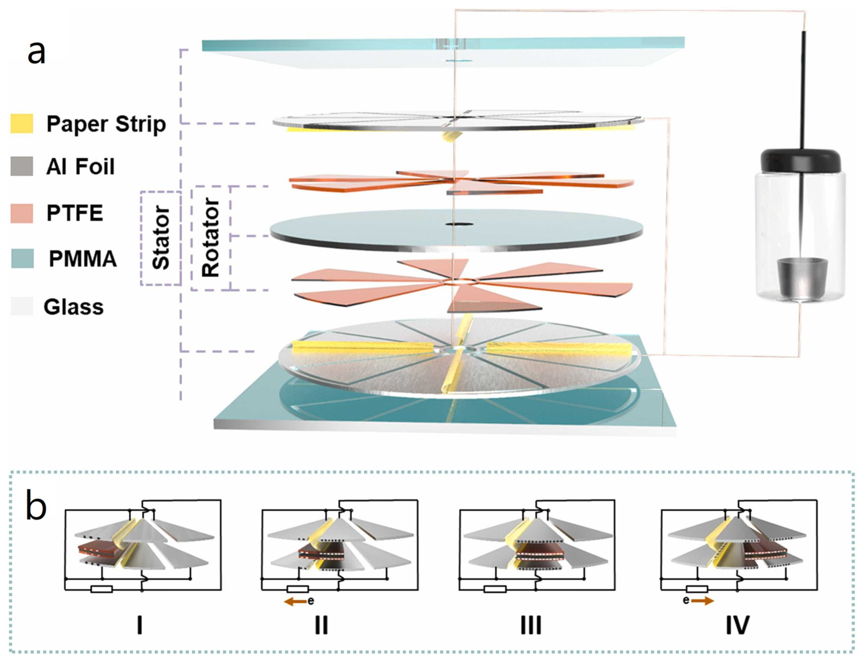
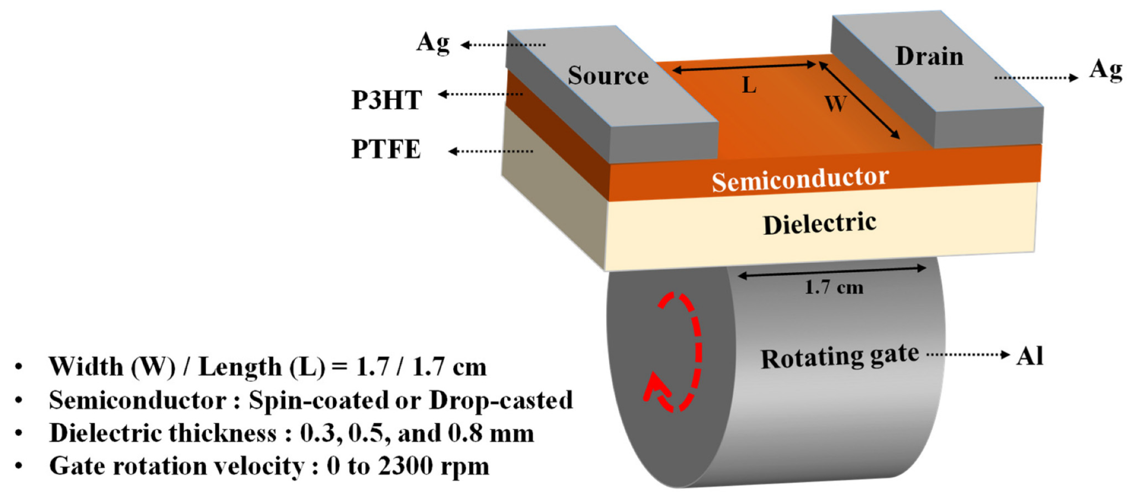
  109. Shin, H.; Kim, D.Y. Rotating Gate-Driven Solution-Processed Triboelectric Transistors. Sensors 2022, 22, 3309. [Google Scholar] [CrossRef]
Figure 1. Working modes of TENGs. Reproduced with permission [23]. Copyright 2018, John Wiley and Sons.
Nanoenergyadv 03 00010 g001
Figure 2. Output characteristics of a R-TENG. The effect of the number of gratings n on Qsc, Voc, C, and Qsc and C at maximum displacement (ad). The effect of external load on Qsc, VR, IR, and P output of R-TENG (eh). Voltage-charge curve (i), average power for different number of gratings (j), figure of merit (k) and optimal average power (l) for different numbers of gratings. Reproduced with permission [26]. Copyright 2021, Elsevier.
Nanoenergyadv 03 00010 g002
Figure 3. The effect of different materials and ambient conditions on the output characteristics of TENGs. (a) Open-voltage circuit of R-TENGs with dielectric-conductor, (b) dielectric-dielectric design and (c) comparison of the output for the different design types. (d) Chemical structures of electrification materials. (e) Open circuit voltage and charge for devices fabricated from differently manufactured FEP films. (f) Stability and wear resistance of the R-TENG. Reproduced with permission [28]. Copyright 2021, John Wiley and Sons.
Nanoenergyadv 03 00010 g003
Figure 4. Comparison between R-TENGs and EMGs. (a,c,e,g) Schematic, fundamental principles, governing equations and the respective terms for EMGs. (b,d,f,h) Schematic, fundamental principles, governing equations and the respective terms for R-TENGs. Reproduced with permission [30]. Copyright 2014, John Wiley and Sons.
Nanoenergyadv 03 00010 g004
Figure 5. Schematic representation of the charge injection method using two R-TENGs. (iiv) Working principles of the pumping TENG. (vviii) Working principles of the main TENG when the injected charges reach saturation. Reproduced with permission [31]. Copyright 2020, John Wiley and Sons.
Nanoenergyadv 03 00010 g005
Figure 6. Wind harvesting R-TENG, with PTFE rotating flaps. (a) Schematic of the R-TENG. (b) SEM image of the ICP-treated PTFE. (c) photograph of the device. Reproduced with permission [36]. Copyright 2013, American Chemical Society.
Nanoenergyadv 03 00010 g006
Figure 7. Water driven R-TENG with radial flaps. (a) Schematic and (b) photograph of the R-TENG. Reproduced with permission [37]. Copyright 2016, Elsevier.
Nanoenergyadv 03 00010 g007
Figure 8. Wind harvesting R-TENG using radial polyimide flaps and PTFE. (a) Schematic diagram. (b) SEM image of the ICP-RIE treated PTFE layer. (c) Schematic detail of the stator. (d) Photograph of the rotator and (e) the stator. Reproduced with permission [38]. Copyright 2020, Springer Nature.
Nanoenergyadv 03 00010 g008
Figure 9. The cylindrical design of R-TENG presented by Zhang et al. (a) Schematic. (b) SEM image of modified PTFE surface. (c) Output performance under 800 rpm. Inset: Photograph of the device and enlarged view of the voltage peaks. (d) Output voltages for different rotation speeds. Reproduced with permission [42]. Copyright 2014, American Chemical Society.
Nanoenergyadv 03 00010 g009
Figure 10. (a) Core–shell structure, utilizing nanopatterned PTFE, proposed by Bai et al. Reproduced with permission [43]. Copyright 2013, American Chemical Society. (be) Cylindrical, non-contact TENG for energy harvesting from hydraulics. Reproduced with permission [44]. Copyright 2020, Springer Nature. (f) Cylindrical, oscillating R-TENG for water wave energy harvesting. Reproduced with permission [45]. Copyright 2020, AIP Publishing.
Nanoenergyadv 03 00010 g010
Figure 11. Water wave energy harvesting R-TENG, utilizing a set of magnets for frequency multiplication. (a) Schematic and (b,c) photographs of the device. (d) Working principle of the R-TENG. (e) Electricity generation process. Reproduced with permission [46]. Copyright 2022, Elsevier.
Nanoenergyadv 03 00010 g011
Figure 12. (a) Cylindrical R-TENG utilizing water for contact electrification. Reproduced with permission [50]. Copyright 2016, Elsevier. (b,c) Illustration, photograph and schematic of R-TENG using symmetrical storage compartments for liquid-contact electrification. Reproduced with permission [51]. Copyright 2021, Elsevier.
Nanoenergyadv 03 00010 g012
Figure 13. One of the first reported radially segmented disk R-TENG designs. (a) Schematic diagram. (b) SEM image of surface treated Kapton. (c) Photograph of the stator and rotator parts. (d) Working principle. Reproduced with permission [55]. Copyright 2013, American Chemical Society.
Nanoenergyadv 03 00010 g013
Figure 14. A radially segmented disk design featuring multiple radial segments and gold IDEs. (a) Schematic diagram. (b,c) Schematic detail of the IDEs. (d,e) Photographs of the stator and rotator parts. Reproduced with permission [56]. Copyright 2014, Springer Nature.
Nanoenergyadv 03 00010 g014
Figure 15. The R-TENG proposed for harvesting mechanical energy from bicycle tires during normal riding and braking modes. (a) Schematic diagram. (b) Photograph of the R-TENG. (c) Powering of LEDs in riding and braking mode. Reproduced with permission [57]. Copyright 2021, John Wiley and Sons.
Nanoenergyadv 03 00010 g015
Figure 16. A collection of different R-TENGs based on radially segmented disk design. (a) Schematic design and photographs of radially segmented R-TENG. (b) Structural design of dual rotation shaft R-TENG. (c) Soft-contact R-TENG based on the Curie effect. (d) Schematic design of heat energy harvesting R-TENG. Reproduced with permission [58,59,60,61]. Copyright 2015, Elsevier; 2021, John Wiley and Sons; 2022, Springer Naturee; 2022, Elsevier.
Nanoenergyadv 03 00010 g016
Figure 17. Multiple R-TENGs structure for water wave energy harvesting. (a,b) Schematic designs. (c) Photographs of the device, the stator and the rotor parts. (d) SEM image of surface modified PTFE film. Reproduced with permission [62]. Copyright 2019, Elsevier.
Nanoenergyadv 03 00010 g017
Figure 18. The proposed design and illustration of the working principle of a R-TENG for harvesting wind drafts created by high-speed trains. (a) Device installation and application concept. (b) Schematic diagram of the design. (c) Geometric structure design. (d) Working principle. Reproduced with permission [63]. Copyright 2021, American Chemical Society.
Nanoenergyadv 03 00010 g018
Figure 19. (ac) Radially segmented disk R-TENG with paper patches for partial soft-contact electrification. Reproduced with permission [64]. Copyright 2021, John Wiley and Sons. (df) Design featuring polyester fur for soft-contact electrification to enhance charge generation. Reproduced with permission [65]. Copyright 2021, Elsevier.
Nanoenergyadv 03 00010 g019
Figure 20. Free floating rotating TENG with VMC based on the charge injection strategy. (a) Schematic of potential application. (b) Schematic diagram of R-TENG design. (c) Working principle. (d) Schematic of the VMC. (eh) Self-excitation process in sliding mode. (i) Output charge density under different operating modes. Reproduced with permission [66]. Copyright 2021, Springer Nature.
Nanoenergyadv 03 00010 g020
Figure 21. An escapement mechanism-driven R-TENG for enhanced electrical output with upscaled frequency. Reproduced with permission [67]. Copyright 2020, John Wiley and Sons.
Nanoenergyadv 03 00010 g021
Figure 22. Schematic of contact-wireless hybrid R-TENG for wireless energy transmission. (a) Rotator and stator. (b) Ferroalloy collectors. (c,d) Photographs of the R-TENG. Reproduced with permission [68]. Copyright 2018, John Wiley and Sons.
Nanoenergyadv 03 00010 g022
Figure 23. Hybrid design combining a R-TENG and an EMG for wind energy harvesting. (a,c) Schematic designs of the device, the stator and the rotator parts. (b) SEM image of surface treated FEP. Reproduced with permission [74]. Copyright 2017, American Chemical Society.
Nanoenergyadv 03 00010 g023
Figure 24. A hybrid R-TENG/EMG for water wave energy scavenging, based on swinging motion. (a) Illustration of water-wave energy harvesting application. (b) Schematic design of the device. (c) Shell with copper electrodes. (d) Rotor. (e) Copper coils. (f) Neodymium magnets. (g) Rabbit hair brush. Reproduced with permission [75]. Copyright 2021, Elsevier.
Nanoenergyadv 03 00010 g024
Figure 25. Energy harvesting from the heaving motion of a buoy, by a hybrid R-TENG/EMG design. (a) Illustration of potential application. (b,c) Schematic design of the R-TENG/EMG. (d) Working principle for energy production. (e) Photograph of the device. Reproduced with permission [76]. Copyright 2021, Elsevier.
Nanoenergyadv 03 00010 g025
Figure 26. Wind energy harvester comprised of a hybrid R-TENG/EMG combination. (a) Schematic design. (b) Photograph of (i) the rotor, (ii) the stator and (iii) the assembled R-TENG. Reproduced with permission [77]. Copyright 2021, Elsevier.
Nanoenergyadv 03 00010 g026
Figure 27. Pinwheel design of a hybrid R-TENG/EMG wind energy harvester. (a) Schematic design. (b) SEM image of surface treated FEP. (c) Photograph of the device. Reproduced with permission [78]. Copyright 2019, Elsevier.
Nanoenergyadv 03 00010 g027
Figure 28. Radially segmented disk R-TENG combined with an EMG and vertical flaps for wind and water energy harvesting. (a) Schematic design. (b) SEM image of nanostructured PTFE surface. (c) SEM image of aluminum nanopores. (d) Illustration of potential application. (e) Photograph of the device. Reproduced with permission [79]. Copyright 2016, American Chemical Society.
Nanoenergyadv 03 00010 g028
Figure 29. Multilayered structure of hybrid R-TENG/PENG wind energy harvester. (a) Schematic design. (b) Working principle of TENG and PENG operation and photograph of the device. Reproduced with permission [80]. Copyright 2019, Elsevier.
Nanoenergyadv 03 00010 g029
Figure 30. (a) Schematic of the rotary TENG developed by Lin et al. and (b,c) SEM images of the patterned FEP and aluminum surfaces, respectively. Reproduced with permission [87]. Copyright 2014, American Chemical Society.
Nanoenergyadv 03 00010 g030
Figure 31. Illustration, image, and schematic of the working principle of a R-TENG utilizing PTFE ball bearings. (a) Schematic design. (b) Photograph of the device. (c) Illustration of the charge generation mechanism. (d) COMSOL calculation of charge distribution. (e) Simulation results of open-circuit potential on the bearings. Reproduced with permission [91]. Copyright 2015, Elsevier.
Nanoenergyadv 03 00010 g031
Figure 32. Cylindrical PTFE bearings used as the electrification layer in R-TENG design. (a) Illustration of potential applications. (b) Schematic of the energy harvester and the power management system. (c) Illustration of the proposed installation of the R-TENG. (d) Photograph of the device. Reproduced with permission [92]. Copyright 2022, MDPI.
Nanoenergyadv 03 00010 g032
Figure 33. Radially arrayed R-TENG angle and rotation speed sensor. (a) Schematic design. (b) Photograph of the rotator. (c) Photograph of the stator. (d) SEM image of Cu foil. Inset: Enlarged SEM image. (e) SEM image of the PTFE particles on the surface of FEP. Reproduced with permission [94]. Copyright 2015, John Wiley and Sons.
Nanoenergyadv 03 00010 g033
Figure 34. Self-powered angle sensor for use in robotic limbs. (a) Illustration of potential applications. (b) Schematic design. Insets: Photographs of the IDEs and SEM image of the surface treated Kapton film. (c,d) Working principle of the dual TENGs. Reproduced with permission [96]. Copyright 2020, John Wiley and Sons.
Nanoenergyadv 03 00010 g034
Figure 35. (ad) Pendulum-shaped TENG developed by He et al. for use as a tilt-angle sensor. Reproduced with permission [97]. Copyright 2018, John Wiley and Sons, (e) Chemical analysis sensor based on liquid–solid interaction. Reproduced with permission [98]. Copyright 2019, American Chemical Society.
Nanoenergyadv 03 00010 g035
Figure 36. Schematic of self-powered water splitting system. Reproduced with permission [102]. Copyright 2018, Elsevier.
Nanoenergyadv 03 00010 g036
Figure 37. Schematic of radially segmented disk R-TENG, used to drive an electrospinning system. (a) Schematic illustration of the energy harvester actuated electrospinning apparatus. (b) Schematic design. Insets: Schematic illustration of the Cu IDEs. (c) Photograph of the stator and rotator parts. (d) Photograph of assembled R-TENG. Reproduced with permission [103]. Copyright 2017, American Chemical Society.
Nanoenergyadv 03 00010 g037
Figure 38. Schematic of the design and the operating principle of R-TENG used to manipulate the transportation of droplets. (a) Illustration of the electric brush. (b) Schematic design of the droplet-based transport system. (c) Schematic design of the R-TENG. (d) Illustration of the droplet tracking process. Reproduced with permission [104]. Copyright 2021, Royal Society of Chemistry.
Nanoenergyadv 03 00010 g038
Figure 39. An R-TENG used for controlled subdermal drug release. (a) Illustration of the complete system, including subdermal patches, R-TENG and power management system. (b) The right side of the integrated system. (c) Schematic of the rotor and stator parts and the assembled R-TENG. Reproduced with permission [105]. Copyright 2019, Elsevier.
Nanoenergyadv 03 00010 g039
Figure 40. R-TENG utilized in the electrical stimulation of L929 cells (ac) and its effect on their proliferation and migration (d,e). Reproduced with permission [106]. Copyright 2019, Elsevier.
Nanoenergyadv 03 00010 g040
Figure 41. Schematic of the R-TENG developed for microplasma excitation. (a) Schematic diagram of the device. (b) Working mechanism. Reproduced with permission [107]. Copyright 2022, Elsevier.
Nanoenergyadv 03 00010 g041
Figure 42. Operating principle and components of a wind-driven UVC lamp for water decontamination. (iiv) The charge generation is illustrated in different phases of the transient sliding motion. Reproduced with permission [108]. Copyright 2022, Elsevier.
Nanoenergyadv 03 00010 g042
Figure 43. Schematic of the rotating triboelectric gate of a transistor. Reproduced with permission [109]. Copyright 2022, MDPI.
Nanoenergyadv 03 00010 g043
Table 1. R-TENGs in energy harvesting applications.
ReferenceDielectricsElectrodesMode of OperationElectrical Output Characteristics
Xie et al.
[12]
PTFE (ICP)
PET
AluminumContactVoc: 250 V
Qsc: 140 nC
Isc: 0.25 mA (1 GΩ)
P: 12 mW (1 MΩ)
Rodrigues et al.
[37]
PTFE
Nylon 6.6
Kapton
AluminumContactVoc: 102.2 V (44 L/min)
Qsc: 8.1 μC (44 L/min)
Isc: 120 mA/m2 (44 L/min)
Pd: 6.1 W/m2 (44 L/min)
Du et al.
[38]
Kapton
PTFE (ICP)
CopperContactVoc: 280 V (120 rpm)
Qsc: -
Isc: 78 μA (120 rpm)
Pd: 2.54 W/m2 (120 rpm, 5 MΩ)
Zhang et al.
[42]
PTFE (ICP)AluminumContactVoc: 55 V (800 rpm)
Qsc: -
Isc: 20 μA (800 rpm)
Pd: 3.1 mW/m2 (800 rpm)
Bai et al.
[16]
PTFE (PTFE nanoparticles)CopperContactVoc: 400 V (1000 rpm)
Qdsc: 24.5 μC
Jsc: 90 μA (1000 rpm)
Pd: 36.9 W/m2 (1000 rpm)
Zhang et al.
[44]
FEP (ICP)CopperNon-ContactVoc: 1661 V (2000 rpm)
Qsc: 46 nC
Isc: 12 μA (2000 rpm)
Pd: 16.5 mW/m2 (2000 rpm)
Feng et al.
[45]
FEPCopperNon-ContactVoc: 120 V
Qsc: 46 nC
Isc: 1.52 μA
P: 159 μW (100 MΩ)
Jung et al.
[46]
FEPAluminumNon-ContactVoc: 395 V (0.33 Hz)
Qsc: 46 nC
Isc: 7.3 μA (0.33 Hz)
Pd: 117 μW (0.33 Hz, 70 MΩ)
Kim et al.
[50]
PTFE
Water
AluminumContactVoc: 27.2 V (200 rpm)
Qsc: -
Isc: 3.84 μA (200 rpm)
P: 19.1 μW (200 rpm, 20 MΩ)
Le et al.
[51]
PVDF (phase inversion)
Water
CopperContactVoc: 1.5 V (18 rpm)
Qsc: 2.03 nC (18 rpm)
Jsc: 11.94 nA/cm2 (18 rpm)
Pd: 18.48 nW/cm2 (18 rpm, 20 MΩ)
Lin et al. [55]Kapton (ICP)Gold
Aluminum
ContactVoc: 230 V (500 rpm)
Qdsc: 40 μC/m2 (500 rpm)
Jsc: 29 mA/m2 (1000 rpm)
Pd: 1 W/m2 (10 MΩ)
Zhu el al.
[56]
FEPGold
Copper
ContactVoc: 850 V (3000 rpm)
Qsc: 0.32 μC
Isc: 3 mA (3000 rpm)
Pd: 19 mW/m2 (3000 rpm, 0.8 MΩ)
Zhou et al. [57]PTFECopper
Steel
Contact & Non-ContactVoc: 300 V (150 rpm)
Qsc: 24 μC/m2 (150 rpm)
Isc: 60 μA (150 rpm)
P: 2.29 mW (150 rpm, 20 MΩ)
Kuang et al.
[58]
PTFE-ContactVoc: 200 V (500 rpm)
Qsc: -
Isc: 0.75 mA (500 rpm)
Pd: -
Yong et al.
[59]
FEPCopperContactVoc: 306 V
Qsc: -
Isc: 32 μA
P: 5.2 mW
Cao et al.
[60]
FEP
Rabbit fur
CopperContactVoc: -
Qsc: 389 nC (30 rpm)
Ιsc: 3.23 μA (30 rpm)
P: 14. 8 μW (30 rpm, 1.1 GΩ)
Lin et al.
[62]
PTFE (ICP)
Nylon
CopperNon-ContactVoc: 160 V
Qsc: 75 nC
Isc: 1.5 μA
P: 74 μW (100 MΩ)
Zhang et al.
[63]
PTFE
Kapton
Copper
Aluminum
ContactVoc: 1200 V (600 rpm)
Qsc: 2.2 μC
Isc: 0.35 mA (600 rpm)
Pavg: 47 mW (1 MΩ)
Feng et al.
[64]
PTFE
Paper
AluminumNon-ContactVoc: 2352 V (600 rpm)
Qsc: 197 nC (600 rpm)
Isc: 133 μA (600 rpm)
P: 120 mW (600 rpm, 30 MΩ)
Li et al.
[65]
PTFE
Nylon Polyester fur
CopperNon-ContactVAC: 10 kV (900 rpm)
Qsc: 516 nC (900 rpm)
Isc: 71 μA (900 rpm)
P: 201.8 mW (600 rpm, 110 MΩ)
Long et al.
[66]
PTFE
Nylon
Copper
Aluminum
Non-ContactVR: 470 V (300 rpm, 10 MΩ)
Qsc: 1 μC (300 rpm)
Isc: 76 μA (300 rpm)
P: 34.68 mW (300 rpm, 30 MΩ)
Han et al.
[67]
PTFE (nanopatterned)
Nylon (nanopatterned)
AluminumNon-ContactVoc: 320 V (0.067 Hz)
Qdsc: 2.84 μC/m2 (0.067 Hz)
Jsc: 0.59 mA/m2 (0.067 Hz)
Pd: 41 mW/m2 (0.067 Hz, 33 MΩ)
Jie et al.
[68]
PTFE
PP
Tin
Gold
Non-ContactVoc: 17.5 V (500 rpm)
Qsc: -
Isc: 3 μA (500 rpm)
Pd: 21.8 mW/m2 (500 rpm, 7 MΩ)
Hybrid Energy Harvester Designs
ReferenceCombination DielectricsElectrodesMaximum electrical output characteristics
Li et al.
[61]
R-TENG and EMGFEPCopperVoc: -
Ιsc: -
PdTENG: 313 μW (6 ΜΩ)
PdEMG: 4.3 mW (680 Ω)
Cao et al.
[74]
R-TENG and EMGFEPCopperVoc: 48 V (250 rpm)
Ιsc: 1 mA (250 rpm)
PHybrid: 13 mW (250 rpm, 8 kΩ)
Feng et al.
[75]
R-TENG and EMGFEP
Rabbit fur
CopperVoc: -
Ιsc: -
PdHybrid: 0.23 W/m3 (0.1 Hz, ~100 ΜΩ)
Zhao et al.
[76]
R-TENG and EMGPTFE
Nylon
CopperVoc: -
Ιsc: -
PdTENG: 10 W/m3 (8 MΩ)
PdEMG: 4.19 W/m3 (100 Ω)
Fang et al.
[77]
R-TENG and EMGFEP
Nylon
AluminumVoc: 683 V (47.4 V)
Ιsc: -
PdHybrid: 0.27 W/m3 (267 rpm, 60 MΩ)
Guo et al.
[78]
R-TENG and EMGFEPCopperVoc: -
Ιsc: -
PdTENG: 0.12 mW/g
PdEMG: 0.26 mW/g
Zhang et al.
[79]
R-TENG and EMGPTFE (ICP)
Polyurethane
AluminumVR: 3.5 V (700 Ω)
ΙR: 5 mA (700 Ω)
PHybrid: 55.7 W/m3 (1000 rpm, 700 Ω)
Zhao et al.
[80]
R-TENG and PiezoelectricPTFE
PET
Gold
Aluminum
Voc: 210 V (100 rpm)
Ιsc: 395 μA (100 rpm)
PdHybrid: 6.04 mW/cm2 (100 rpm, ~250 kΩ)
Table 2. R-TENGs in sensing applications.
ReferenceType of R-TENGType of SensorParametersMode of OperationElectrical Output Characteristics
Lin et al.
[87]
Radially segmented sliding diskDisplacement and Rotation speedJsc amplitude and frequencyNon-contactVoc: 220 V
Jsc: 13 mA/m2
Pd: 1.22 W/m2 (2 MΩ)
Lu et al.
[88]
Radially segmented sliding diskRotation speedIsc frequencyContactVoc: 39 V
Isc: 15.6 μA (AC amplitude)
Pmax: 377.7 μW (600 kΩ)
Xie et al.
[89]
Radially segmented sliding diskRotation speedVoc frequency
Isc frequency
ContactVoc: 130 V
Isc: 150 μA (AC amplitude)
Xuan et al.
[90]
Radially segmented sliding diskRotation speed (Temperature)Isc amplitude and frequencyNon-contactVoc: 226.2 V
Isc: 12.3 μA (AC amplitude)
Qsc: 78.4 nC
Pmax: 538.6 nW (40 ΜΩ)
Meng et al.
[91]
BearingsRotation speedIsc frequencyContactIsc: 70 nA (AC amplitude)
Qsc: 2.7 μC
Xin et al.
[92]
BearingsRotation speedVoc frequencyContactVoc: 150 V
Isc: 2 μA (AC amplitude)
Pmax: 107 μW (~700 ΜΩ)
Lee et al.
[93]
Radially segmented sliding diskAngleVoc frequencyContactVoc: 180 V
Isc: 0.4 μA (AC amplitude)
Qsc: 65 nC
Wu et al.
[94]
Radially arrayed sliding diskAngleVoc amplitudeContactVoc: 20 V
Hou et al.
[95]
Radially segmented pendulumAngleVoc frequencyContactVoc: 150 V
Isc: 0.4 μA (AC amplitude)
Wang et al.
[96]
Radially segmented sliding diskAngleVoc frequency
Phase difference
ContactVoc: 123.09 V
He et al.
[97]
Radially segmented pendulumAngleVoc amplitude
Isc amplitude
ContactVoc: 83.6 V
Isc: 8.46 μA (AC amplitude)
Pmax: 35.2 mW/m2 (10 ΜΩ)
Wang et al.
[98]
TubularChemical compositionVoc amplitudeContactVoc: 228 V
Isc: 11.5 μA (AC amplitude)
Pmax: 37 mW (120 ΜΩ)
Disclaimer/Publisher’s Note: The statements, opinions and data contained in all publications are solely those of the individual author(s) and contributor(s) and not of MDPI and/or the editor(s). MDPI and/or the editor(s) disclaim responsibility for any injury to people or property resulting from any ideas, methods, instructions or products referred to in the content.

