Article

Doped-Cellulose Acetate Membranes as Friction Layers for Triboelectric Nanogenerators: The Influence of Roughness Degree and Surface Potential on Electrical Performance

by
Iuri Custodio Montes Candido
1,
Andre Luiz Freire
1,
Carlos Alberto Rodrigues Costa
2 and
Helinando Pequeno de Oliveira
1,*
1
Institute of Materials Science, Universidade Federal do Vale do São Francisco—UNIVASF, Juazeiro 48902-300, BA, Brazil
2
Brazilian Nanotechnology National Laboratory (LNNano), Brazilian Center for Research in Energy and Materials (CNPEM), Campinas 13083-100, SP, Brazil
*
Author to whom correspondence should be addressed.
Nanoenergy Adv. 2024, 4(2), 196-208; https://doi.org/10.3390/nanoenergyadv4020012
Submission received: 21 February 2024 / Revised: 25 May 2024 / Accepted: 6 June 2024 / Published: 20 June 2024

Abstract

:
The development of more efficient friction layers for triboelectric nanogenerators is a complex task, requiring a careful balance of various material properties such as morphology, surface roughness, dielectric constant, and surface potential. In this study, we thoroughly investigated the use of cellulose acetate modified with different concentrations of zinc oxide and titanium dioxide to enhance energy harvesting for the TENG. The results indicate that the roughness degree is influenced by the homogeneous degree/aggregation level of doping agents in cellulose acetate membranes, leading to the best performance of open circuit voltage of 282.8 V, short-circuit current of 3.42 µA, and power density of 60 µW/cm2 for ZnO-doped cellulose acetate membranes.

1. Introduction

In recent years, triboelectric nanogenerators (TENGs) have been considered a transformation technology in harvesting mechanical movement for conversion into electric energy. This process is established by the coupling effect of contact electrification and electrostatic induction derived from Maxwell’s displacement current theory [1,2,3,4]. The most promising materials for use in triboelectric nanogenerators must combine an excellent capability to gain or lose electrons, high surface area, roughness, and an adequate surface distribution of charges that make possible the generation, transfer, storage, and minimal dissipation of charges along with the TENG operation [5]. Consequently, different strategies for producing tribopairs [6] must combine charge transfer additives and storage components into friction layers, avoiding the dissipation of accumulated charges along with the triboelectrification process.
Cellulose is the most abundant natural polymer on Earth, and its derivatives have been considered potential candidates for the development of bio-triboelectric nanogenerators [7,8,9] with advantages relative to the biodegradability, edible behavior [10], low cost, and environmentally friendly behavior. In addition, cellulose-based materials are characterized by the mutual ability to act as an electrogiving or electron-losing component for the TENGs [11]. Given this weak triboelectric behavior of the cellulose, different methods for additive incorporation have been explored [12] and applied to control the dielectric permittivity and surface roughness of the resulting material. One of the most common strategies for the production of cellulose acetate (CA)-based TENGs is based on the electrospun growth of cellulose acetate fibers as raw materials to be paired with negatively charged fibers of MXene [13] or by the impregnation with different fillers such as the ZnO to be applied in the control the roughness and polarizability of the friction layers [14]. The surface modification of cellulose paper has been explored in the adsorption of ZnCl2 on the cellulose fibers, allowing the growth of ZnO domains on support [15].
Another possibility in controlling surface roughness is reported by Varghese et al. [16], which describes the production of cellulose acetate nanofibers paired with micropatterned PDMS disposed of as micropyramids and microdomes. Li et al. [5] explored a multilayered fiber-based device in which charge–transport and charge–storage layers improve the transfer rate and the storage depth of the device. The development of composites based on electrospun cellulose acetate/carbon nanotubes is also applied as a TENG for human motion detection [17] with alternatives based on the blending of cellulose acetate with chitosan as electron-donating components [18]. Moreover, the surface engineering of cellulose-based devices represents another critical strategy to control the roughness degree of the resulting friction layers. The development of electrospun fibers of cellulose-based derivatives [17], aerogels [18], nanofibrils [6], aerogel papers [19], gel-based electrodes [1], and dielectric modulation/surface modification by incorporation of fillers such as carbon nanotubes [17], zinc oxide [15,20], and titanium dioxide [21] are some examples of methods applied in the improvement of the output performance of cellulose-based friction layers.
Herein, cellulose acetate films were prepared by a casting method entailing the dispersion of additives (ZnO and TiO2) into the polymeric solution at low and high concentrations to evaluate the influence of morphology/surface modification/dielectric regulation of the friction layers on the overall triboelectric performance of the resulting TENG. As a result, a complex balance between surface potential and roughness can be considered a critical factor in defining the performance of the resulting positive friction layer. The best response was observed for the sample prepared with ZnO/CA at a high content level (5 wt%), in which an open circuit voltage of 282.8 V was observed for open circuit conditions, and 3.42 µA was observed for short circuit currents.

2. Materials and Methods

2.1. Materials

Cellulose acetate and titanium dioxide (purity > 99.5% with 21 nm particle size) were purchased from Sigma-Aldrich (St. Louis, MO, USA), zinc oxide (p.a. (purity > 99%)) was purchased from Vetec (Rio de Janeiro, Brazil), and acetone was purchased from Êxodo Científica (Sumaré, Brazil). All the solutions were prepared with Milli-Q water. Ecoflex™ 00-30 silicone rubber was purchased from Smooth-On, Inc. (Macungie, PA, USA).

2.2. Preparation of CA Membranes

CA membranes were fabricated using the casting technique: 1 g of cellulose acetate powder was dissolved in 25 mL of acetone. The mixture was blended in an appropriate vessel for 2 h, followed by a 30 min ultrasonication until it reached a good dispersion. The resulting solution was subsequently poured into a glass Petri dish for casting. Then, the dishes were left to dry for 24 h at ambient temperature.

2.3. Preparation of ZnO/CA and TiO2/CA Membranes

ZnO and TiO2 powder, separately, were added to the dissolved CA solution according to the procedure reported in Ref. [22] with some modifications, as follows: ZnO/CA and TiO2/CA membranes of nanoparticles (low level—1 mg (0.1 wt%), and high level—50 mg (5 wt%)) which were dispersed within 1 g of CA into 25 mL of acetone. The mixture was also prepared in a suitable reactor and stirred for 2 h to prepare pure cellulose membranes. Subsequently, a step of ultrasonication of 30 min was conducted to achieve a uniform and well-dispersed solution. The resulting solution was then poured into a glass Petri dish for the casting process and left to dry for 24 h at ambient temperature (a schematic representation of this process is summarized in Figure 1a).

2.4. Preparation of the Ecoflex Film

A total of 3 g each of parts A and B of the Ecoflex 00-30 elastomer was mixed for 20 min. A sandpaper support of (4 × 4) cm2 was cut and deposited on an acrylic sheet using scotch tape to be applied as a mold with characteristic roughness for the resulting film. The prepared solution was poured onto the sandpaper mold and allowed to dry on a flat surface at room temperature for 24 h (a schematic representation of this process is shown in Figure 1b).

2.5. Production of CA–TENG Prototype

The TENG device’s support was assembled using arch-shaped sections (eye shape) sourced from 250 mL soft drink PET bottles. The inner smooth part of the bottle was cut (7 cm × 3.5 cm) and received Al electrodes (3 cm × 2 cm)—the working area of the device is 6 cm2, and the air gap is 3 cm. Following this step, the Ecoflex film, pure CA membrane, ZnO/CA, and TiO2/CA membranes were cut to match the dimensions of the Al electrodes. Subsequently, the membranes were disposed into the inner surface of the plastic bottle section. Aluminum strips were then affixed to the electrodes at both ends to establish electrical connections. The configuration of the device and the disposition of the friction layers are shown in Figure 1c.

2.6. Characterization Techniques

The harvested output voltage from the TENG was measured by a digital oscilloscope (Rigol MSO1104Z, Suzhou, China), with the input channel connected via a 100 MΩ probe LF–250S (Minipa, São Paulo, Brazil). For short-circuit current measurement, the oscilloscope was connected to a circuit using an LMC6001 current preamplifier, as reported in Ref. [23]. The atomic force microscopy (AFM, Park Systems, Santa Clara, CA, USA, model NX-10) technique was used to measure the influence of fillers on the overall surface roughness of the positive friction layers, and Kelvin probe force microscopy (AFM, Park Systems, model NX-10) was used to measure surface potential. The Kelvin probe force microscopy (KPFM) data were performed using a platinum–iridium-coated tip of silicon with a force of 2.8 N/m, frequency of 75 kHz in images of 2.0 µm × 0.5 µm@400 × 100 pixels, and 10 µm × 2 µm@500 × 100 pixels at 0.2 Hz. The analysis of KPFM data was carried out using Gwyddion software (version 2.61). The experiments considered four different samples for each concentration of the additive.

3. Results

Thermal and Structural Characterization of CB and Modified CB Membranes

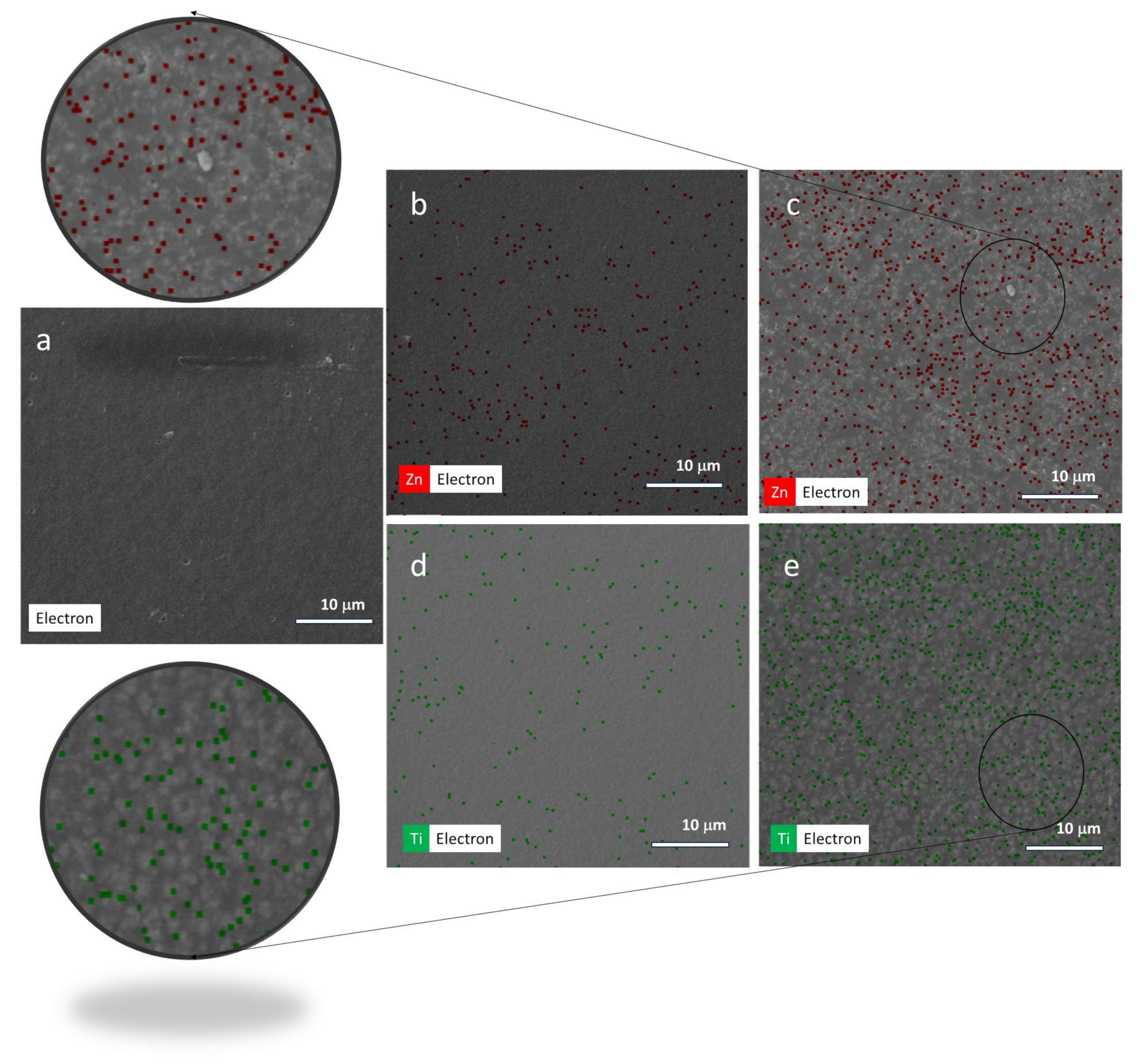
The spatial identification of metal oxide nanoparticles into membranes was preliminarily evaluated by Energy-dispersive X-ray Spectroscopy/Scanning Electron Microscopy (EDX/SEM) microscopies in which overlaid images of red/green dots are assigned to ZnO and TiO2 nanoparticles, respectively. As shown in Figure 2, and as expected, the pristine sample is free of both additives. The comparison of images at progressive incorporation of ZnO (0.1 wt%—Figure 2b and 5 wt%—Figure 2c) confirmed the increasing density of red dots. Similarly, the higher density of green dots was observed for TiO2-doped membranes—Figure 2d for 0.1 wt% of TiO2 and Figure 2e for 5 wt% of TiO2.
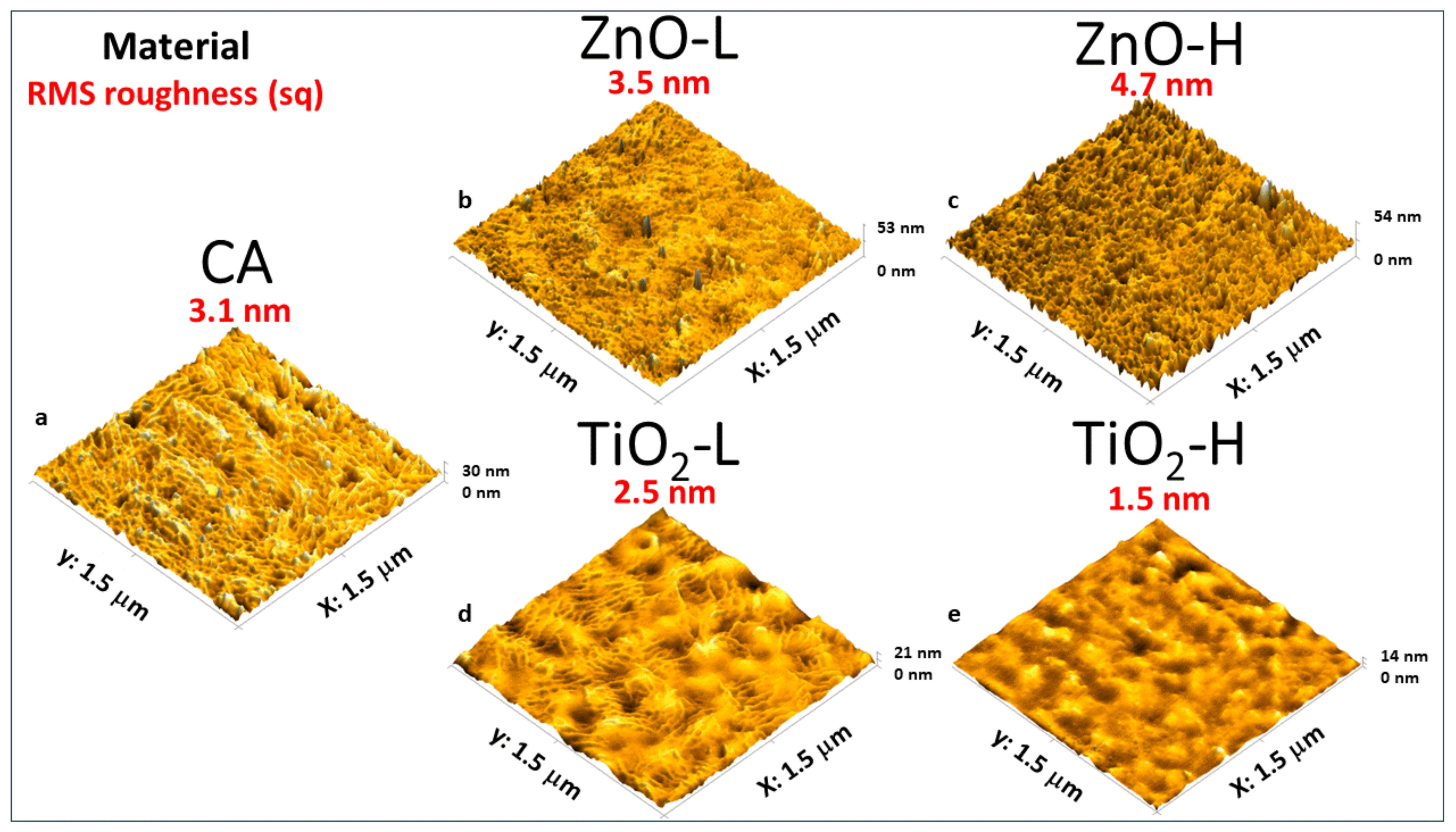
The roughness degree of membranes prepared with different filler content was evaluated by AFM images shown in Figure 3a–e for negative control—CA (a), ZnO-L—0.1 wt% (b), ZnO-H—5 wt% (c), TiO2-L—0.1 wt% (d), and TiO2-H—5 wt% (e). The values described in each image represent the RMS roughness. As shown, the progressive incorporation of ZnO fillers increases the roughness degree of the resulting material (from 3.1 nm to 4.7 nm). On the other hand, the behavior is opposite for samples prepared at increasing concentrations of TiO2: the roughness in the overall range of variation of additive content decreases from 3.1 nm to 1.5 nm, probably due to the loss of homogeneity in the particle distribution/agglomeration similarly to the reported for BaTiO3-based TENG systems [24].
In addition to the roughness degree of the samples measured by AFM, the comparison of CA-based membranes with different fillers at different concentrations was provided by KPFM, which measures the contact potential difference (VCPD) defined as the potential applied between the AFM tip and the sample to nullify the voltage between parts. From the VCPD value, the work function of the sample s a m p l e   can be calculated from Equation (1)
s a m p l e   = p r o b e   e V C P D
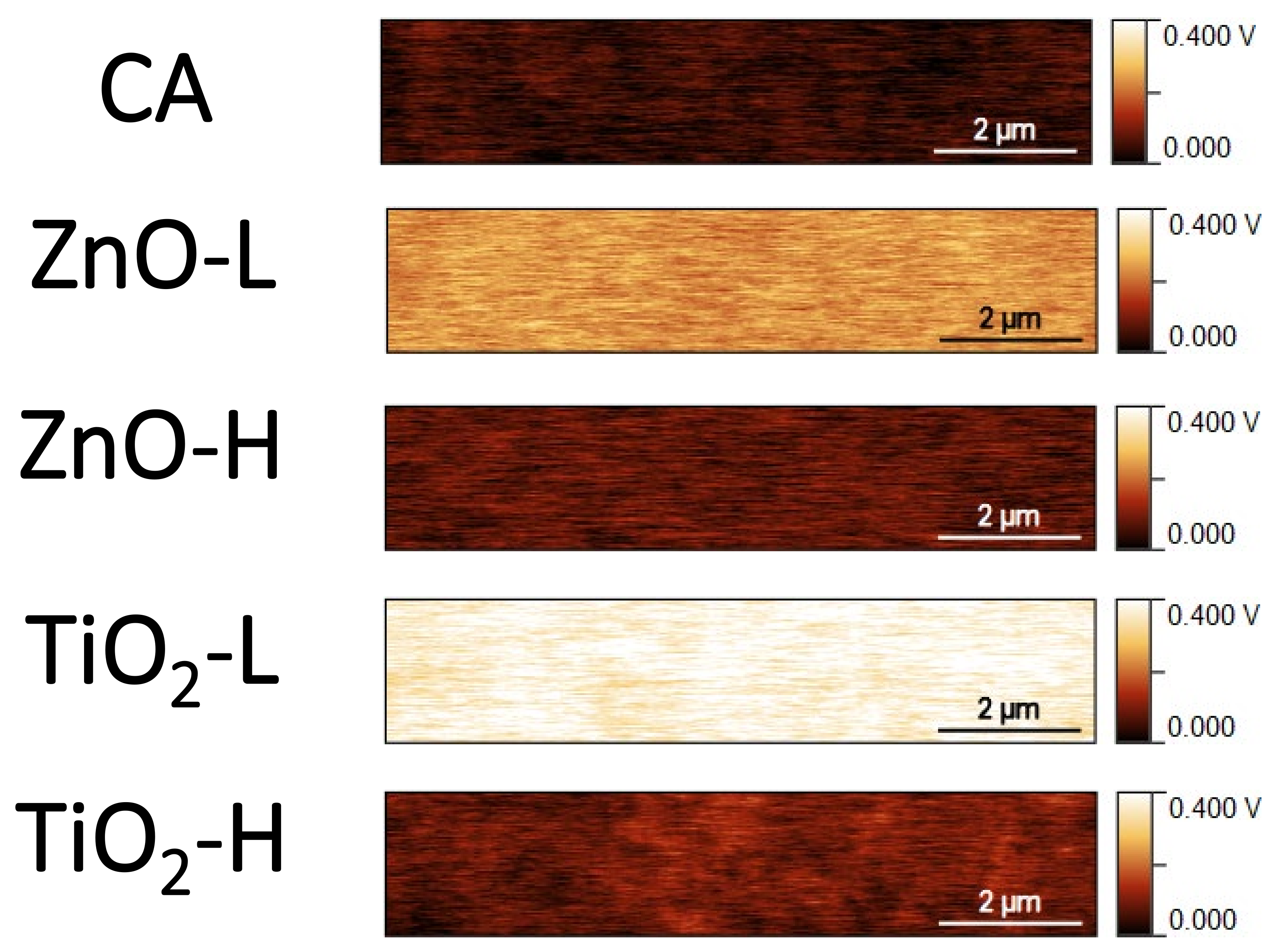
Here, p r o b e   is the work function of the tip, and e is the electron charge that requires a vacuum condition to be conveniently evaluated from the corresponding experimental conditions. Higher values for VCPD mean that the material’s work function is reduced, being considered a material with a higher tendency to donate electrons as a positive friction layer in TENG. As shown in the color map for the distribution of VCPD values on modified surfaces (Figure 4), a low value for VCPD of the pure CA with an overall increase in its value with the incorporation of additives (TiO2 and ZnO) at low concentration (0.1 wt%) was observed.
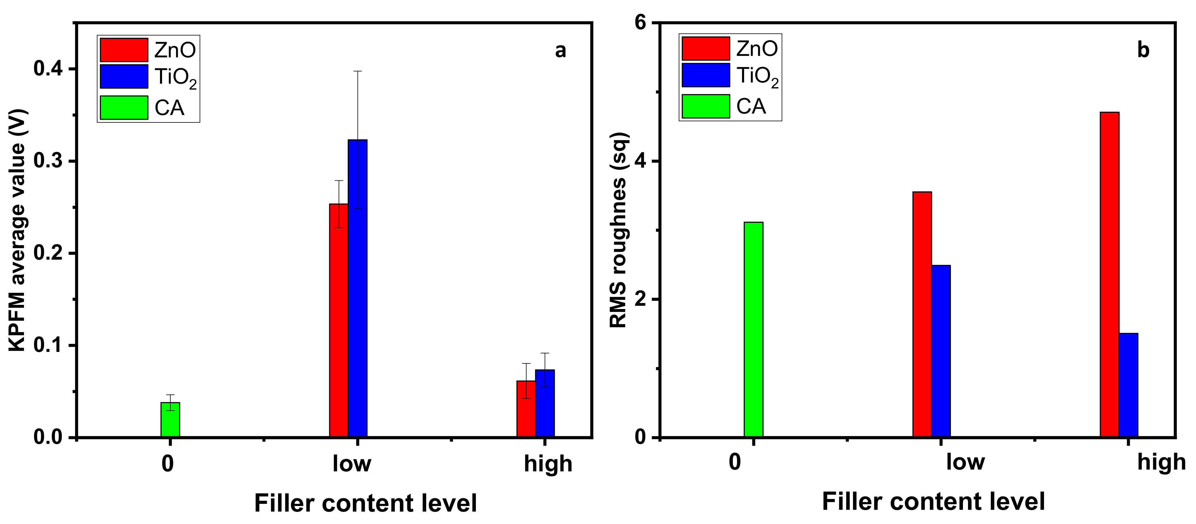
Under progressive incorporation of additives, the VCPD is reduced for both additives at a concentration of 5 wt%. Values for the KPFM average value are summarized in Figure 5a, with the corresponding standard deviation calculated from measured values. The VCPD for pure CA is 0.04 V, with an increase in its value observed for incorporating additives at low concentrations (0.25 V for ZnO and 0.32 V for TiO2). Under the progressive incorporation of additives (5 wt%), these values are reduced to 0.06 V for ZnO and 0.07 V for TiO2. Despite this reduction, it is worth mentioning that the value remains higher than that obtained for pure CA.
If considering the dependence of the TENG with the KPFM response, it would be expected that the best result for samples prepared with 0.1 wt% of filler (ZnO or TiO2). However, the performance of the TENG mutually depends on the surface charge density and the morphology characteristics of the resulting friction layers. Values for RMS roughness obtained from AFM images (Figure 3) are represented in Figure 5b.
As can be seen from a comparison of results in Figure 5a,b, it is possible to observe that a local maximum in the KPFM average is common for both additives. On the other hand, the slopes are inverted in the roughness measurement; while an overall increase in the slope is observed with an increasing incorporation of ZnO, the negative slope is obtained with the progressive incorporation of TiO2. Consequently, there is a general reduction in the performance devices of TiO2 under progressive incorporation of filler (mutual reduction in the KPFM and roughness). In contrast, the opposite behavior indicates a competition between work function value and roughness degree in ZnO-doped CA.
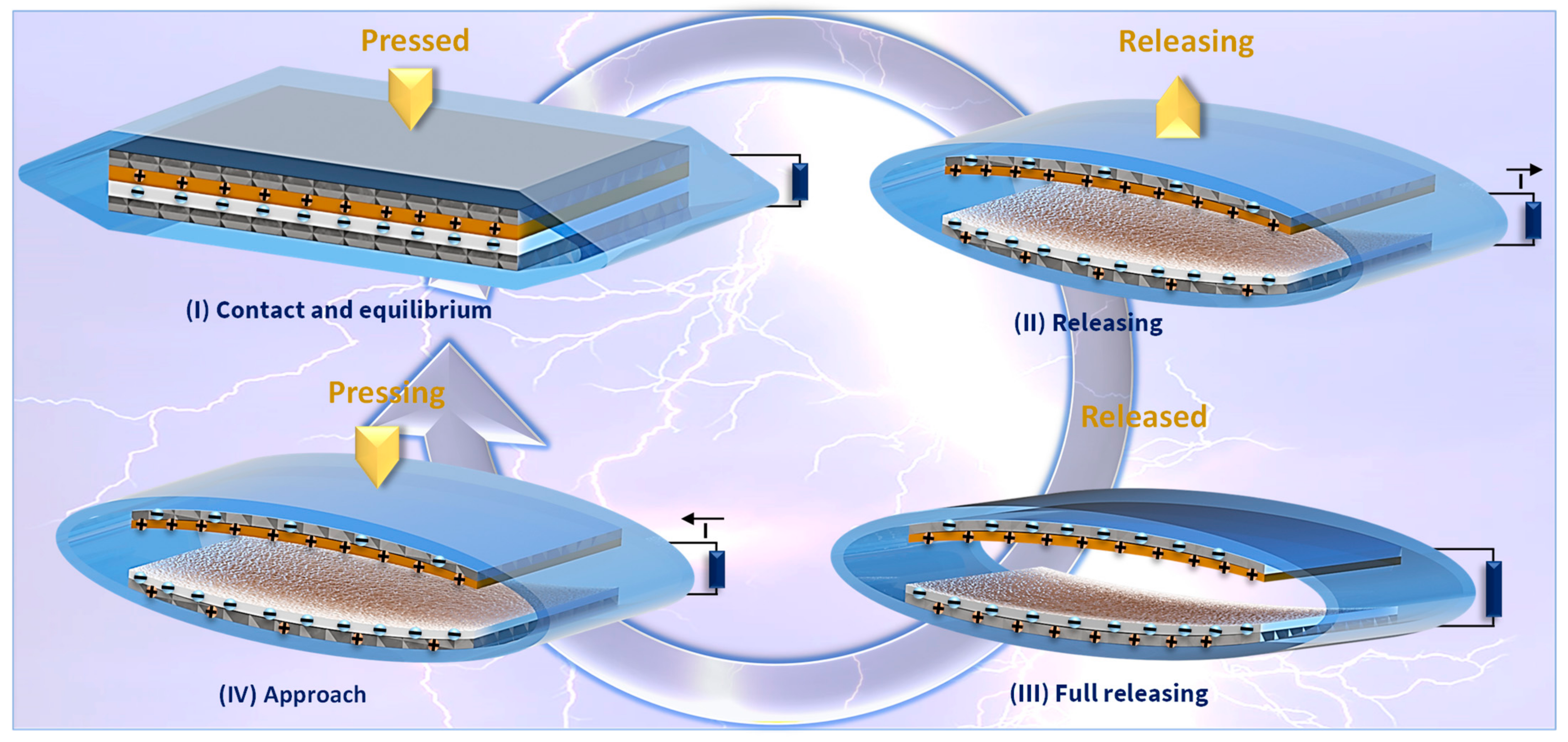
The performance of the resulting TENG was evaluated from a contact–separation triboelectric nanogenerator with operation mechanisms drawn in Figure 6, in which the pure CA and modified CA membrane were applied as a positive tribolayer with Ecoflex disposed of as a tribonegative layer. The general mechanism is established after a first contact in which electrons are transferred to the Ecoflex layer. At the same time, positive charges are distributed on the surface of CA and modified CA membranes. The two friction layers are separated under the release of the parts, and charges induced in the Al-based back electrodes are forced by an external potential difference to circulate in a resistance load under the release of friction layers. Under the complete separation of tribopairs, a new configuration of charges takes place after current circulation, and under reversion of the movement obtained with the pressing of tribopairs, an inverted current is established in the load resistance, characterizing the operation of an AC generator. The improvement in the electrical output performance of TENG is explored by the progressive incorporation of high dielectric permittivity fillers (ZnO and TiO2) applied in the control of the dielectric layer doping with the dispersion of prototypes of “nanocapacitors” into the cellulose acetate membrane—that improves the charge density of the friction tribolayers—with direct influence on surface potential of the membranes. This process of dielectric property tuning can also be considered a surface engineering step since it affects the material’s roughness.
Preliminary assays were performed to define the best excitation frequency of the reciprocating linear motor. With the results shown in Figure S1 for sample ZnO (5 wt%), it is possible to observe that the best results are observed for samples excited at 7 Hz. The influence of the air gap on the device and the thickness of the tribonegative layer are evaluated in Figure S2. Based on this result, all device characterization was performed at 7 Hz.
The open circuit voltage and short circuit current for devices prepared at different content of fillers are shown in Figure 7a and Figure 7b, respectively. As shown in Figure 7a, the progressive incorporation of TiO2 from zero to the maximum concentration (5 wt%) results in a progressive reduction in the maximal value of voltage—media of positive peaks are shown in Figure 7c. On the other hand, under progressive incorporation of ZnO powder, the voltage is positively affected, reaching a maximum voltage in the order of 282.8 V for sample ZnO prepared with a high content of the filler (5 wt%). Relative to the short circuit current, similar behavior was observed in both experimental systems at increasing concentration: while the current decreases at progressive incorporation of TiO2, the opposite behavior was obtained for the incorporation of ZnO with an increase in the current from 1.87 µA to 3.42 µA (see Figure 7d). This trend was confirmed for samples with intermediate concentrations of TiO2 and ZnO (1% wt of fillers). Consequently, the medium of transferred charge per cycle (shown in Figure 7e) follows the same behavior with a positive slope for progressive incorporation of filler (charge increases as the content of ZnO increases). In contrast, the opposite behavior is observed for the TiO2-increasing content. From these data, it is possible to calculate the transferred work per cycle (Wa–b = q(Va − Vb)), where q is the transferred charge and Va − Vb is the difference of potential per cycle. For those that are purely CA-based, the work performed is 3.4 mJ. Under the progressive incorporation of ZnO, this value varies to 4.21 mJ (ZnO-L) and 8.05 mJ (ZnO-H), which characterizes an improvement of 137% in the device’s energy conversion. On the other hand, incorporating TiO2 reduces the overall transferred work to 2.91 mJ (TiO2-L) and 1.53 mJ (TiO2-H), characterizing a decrease of 55% in the device’s energy conversion.
It is worth mentioning from these results that the electrical performance of TENGs as a function of additives and their concentration is in agreement with the sequence observed in Figure 5b for the roughness of the resulting friction layers. As observed in Figure 5b, the roughness degree follows the order (ZnO-H > ZnO-L > CA) and agrees with the order in the performance of charge transfer—see Figure 7e (ZnO-H > ZnO-L > CA). On the other hand, for TiO2-based samples, the roughness degree follows the order (TiO2-H < TiO2-L < CA), which agrees with the order in the performance of charge transfer for TiO2-doped CA friction layer TENGs. The strong relationship between the roughness and electrical performance of TENGs and the weak variation in the KPFM is probably due to the aggregation level of nanoparticles at increasing concentration, avoiding the modulation in the surface potential. Despite this process, effective roughness modification induced by ZnO compared to TiO2 is critical in defining the best condition for applying the friction layer in TENG. Based on these results, the sample prepared with a high concentration of ZnO (5 wt%) was considered the best tribopositive layer, and its ability to harvest energy was evaluated for different load resistances in the range of 105 to 108 Ω. Results shown in Figure 8a for current and voltage versus load resistance indicated that increasing resistance reduced the values of output current from ~4.5 µA to ~1.5 µA with an opposite variation observed for output voltage from 0 to 160 V, allowing that a crossover between curves can be observed. This typical response results in a maximum output power density of 60 µWcm−2 (as shown in Figure 8b).
Other important aspects to consider for the resulting device were the ability to transfer charge to conventional electronic components and the retention of the capability to harvest energy after several cycles of operation. Results in Figure 8c confirm that negligible variation in the voltage was observed after continuous excitation of TENG for 6000 cycles in constant contact–separation steps (good performance after long-term operation).
The ability to transfer charge was evaluated from the connection of the output of the TENG via a full bridge rectifier to different conventional capacitors (1 µF, 4.7 µF, and 10 µF) that were charged by rectified signal generated by excitation at 7 Hz that results in the accumulation for a complete period of 60 s. As shown in Figure 8d, the continuous operation of the TENG resulted in an increase in the voltage on capacitor terminals with the higher values observed for capacitors with lower capacitance (V1 µF > V 4.7 µF >V10 µF). This behavior is expected due to the fixed amount of charge transferred per cycle and an inverse relationship with the value of capacitance (V = q/C), where q is the accumulated charge on terminals and C is the capacitance value. Another standard application is shown in Video S1, in which the device switches on 10 LEDs.
As noted in the literature, the typical procedure applied in the electrical output improvement of TENGs is based on the direct relationship between electrical performance and surface roughness [24,25,26,27,28] that contributes to the improvement in the available area [26] for the accumulation of high charge density at interfaces. However, it is worth mentioning that highly rough surfaces in TENGs can return a decrease in the contact area between the two triboelectric surfaces [29]. Consequently, under the controlled creation of nano- and micro-roughness patterns, it is possible to optimize the output performance, being considered a limiting condition for reducing the contact area of tribolayers [29]. In addition to the roughness degree, an important aspect to be considered is the dielectric layer doping technology methods [30] based on the incorporation of high dielectric permittivity (ZnO and TiO2), creating the effect of dispersion of nanocapacitors that reinforce the interface polarization. The reinforcement provided by ZnO and TiO2 on modified CA was evaluated from the direct measurement of capacitance at 1 kHz of the modified tribolayer. While an initial capacitance of 127.3 pF for pure CA membrane, this value was improved to 132.6 pF for the sample (ZnO 5 wt%) and 159.2 pF for TiO2 5 wt%., in an indication that the output performance of TENGs is a result of a complex balance between charge density, dielectric doping effects, and roughness events induced by the distribution of nanostructures along with the membrane. The comparison of VOC, ISC, and power density of cellulose-based TENGs reported in the literature is summarized in Table S1 (see refs. [31,32,33,34,35,36,37]), in which corresponding modifications were provided to CA to reinforce the dielectric properties and roughness degree. As can be seen, the power density output for this work reached the maximum value for samples CA/ZnO (60.0 μW/cm2) followed by pristine CA (25.8 μW/cm2) and (23.5 μW/cm2) for CA/TiO2, confirming that improved surface roughness provided by the ZnO incorporation into cellulose acetate represents a vital strategy to reach improved electrical output performance in comparison with corresponding reported systems

4. Conclusions

The eco-friendly behavior of cellulose-based materials represents an essential advantage for the production of TENGs. The reinforcement in the surface roughness of the resulting friction layer of CA membranes can be controlled by the incorporation of ZnO nanoparticles with promising results in terms of voltage (282.8 V), current (3.42 µA), and power density (60.0 μW/cm2) that introduces an improvement of 132% in the overall performance of the device in comparison with pristine CA-based TENGs. The resulting devices are characterized by long-term efficiency (negligible variation in the response after 6000 cycles of use) and the ability to transfer charge to conventional electronic devices.

Supplementary Materials

The following supporting information can be downloaded at: https://www.mdpi.com/article/10.3390/nanoenergyadv4020012/s1, Figure S1. Comparison of voltage (a) and current (b) of TENG prepared with friction layer of ZnO (5 wt%) as a function of frequency of excitation; Figure S2. Comparison of open circuit voltage for TENGs prepared at different combinations of conditions for CA-doped tribopositive layers and Ecoflex tribonegative layer: the influence of air gap in the device for TENGs doped with (a) ZnO and (b) TiO2 and the influence of the thickness of tribonegative layer on the response of TENGs doped with (c) ZnO and (d) TiO2; Table S1. Comparison of voltage, current, and power density for cellulose acetate-based triboelectric nanogenerators with experimental systems explored in this work; Video S1. Powering 10 LEDs by operating the Triboelectric Nanogenerator.

Author Contributions

Conceptualization I.C.M.C., A.L.F., C.A.R.C. and H.P.d.O.; methodology I.C.M.C., A.L.F., C.A.R.C. and H.P.d.O.; investigation I.C.M.C., A.L.F., C.A.R.C. and H.P.d.O.; writing—original draft preparation, I.C.M.C., A.L.F. and H.P.d.O.; writing—review and editing, H.P.d.O.; visualization, I.C.M.C., A.L.F., C.A.R.C. and H.P.d.O.; supervision, H.P.d.O.; project administration, H.P.d.O.; funding acquisition, H.P.d.O. All authors have read and agreed to the published version of the manuscript.

Funding

This work was supported by CAPES, FACEPE, FAPESB, and CNPq. Research supported by LNNano—Brazilian Nanotechnology National Laboratory (CNPEM/MCTI) during the use of the AFM/KPFM open access facility, HPO thanks CNPq (Grant No. 303997/2021-4) for the funds.

Data Availability Statement

Data are contained within the article or Supplementary Materials.

Conflicts of Interest

The authors declare no conflicts of interest.

References

  1. Qin, Y.; Zhang, W.; Liu, Y.; Zhao, J.; Yuan, J.; Chi, M.; Meng, X.; Du, G.; Cai, C.; Wang, S.; et al. Cellulosic Gel-Based Triboelectric Nanogenerators for Energy Harvesting and Emerging Applications. Nano Energy 2023, 106, 108079. [Google Scholar] [CrossRef]
  2. Candido, I.C.M.; Oliveira, G.d.S.; Ribeiro, S.J.L.; Cavicchioli, M.; Barud, H.S.; Silva, L.G.; de Oliveira, H.P. PVA-Silk Fibroin Bio-Based Triboelectric Nanogenerator. Nano Energy 2023, 105, 108035. [Google Scholar] [CrossRef]
  3. Candido, I.C.M.; Oliveira, G.D.S.; Viana, G.G.; Da Silva, F.A.G.; Da Costa, M.M.; De Oliveira, H.P. Wearable Triboelectric Nanogenerators Based on Chemical Modification of Conventional Textiles for Application in Electrically Driven Antibacterial Devices. ACS Appl. Electron. Mater. 2022, 4, 334–344. [Google Scholar] [CrossRef]
  4. Candido, I.C.M.; Piovesan, L.F.; Freire, A.L.; Fotius, J.A.A.; de Lima, J.J.I.; Barud, H.S.; de Oliveira, H.P. Biodegradable Hyaluronic Acid-Based Triboelectric Nanogenerator as Self-Powered Temperature Sensor. Mater. Today Commun. 2023, 36, 106855. [Google Scholar] [CrossRef]
  5. Li, Z.; Zhu, M.; Qiu, Q.; Yu, J.; Ding, B. Multilayered Fiber–Based Triboelectric Nanogenerator with High Performance for Biomechanical Energy Harvesting. Nano Energy 2018, 53, 726–733. [Google Scholar] [CrossRef]
  6. Yao, C.; Hernandez, A.; Yu, Y.; Cai, Z.; Wang, X. Triboelectric Nanogenerators and Power-Boards from Cellulose Nanofibrils and Recycled Materials. Nano Energy 2016, 30, 103–108. [Google Scholar] [CrossRef]
  7. Zhou, J.; Wang, H.; Du, C.; Zhang, D.; Lin, H.; Chen, Y.; Xiong, J. Cellulose for Sustainable Triboelectric Nanogenerators. Adv. Energy Sustain. Res. 2022, 3, 2100161. [Google Scholar] [CrossRef]
  8. Freire, A.L.; Lima, L.R.; Candido, I.C.M.; Silva, L.G.; Ribeiro, S.J.L.; Carrilho, E.; Oliveira, T.L.; Fernando, L.; De Oliveira, C.; Barud, H.S.; et al. Metal-Free, Bio-Triboelectric Nanogenerator Based on a Single Electrode of Bacterial Cellulose Modified with Carbon Black. Nanoenergy Adv. 2024, 4, 110–121. [Google Scholar] [CrossRef]
  9. Zhao, H.; Kwak, J.; Conradzhang, Z.; Brown, H.; Arey, B.; Holladay, J. Studying Cellulose Fiber Structure by SEM, XRD, NMR and Acid Hydrolysis. Carbohydr. Polym. 2007, 68, 235–241. [Google Scholar] [CrossRef]
  10. Lamanna, L.; Pace, G.; Ilic, I.K.; Cataldi, P.; Viola, F.; Friuli, M.; Galli, V.; Demitri, C.; Caironi, M. Edible Cellulose-Based Conductive Composites for Triboelectric Nanogenerators and Supercapacitors. Nano Energy 2023, 108, 108168. [Google Scholar] [CrossRef]
  11. Zhang, M.; Du, H.; Liu, K.; Nie, S.; Xu, T.; Zhang, X.; Si, C. Fabrication and Applications of Cellulose-Based Nanogenerators. Adv. Compos. Hybrid Mater. 2021, 4, 865–884. [Google Scholar] [CrossRef]
  12. Vatankhah, E.; Tadayon, M.; Ramakrishna, S. Boosted Output Performance of Nanocellulose-Based Triboelectric Nanogenerators via Device Engineering and Surface Functionalization. Carbohydr. Polym. 2021, 266, 118120. [Google Scholar] [CrossRef] [PubMed]
  13. Sardana, S.; Kaur, H.; Arora, B.; Aswal, D.K.; Mahajan, A. Self–Powered Monitoring of Ammonia Using an MXene/TiO2/Cellulose Nanofiber Heterojunction-Based Sensor Driven by an Electrospun Triboelectric Nanogenerator. ACS Sens. 2022, 7, 312–321. [Google Scholar] [CrossRef] [PubMed]
  14. Jakmuangpak, S.; Prada, T.; Mongkolthanaruk, W.; Harnchana, V.; Pinitsoontorn, S. Engineering Bacterial Cellulose Films by Nanocomposite Approach and Surface Modification for Biocompatible Triboelectric Nanogenerator. ACS Appl. Electron. Mater. 2020, 2, 2498–2506. [Google Scholar] [CrossRef]
  15. Lin, C.; Chen, D.; Hua, Z.; Wang, J.; Cao, S.; Ma, X. Cellulose Paper Modified by a Zinc Oxide Nanosheet Using a ZnCl2-Urea Eutectic Solvent for Novel Applications. Nanomaterials 2021, 11, 1111. [Google Scholar] [CrossRef] [PubMed]
  16. Varghese, H.; Hakkeem, H.M.A.; Chauhan, K.; Thouti, E.; Pillai, S.; Chandran, A. A High-Performance Flexible Triboelectric Nanogenerator Based on Cellulose Acetate Nanofibers and Micropatterned PDMS Films as Mechanical Energy Harvester and Self–Powered Vibrational Sensor. Nano Energy 2022, 98, 107339. [Google Scholar] [CrossRef]
  17. Bai, Y.; Zhou, Z.; Zhu, Q.; Lu, S.; Li, Y.; Ionov, L. Electrospun Cellulose Acetate Nanofibrous Composites for Multi-Responsive Shape Memory Actuators and Self–Powered Pressure Sensors. Carbohydr. Polym. 2023, 313, 120868. [Google Scholar] [CrossRef] [PubMed]
  18. Zhang, L.; Liao, Y.; Wang, Y.; Zhang, S.; Yang, W.; Pan, X.; Wang, Z.L. Cellulose II Aerogel-Based Triboelectric Nanogenerator. Adv. Funct. Mater. 2020, 30, 2001763. [Google Scholar] [CrossRef] [PubMed]
  19. Shi, K.; Zou, H.; Sun, B.; Jiang, P.; He, J.; Huang, X. Dielectric Modulated Cellulose Paper/PDMS-Based Triboelectric Nanogenerators for Wireless Transmission and Electropolymerization Applications. Adv. Funct. Mater. 2020, 30, 1904536. [Google Scholar] [CrossRef]
  20. Baro, B.; Khimhun, S.; Das, U.; Bayan, S. ZnO Based Triboelectric Nanogenerator on Textile Platform for Wearable Sweat Sensing Application. Nano Energy 2023, 108, 108212. [Google Scholar] [CrossRef]
  21. Liu, H.; Feng, Y.; Shao, J.; Chen, Y.; Wang, Z.L.; Li, H.; Chen, X.; Bian, Z. Self-Cleaning Triboelectric Nanogenerator Based on TiO2 Photocatalysis. Nano Energy 2020, 70, 104499. [Google Scholar] [CrossRef]
  22. Alahmadi, N.; Hussein, M.A. Hybrid Nanocomposite Membranes Containing Cellulose Acetate@CuO/ZnO for Biological Interest. J. Mater. Res. Technol. 2022, 21, 4409–4418. [Google Scholar] [CrossRef]
  23. Mallineni, S.S.K.; Behlow, H.; Podila, R.; Rao, A.M. A Low-Cost Approach for Measuring Electrical Load Currents in Triboelectric Nanogenerators. Nanotechnol. Rev. 2018, 7, 149–156. [Google Scholar] [CrossRef]
  24. Tantraviwat, D.; Ngamyingyoud, M.; Sripumkhai, W.; Pattamang, P.; Rujijanagul, G.; Inceesungvorn, B. Tuning the Dielectric Constant and Surface Engineering of a BaTiO3/Porous PDMS Composite Film for Enhanced Triboelectric Nanogenerator Output Performance. ACS Omega 2021, 6, 29765–29773. [Google Scholar] [CrossRef]
  25. Chen, S.; Huang, S.; Wu, H.; Pan, W.; Wei, S.; Peng, C.; Ni, I.; Murti, B.T.; Tsai, M.; Wu, C.; et al. A Facile, Fabric Compatible, and Flexible Borophene Nanocomposites for Self-Powered Smart Assistive and Wound Healing Applications. Adv. Sci. 2022, 9, 2201507. [Google Scholar] [CrossRef] [PubMed]
  26. Mishra, S.; Supraja, P.; Haranath, D.; Kumar, R.R.; Pola, S. Effect of Surface and Contact Points Modification on the Output Performance of Triboelectric Nanogenerator. Nano Energy 2022, 104, 107964. [Google Scholar] [CrossRef]
  27. Chen, H.; Xu, Y.; Bai, L.; Jiang, Y.; Zhang, J.; Zhao, C.; Li, T.; Yu, H.; Song, G.; Zhang, N.; et al. Crumpled Graphene Triboelectric Nanogenerators: Smaller Devices with Higher Output Performance. Adv. Mater. Technol. 2017, 2, 1700044. [Google Scholar] [CrossRef]
  28. Sun, J.; Tu, K.; Büchele, S.; Koch, S.M.; Ding, Y.; Ramakrishna, S.N.; Stucki, S.; Guo, H.; Wu, C.; Keplinger, T.; et al. Functionalized Wood with Tunable Tribopolarity for Efficient Triboelectric Nanogenerators. Matter 2021, 4, 3049–3066. [Google Scholar] [CrossRef]
  29. Zhou, J.; Lu, C.; Lan, D.; Zhang, Y.; Lin, Y.; Wan, L.; Wei, W.; Liang, Y.; Guo, D.; Liu, Y.; et al. Enhancing the Output Performance of a Triboelectric Nanogenerator Based on Modified Polyimide and Sandwich–Structured Nanocomposite Film. Nanomaterials 2023, 13, 1056. [Google Scholar] [CrossRef]
  30. Suo, X.; Li, B.; Ji, H.; Mei, S.; Miao, S.; Gu, M.; Yang, Y.; Jiang, D.; Cui, S.; Chen, L.; et al. Dielectric Layer Doping for Enhanced Triboelectric Nanogenerators. Nano Energy 2023, 114, 108651. [Google Scholar] [CrossRef]
  31. He, X.; Zou, H.; Geng, Z.; Wang, X.; Ding, W.; Hu, F.; Zi, Y.; Xu, C.; Zhang, S.L.; Yu, H.; et al. A Hierarchically Nanostructured Cellulose Fiber-Based Triboelectric Nanogenerator for Self-Powered Healthcare Products. Adv. Funct. Mater. 2018, 28, 1805540. [Google Scholar] [CrossRef]
  32. Shi, K.; Huang, X.; Sun, B.; Wu, Z.; He, J.; Jiang, P. Cellulose/BaTiO3 Aerogel Paper Based Flexible Piezoelectric Nanogenerators and the Electric Coupling with Triboelectricity. Nano Energy 2019, 57, 450–458. [Google Scholar] [CrossRef]
  33. Chen, S.; Jiang, J.; Xu, F.; Gong, S. Crepe Cellulose Paper and Nitrocellulose Membrane-Based Triboelectric Nanogenerators for Energy Harvesting and Self-Powered Human-Machine Interaction. Nano Energy 2019, 61, 69–77. [Google Scholar] [CrossRef]
  34. Zhang, J.; Hu, S.; Shi, Z.; Wang, Y.; Lei, Y.; Han, J.; Xiong, Y.; Sun, J.; Zheng, L.; Sun, Q.; et al. Eco-Friendly and Recyclable All Cellulose Triboelectric Nanogenerator and Self-Powered Interactive Interface. Nano Energy 2021, 89, 106354. [Google Scholar] [CrossRef]
  35. Varghese, H.; Abdul Hakkeem, H.M.; Farman, M.; Thouti, E.; Pillai, S.; Chandran, A. Self-Powered Flexible Triboelectric Touch Sensor Based on Micro-Pyramidal PDMS Films and Cellulose Acetate Nanofibers. Results Eng. 2022, 16, 100550. [Google Scholar] [CrossRef]
  36. Behera, S.A.; Kim, H.-G.; Jang, I.R.; Hajra, S.; Panda, S.; Vittayakorn, N.; Kim, H.J.; Achary, P.G.R. Triboelectric Nanogenerator for Self-Powered Traffic Monitoring. Mater. Sci. Eng. B 2024, 303, 117277. [Google Scholar] [CrossRef]
  37. Ruthvik, K.; Babu, A.; Supraja, P.; Navaneeth, M.; Mahesh, V.; Uday Kumar, K.; Rakesh Kumar, R.; Manmada Rao, B.; Haranath, D.; Prakash, K. High-Performance Triboelectric Nanogenerator Based on 2D Graphitic Carbon Nitride for Self-Powered Electronic Devices. Mater. Lett. 2023, 350, 134947. [Google Scholar] [CrossRef]
Figure 1. Scheme for preparation of friction layers of CA and modified CA (a), Ecoflex friction layer (b), and the assembly of friction layers in a contact–separation triboelectric nanogenerator (c).
Nanoenergyadv 04 00012 g001
Figure 2. Overlaid EDX images of cellulose acetate-based membranes: (a) pure, (b) ZnO-L (0.1 wt%), (c) ZnO-H (5 wt%), (d) TiO2-L (0.1 wt%), and (e) TiO2-H (5 wt%).
Nanoenergyadv 04 00012 g002
Figure 3. AFM image and RMS roughness value for membranes of pure CA (a), ZnO/CA (0.1 wt%) (b), ZnO/CA (5 wt%) (c), TiO2/CA (0.1 wt%) (d), and TiO2/CA (5 wt%) (e).
Nanoenergyadv 04 00012 g003
Figure 4. Color map for measured surface voltage by KPFM on the surface of pristine CA membrane (CA) and modified with ZnO with lower concentration (ZnO-L)—0.1 wt% and higher concentration (ZnO-H)—5 wt%, lower concentration (TiO2-L)—0.1 wt% and higher concentration (TiO2-H)—5 wt% of TiO2.
Nanoenergyadv 04 00012 g004
Figure 5. (a) KPFM average values for pure membrane (CA—green bar), and doped CA with TiO2 (blue bar) and ZnO (red bar) at two levels of filler content (0.1 wt%—low level and 5 wt%—high level), and (b) corresponding RMS roughness values.
Nanoenergyadv 04 00012 g005
Figure 6. Schematic representation of the complete cycle of the contact–separation process applied on friction layers disposed in a double-electrode TENG configuration with the AC generation under pressing/releasing steps used in the device—the arrows in yellow indicate the direction of the resulting force.
Nanoenergyadv 04 00012 g006
Figure 7. (a) Open circuit voltage for pure CA and modified CA with different content of ZnO and TiO2, (b) short circuit current for pure CA and modified CA with different content of ZnO and TiO2, (c) medium values for open circuit voltage for TENGs based on pure CA and modified CA friction layers, (d) medium values for short circuit currents for TENGs based on pure CA and modified CA friction layers, and (e) calculated transferred charge per cycle of TENGs based on pure CA and modified CA friction layers.
Nanoenergyadv 04 00012 g007
Figure 8. (a) Curves of voltage (in black) and current (in red) for TENG connected to different load resistances, (b) resulting power density as a function of load resistance, (c) degradation assay with the repeated excitation of TENG at 7 Hz and measured open circuit voltage, and (d) voltage on capacitor terminals for capacitors with nominal values of 1 µF, 4.7 µF, and 10 µF.
Nanoenergyadv 04 00012 g008
Disclaimer/Publisher’s Note: The statements, opinions and data contained in all publications are solely those of the individual author(s) and contributor(s) and not of MDPI and/or the editor(s). MDPI and/or the editor(s) disclaim responsibility for any injury to people or property resulting from any ideas, methods, instructions or products referred to in the content.