1. Introduction
Modern vehicles with CO2 reduction technologies, high specification levels, and new electronic driving assistants have an auxiliary battery in addition to the vehicle’s main starting battery or the high-voltage system batteries of hybrid electric vehicles. The size and specifications of the auxiliary batteries can vary and depend on the demands of the vehicle’s electrical system, and can be used as a backup battery to back up the main battery when necessary, or to supply voltage to specific vehicle systems at all times.
Almost every electric vehicle uses a conventional battery of 12 V as an ancillary power system, together with the main high-voltage battery for powering the electric engine. The auxiliary battery does not power the starting engine, nor does the electric one only power the ancillary systems, the car lights, the sound system, the computer controls, the heating and air conditioning unit, etc.
In most cases, auxiliary batteries are lead-acid units of 12 V continuous current whose output voltage is fully compatible with the ancillary systems of an electric vehicle. Lead-acid batteries, however, are heavy and suffer from low specific energy. An alternative is a small lithium-ion battery that supplies more power, is lighter, and takes up less space. This is the solution that the Tesla factory has implemented in some of the new models since 2021 [
1,
2]. The Lithium-ion cell operates at a voltage between 3.0 V and 4.2 V when fully charged, which is compatible with the operating voltage of electric vehicle ancillary systems. Nevertheless, higher voltage battery configurations are possible, thus lowering the draining current, limiting the energy losses, and reducing the weight of the wiring. To fulfill this goal, Tesla intends to implement auxiliary lithium-ion batteries of 48 V [
3].
Some Tesla models already mount auxiliary lithium-ion batteries of intermediate voltage [
4], and these models benefit from the mentioned advantages of reduced draining current, lower energy losses, and lighter wiring installation.
The charging of high- and low-voltage batteries in an electric vehicle depends on the car’s manufacturer. In conventional cars with an internal combustion engine (ICE), an electric generator produces a continuous current to charge the lead-acid battery. In electric vehicles, the high-voltage battery is charged directly from the grid.
In battery electric vehicles, since there are two batteries, the main one for powering the vehicle and the auxiliary one to service the ancillary equipment, the management of the battery charging process is more complex than in conventional cars, where the only existing battery charges from an electric generator that operates connected to the ICE.
A well-known control system regulates the battery charging process in electric vehicles. A battery isolator or relay goes between the main and the auxiliary battery. When the main battery reaches a specific voltage, usually around 13.6 V, the relay engages and diverts the extra power from the alternator to charge the auxiliary battery. A general study describes the methodology, management, and technology of battery charging in EVs [
5]. In some cases, a dual-inverter with an open-end winding motor configuration is an attractive method for supplying a higher voltage to a motor for electric vehicle (EV) applications [
6]; in others, the system uses a shared charging channel for wireless technology [
7]. An alternative method to charge the auxiliary battery from the main battery is inductive power transfer (IPT) [
8].
A literature review shows that the majority of research work focuses on the charging protocol of the main battery in electric vehicles, with little work on the charging process optimization of a dual battery block with a main and auxiliary battery. This work aims to define a protocol that optimizes the charging process of both batteries upon specific requests of energy demand, depending on driving conditions.
In this paper, we propose a new method to manage the charging process of a dual battery block for battery electric vehicles, which powers an electric vehicle and services the ancillary equipment. The charging process optimizes the energy transfer to the auxiliary battery while the vehicle runs, depending on driving conditions. To achieve this goal, the charging control system equips specific software that selects when the main battery charges the auxiliary one to avoid an excessive discharge rate while powering the vehicle.
This paper represents a contribution to the state of the art of dual battery electric vehicle power management, since it develops a new method to optimize the management of the power source for vehicle powering and ancillary equipment service.
Previous works deal with power management in fuel cell hybrid electric vehicles, applying Model Predictive Control (MPC) and Deep Reinforcement Learning (DRL) [
9,
10]; this paper, however, deals with a dual lithium battery power system, which represents an innovative situation regarding the powering of EVs, because the traditional configuration uses a single battery for vehicle power and ancillary equipment service, or a lead-acid battery for this latter use. Power battery use as the power source for vehicle motion and auxiliary battery charging represents a novelty in electric vehicle power system configuration. Additionally, power management optimization also means an innovation in the state of the art.
2. Theoretical Foundations
Electric vehicles operate with high and low power loads depending on the operational voltage. The principal unit that uses high-voltage energy is the electric engine that powers the vehicle, while the ancillary equipment operates at low voltage. The electric layout operates in a dual mode with independent circuits, which are not connected but for the wiring between the two batteries. This connection charges the auxiliary battery from the main one.
Since the auxiliary battery only supports the energy consumption of ancillary equipment, the required amount of energy is not high, which means that the current drained from the main battery to recharge the auxiliary battery is low. On the other hand, due to the higher operating voltage of the main battery, the extracted current for the auxiliary battery charging is even lower. In terms of electric magnitudes:
Panc is the power demand from the ancillary equipment and
V and
I are the voltage and current, with
aux for the auxiliary and
main for the main battery.
ηtr is the efficiency of the charge transfer from the main to the auxiliary battery.
Operating in Equation (1):
The condition established in Equation (3) shows that we can recharge the main battery due to the low draining current. The energy recovery from the regenerative braking process is a suitable way to do so.
Regenerative braking uses vehicle speed reduction, either from braking or deceleration, to generate electric current, reverting the use of the electric engine and making it operate as an electric generator. The energy conversion, however, is not perfect; therefore, only a fraction of the energy loss is recovered and converted into electric current. Mathematically:
where
m and
v represent the mass and speed of the vehicle, with
i and
f for the initial and final state,
top is the time of braking or deceleration, and
η the efficiency of the regenerative braking. The sub-index
reg accounts for the regeneration process.
Since
Ireg =
Imain, applying Ohm’s law:
In case of braking,
vf = 0; thus:
where
indicates the minimum initial vehicle speed before stopping to replace the energy extracted from the main battery when recharging the auxiliary one using regenerative braking.
3. Methodology
3.1. Control System
This methodological process bases its development on a control system design that optimizes the management process of charging a dual battery block, with both a main and auxiliary battery, of an electric vehicle. To do so, we design an electric circuit that reproduces the operational one in electric vehicles equipped with a main battery for powering the vehicle and an auxiliary one for servicing the ancillary equipment.
The simulation circuit considers the different working voltage of the two batteries and the operating current type, alternate or continuous; therefore, it includes the appropriate converters.
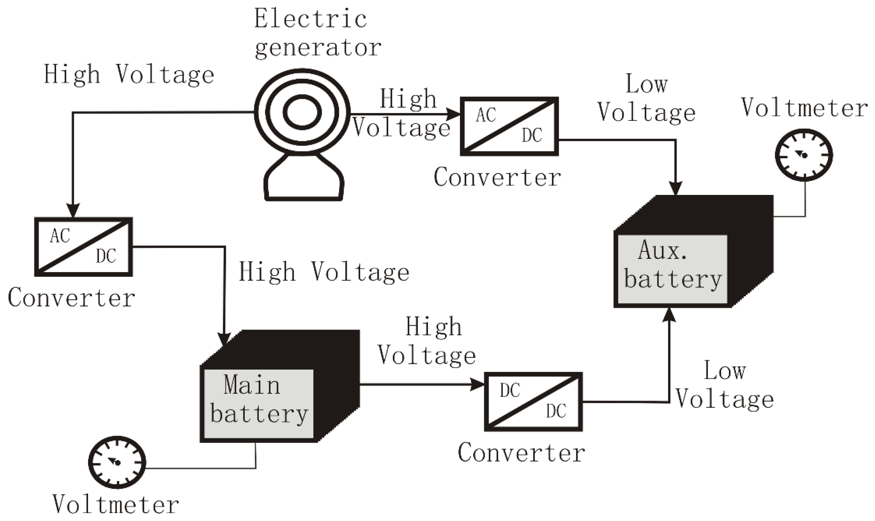
We base the development of the control system on the premise that it is feasible in current urban driving conditions to recharge the auxiliary battery using the recovery energy from the regenerative braking. Two options arise when injecting current into the auxiliary battery; this can be achieved directly from the electric generator or via the main battery (see
Figure 1).
The operational mode of the proposed control system applies a methodological process focused on obtaining high efficiency in the charging of the two batteries, managing the energy obtained from the regenerative braking in an optimum mode.
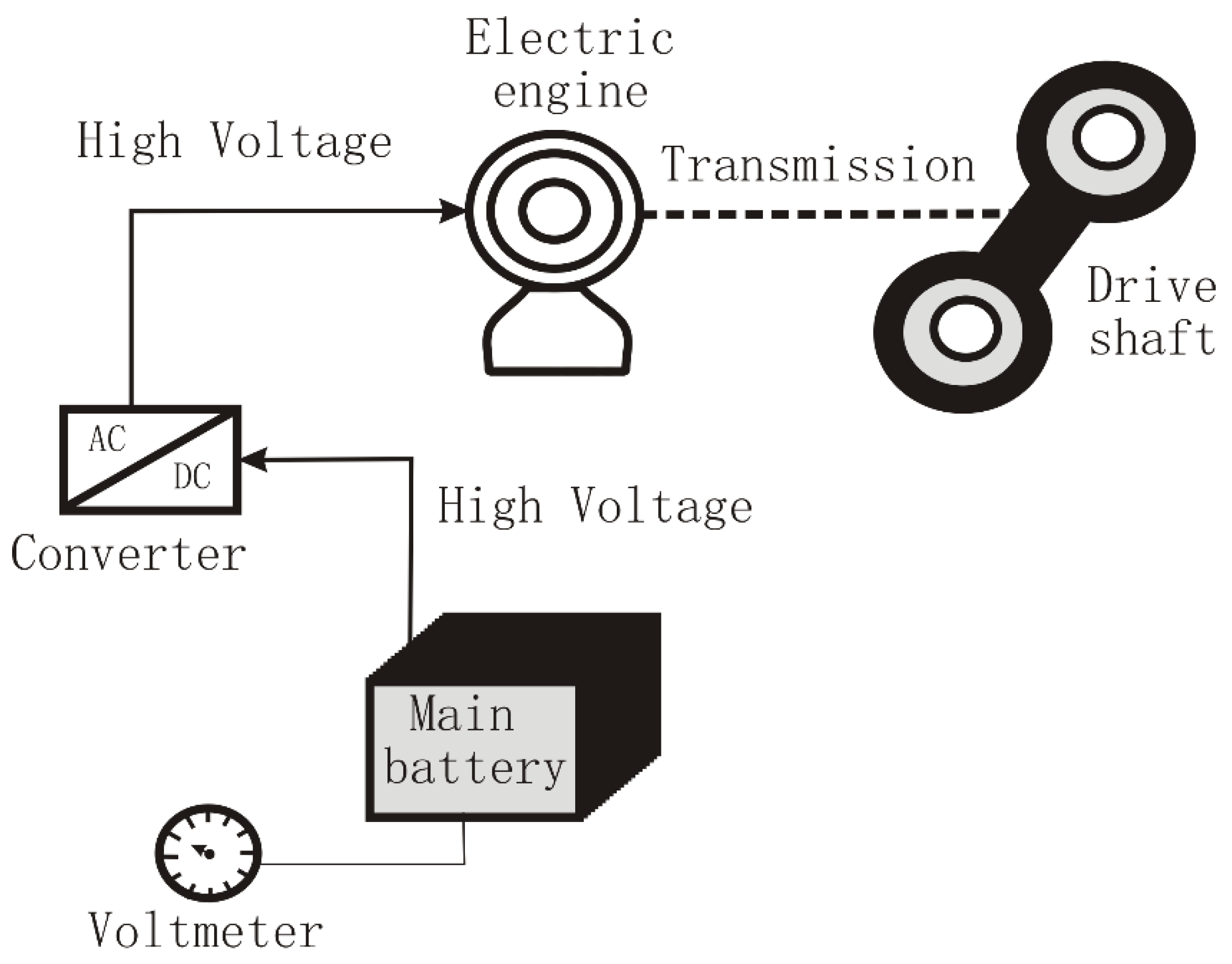
In current conditions, the electric generator in
Figure 1 plays the role of an electric engine transferring power from the main battery to the wheels (
Figure 2), and it reverses to generate electric current during the regenerative braking or energy recovery in the deceleration process.
The voltmeters, each attached to one of the two batteries, control the state of charge (
SOC); since the voltage evolution of a lithium-ion battery is linear during the discharge or charge process, the
SOC is determined by applying the following equation:
where
V is the battery voltage and sub-indexes
i,
o, and
off account for the current, full charge, and discharge states.
Two different situations arise in daily driving operations. The electric engine acts as a generator or as a motor; the former case corresponds to the regenerative braking process, and the latter to the power supply to the driver shaft. Depending on the state of charge of the main and auxiliary battery, the current flows through different sections of the electric circuits represented in
Figure 1 and
Figure 2.
The proposed control system decides to drive the current flow to the main or auxiliary battery, or both, as a function of specific criteria based on the state of charge of the two batteries and the working condition of the electric engine, motor, or generator.
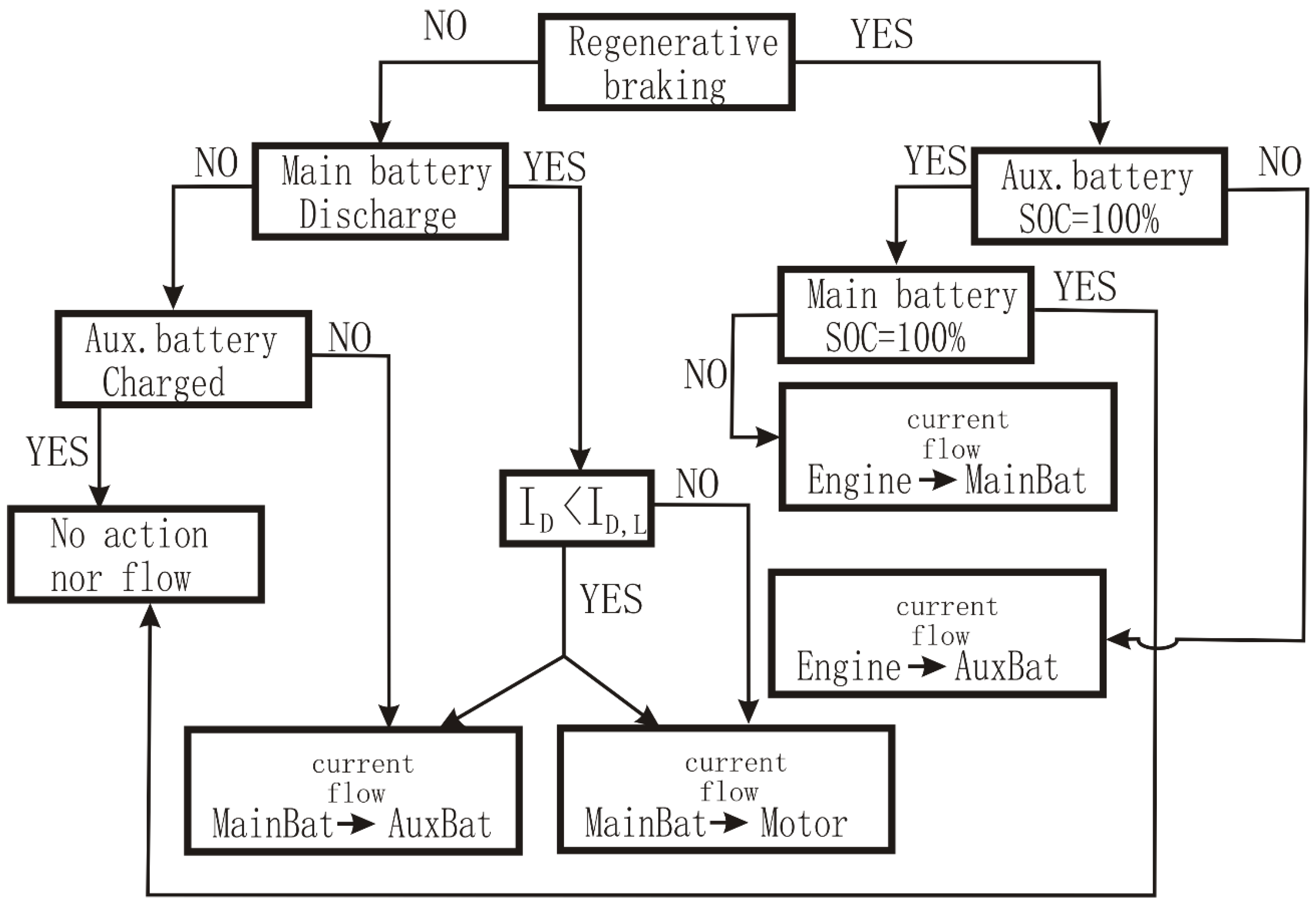
Figure 3 shows the flow chart on which the ruling algorithm of the control system works.
Analyzing the flowchart of the control system, we notice that in regenerative braking mode, the electric engine, which plays the role of the generator, charges the auxiliary battery in direct mode, as shown in
Figure 1, without going through the main battery.
Control System Protocol
The control system operates according to the following protocol shown in the flow chart of
Figure 3:
- 1.
The system detects if the regenerative braking is operating.
- a.
If not, the control system verifies if the main battery discharges.
- i.
If not, the control system checks the state of the charge of the auxiliary battery.
- ii.
No further action is required if auxiliary battery is 100% charged.
- iii.
If auxiliary battery is not 100% charged, the control system closes the relay, and the main battery charges the auxiliary one.
- b.
If the main battery discharges, the control system determines the protection limit current, applying Equation (23).
- i.
The control system compares the drawn current from the main battery with the protection limit current.
- ii.
If drawn current exceeds the protection limit value, the control system closes the relay and blocks the current flow from main to auxiliary battery; if not, the main battery recharges the auxiliary one.
- 2.
If regenerative braking is activated,
- a.
The control system checks the state of charge of the auxiliary battery.
- b.
If the SOC is lower than 100%, the recovered energy from the regenerative braking first recharges the auxiliary battery.
- c.
If auxiliary battery is 100% charged, the control system checks the state of charge of the main battery.
- d.
If the SOC of the main battery is 100%, no further action is required.
- e.
If the SOC of the main battery does not reach 100%, the recovered energy from regenerative braking recharges it once the auxiliary battery is 100% charged.
The proposed configuration suffers from pros and cons which influence the performance of the charging process. The bypassing of the main battery forces the use of a high-to-low AC/DC converter, which operates at a limited efficiency because of the voltage drop. The conversion of alternate to continuous current also reduces the efficiency, but much less than the voltage drop.
3.2. Ancillary Equipment Load
To determine the ancillary equipment energy load, we identify its composing elements. Although these elements depend on the car manufacturer and vehicle class, we can include the following as a regular set-up list (
Table 1). Because the energy consumption of the auxiliary elements of an electric car depends on the driver’s habits, we must use a reference value from statistical analysis [
11].
We have divided the ancillary equipment into two classes, immediate and retarded, depending on the possibility of delaying their use to the most suitable moment. Indeed, we cannot postpone the operation of the so-called immediate equipment when their use is required; however, we may delay the use of the retarded equipment to the moment when the energy demand from the auxiliary battery optimizes the process.
The list of the current power consumption of the above-mentioned ancillary equipment is shown in
Table 2. We use the mean power value for every element as a reference for global energy use.
All the ancillary equipment does not operate simultaneously; therefore, we should consider the simultaneity in use when calculating the power demand. The following equation provides a simple way of determining the required energy for a given time.
where
P is the power of any ancillary element,
t is the operating time, and
f is the simultaneity factor.
Since the simultaneity factor is hard to determine, we replace it with the average daily time of use; therefore, Equation (8) converts into:
where <
t>
i is the average daily time of use.
Applying values from
Table 2 to Equation (9), we have:
Combining Equations (5) and (8):
Applying values from previous studies [
16,
17], we have:
4. Simulation
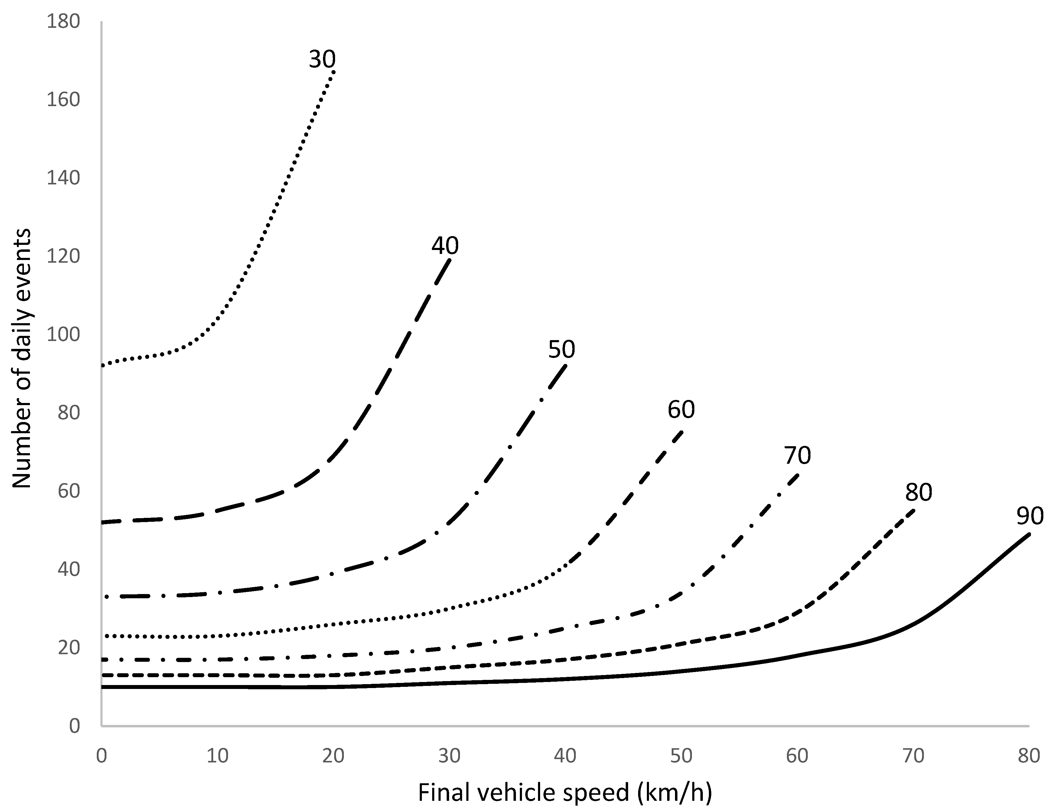
We can represent the vehicle speed reduction from an initial set-up velocity to a final one by applying Equation (13). We show the results of the simulation in
Figure 4.
Figure 4 shows the corresponding number of daily events where a reduction in the vehicle speed should occur if we intend to recharge the auxiliary battery from the recovering energy. Numbers of the different curves correspond to the initial set-up velocity of the vehicle. We have considered a maximum vehicle speed of 90 km/h, a current value in modern cities, even for peripheral circulation.
We observe that the corresponding number of daily events where a reduction in the vehicle speed should occur increases with a lowering of the initial set-up velocity. The number increases dramatically for low initial speed; for low vehicle speed, the auxiliary battery recharge from the recovering energy is not feasible.
The number of vehicle speed reductions heavily depends on the speed itself, since driving conditions tend to be more fluid at higher speeds, thus requiring a lower number of velocity reduction events. We use a previous study of the subject based on statistical analysis [
18] to establish the reference number of daily times of vehicle speed reduction.
Table 3 shows the results of the study.
The required final vehicle speed is the value that fulfills the condition of recharging the auxiliary battery from the recovered energy.
We notice the required final vehicle speed follows a defined pattern, expressed by the following relation:
Equation (14) determines the final speed the vehicle has to reach regularly during a braking process from a given initial speed to satisfy the condition of recharging the auxiliary battery from regenerative braking.
If the vehicle completely stops:
It is evident that the solution of Equation (15) is not compatible with current driving conditions if we intend to recover the required energy to recharge the auxiliary battery in a single braking process; however, if we consider the minimum value of the daily average number of braking events, shown in
Table 3 as a reference for the times that the vehicle completely stops in a daily journey, we obtain:
This result means that we must stop the vehicle 13 times a day from an initial speed of 42.2 km/h to fulfill the condition of recharging the auxiliary battery from the regenerative braking. The number of braking stops and the initial vehicle speed before stopping are compatible with driving conditions in an urban journey.
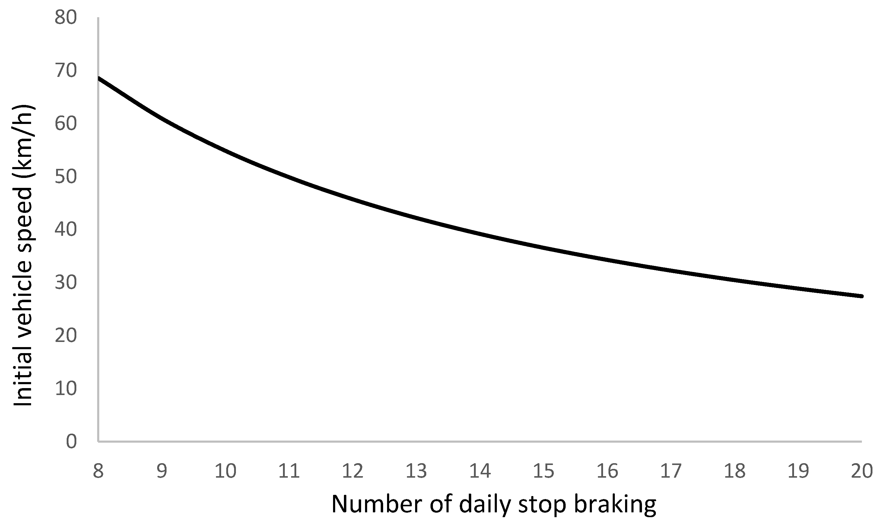
The condition imposed in Equation (16) changes with the number of braking stops, as seen in
Figure 5, considering the driving conditions within city limits.
The evolution of the initial vehicle speed with the number of daily stop-braking follows a pattern:
nstb represents the number of daily braking stops.
Considering reference values [
19,
20,
21,
22], the efficiency of an AC/DC converter can reach up to 95.1%, although the current value operates between 90% and 95%. In indirect charging, using the main battery as a power source, the recharge of the auxiliary battery involves two steps: the charge transfer from the generator to the main battery and the transfer from this latter one to the auxiliary battery. The first step requires a high-voltage AC/DC converter, which operates at efficiencies of 98%; the second step requires a high-to-low DC/DC converter whose efficiency may reach up to 98%, although the current operational value is in the range of 90% to 96% [
23,
24,
25,
26,
27]. The second step considers the efficiency of charge/discharge cycling of the main battery, which in the case of lithium-ion cells is between 95% and 98% [
28,
29,
30].
Using the average value of the efficiency interval for the converters and for the charge/discharge battery cycling, we obtain:
We observe that direct charging improves the efficiency of the process by 4.5%.
If regenerative braking is deactivated, the only option to charge the auxiliary battery is from the main one; in such a case, the protocol for the proposed control system includes a condition to preserve the energy capacity of the main battery. Indeed, the capacity of lithium-ion batteries lowers with the increase of the discharge rate according to the following factor [
31]:
where the discharge time,
tD, depends on the discharge current:
where
Cr and
Cn are the current and nominal capacity of the battery, and
ID is the discharge current.
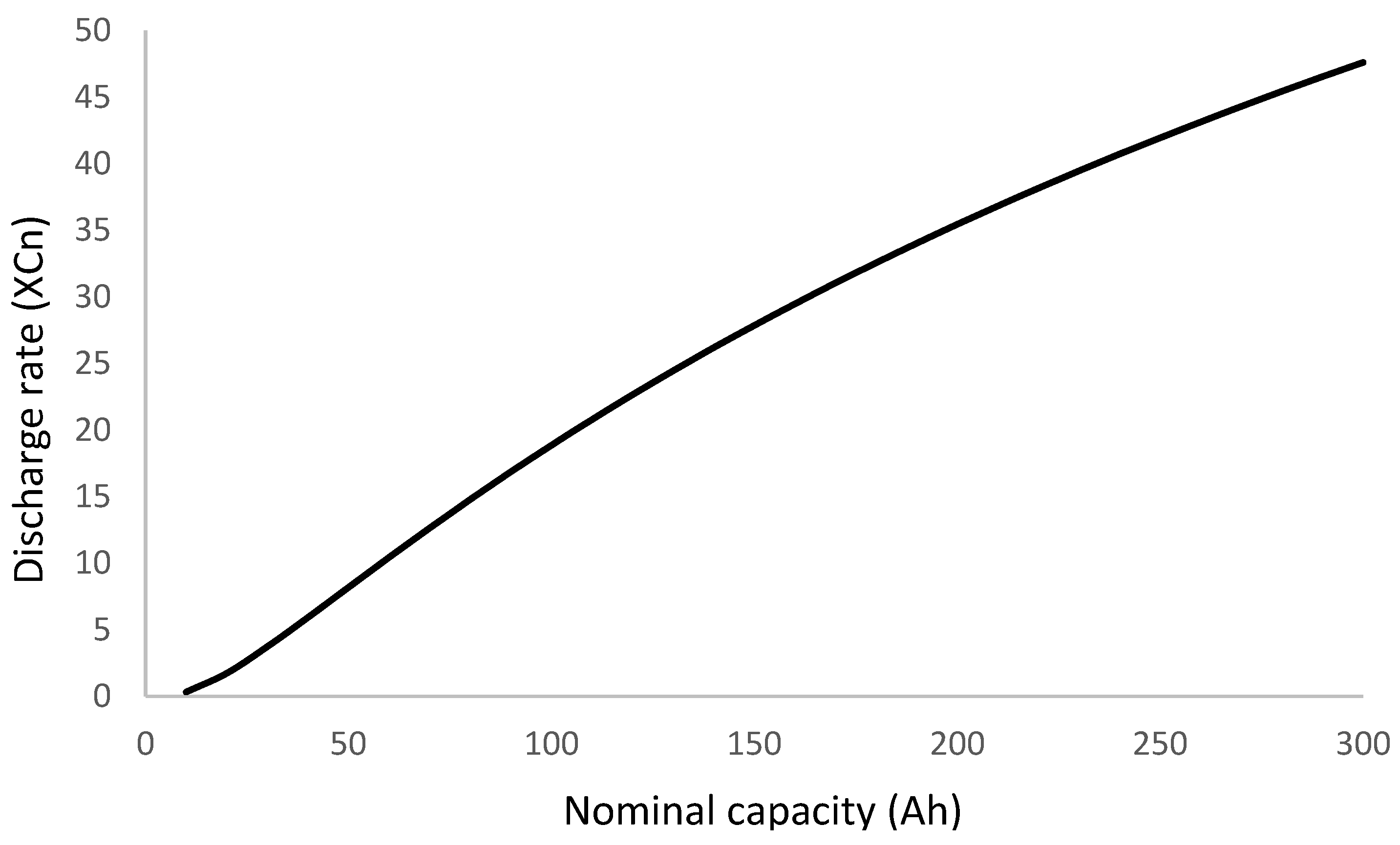
We have set up a maximum capacity reduction of 5% because of the discharge rate required to maintain the energy capacity of the battery within limits; therefore:
Equation (21) shows the limit for the discharge current beyond which the reduction of the battery capacity overpasses the threshold of 5%. This condition imposes a maximum discharge rate, represented in
Figure 6 as a function of the battery’s nominal capacity.
The evolution of the discharge rate adjusts to a polynomial function of the second degree:
Expressing the discharge current in terms of the discharge rate:
The parameter ID,L is called the protection limit current.
If the current drawn from the main battery when the regenerative braking is not active exceeds the
ID,L value, the control system protocol (
Figure 5) forces the system to block the recharge of the auxiliary battery, which charges when the regenerative braking is activated.
5. Materials
To verify the validity of the proposed control system and the developed simulation, we built an electric circuit reproducing the layout of the battery charging shown in
Figure 1. The experimental prototype is a scale model of the current version of electric vehicles. We use as a reference an electric engine operating at 400 V with a high voltage battery of 50 kWh. Our model consists of a lithium-ion battery of 920 Wh at 29.4 V; therefore, we operate with a scale factor of 200 (
fξ = 54.35) for the battery energy capacity, and a scale factor of 25 (
fV = 13.61) for the battery voltage.
Using the values for the prototype and model, we calculate the battery capacity:
Sub-indexes p and m account for the prototype and model.
The capacity ratio from prototype to model defines the scale factor for the battery capacity:
The auxiliary battery in our model is a lithium-ion one of 12 V with a capacity of 2.5 Ah. Comparing these values with the standard auxiliary battery that equips an electric vehicle [
32], we obtain
Table 4:
The values from
Table 4 show the following voltage, capacity, and energy factor for the auxiliary battery.
We observe that the energy factor for the main and auxiliary battery fulfills Ohm’s law.
Assuming the model works in the same driving conditions as the prototype, we design the control system of the model to stand for an equivalent operational current applying the conversion factor; mathematically:
Applying values from
Table 4, the maximum intensity of the modeled electric circuit is:
Current driving conditions, however, never operate at maximum intensity; therefore, we introduce a factor of 0.8, which results in a maximum operational intensity for the modeled circuit of 5 A.
Model Circuit Layout
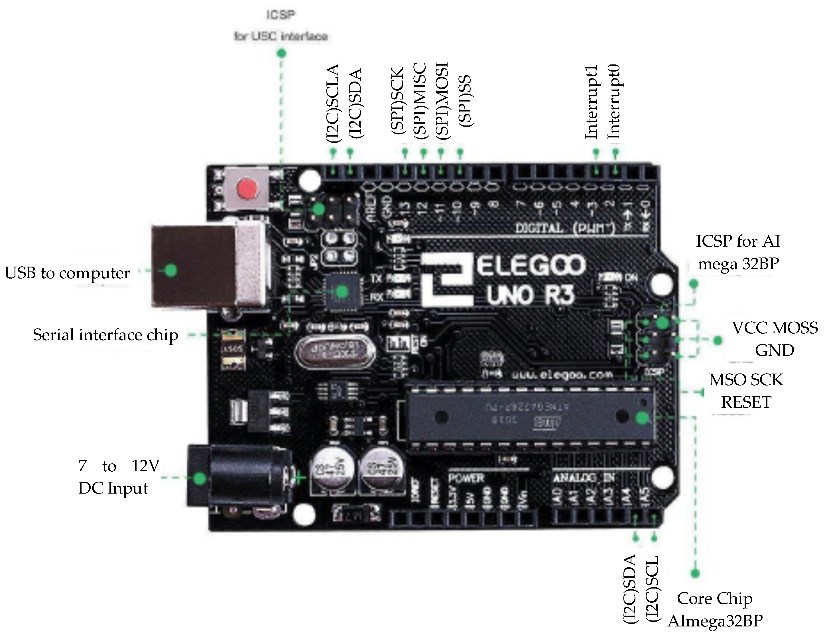
The electronic assembly is orchestrated and managed by an Elegoo module, which operates under the Arduino structure. This module can be found in many fields, like electronics, automatism, motor control, and others, because it is easy to use. The Elegoo module used in this assembly is the UNO R3 (
Figure 7).
This module allows us to control the power delivered by our two batteries and simulate our simplified path.
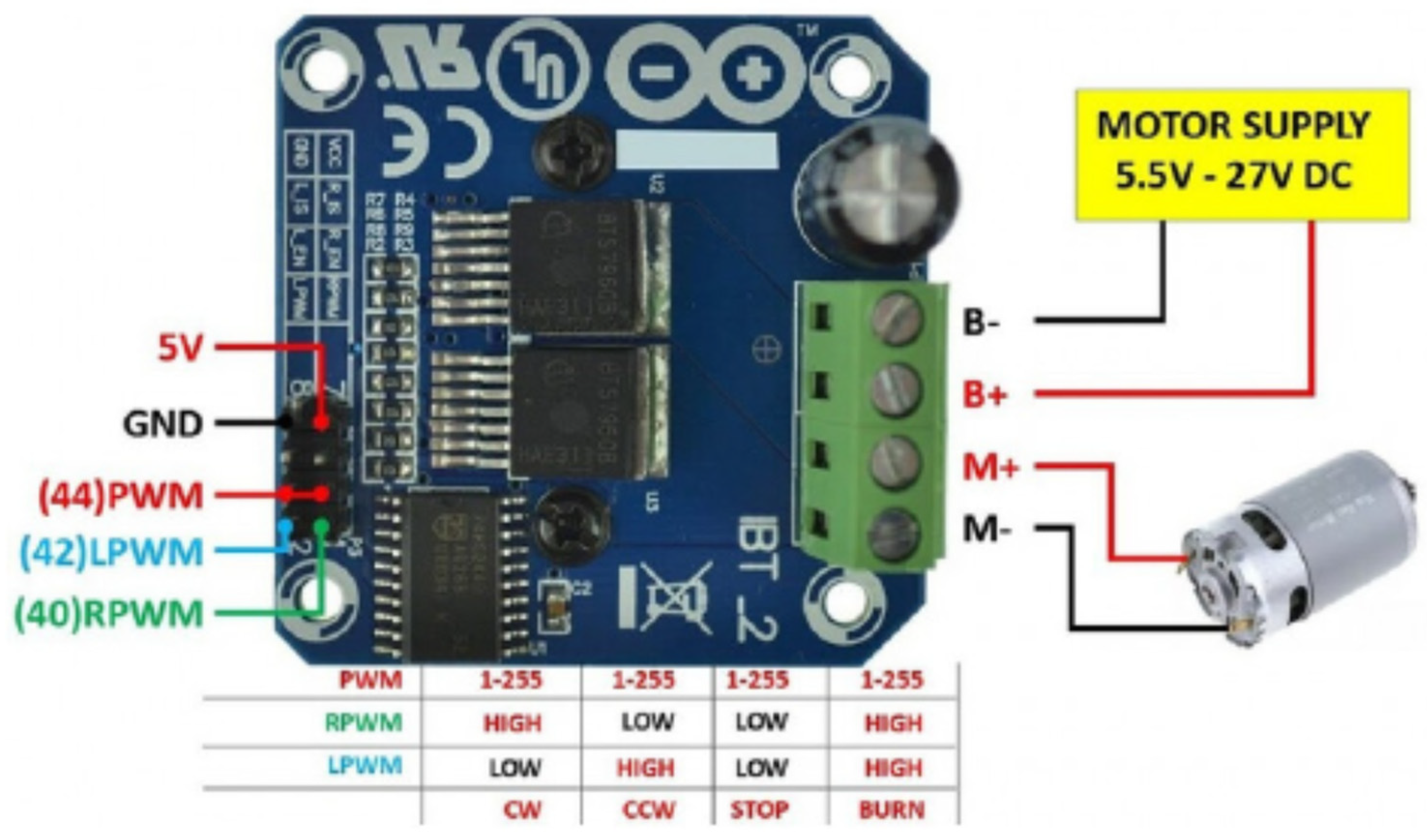
To control the electric motor, we use a BTS7960 driver (
Figure 8). This driver is capable of managing a maximum intensity of 43 A at a supply voltage in the range of 6 to 27 V; since the maximum delivered intensity by the modeled auxiliary battery is 30 A, and the operational voltage of the battery falls in the working range of the driver, the selected driver is a good option for the control system.
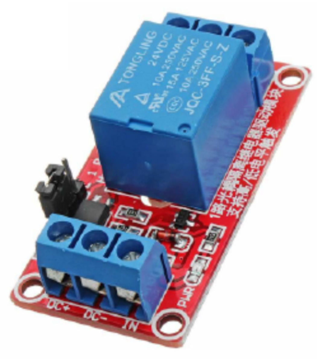
The relay module that controls the current flow from the electric generator to the battery is a JQC-3FF-S-Z type (
Figure 9).
The Elegoo Arduino board controls the relay. It is located between an external power source that acts as an electric generator and the battery. It opens or closes the circuit depending on the electric signal associated with the dissipated power. If the power is negative, the relay closes, and the current flow is interrupted. However, if the power is positive, the relay opens, and the current flows via the BTS7960 driver.
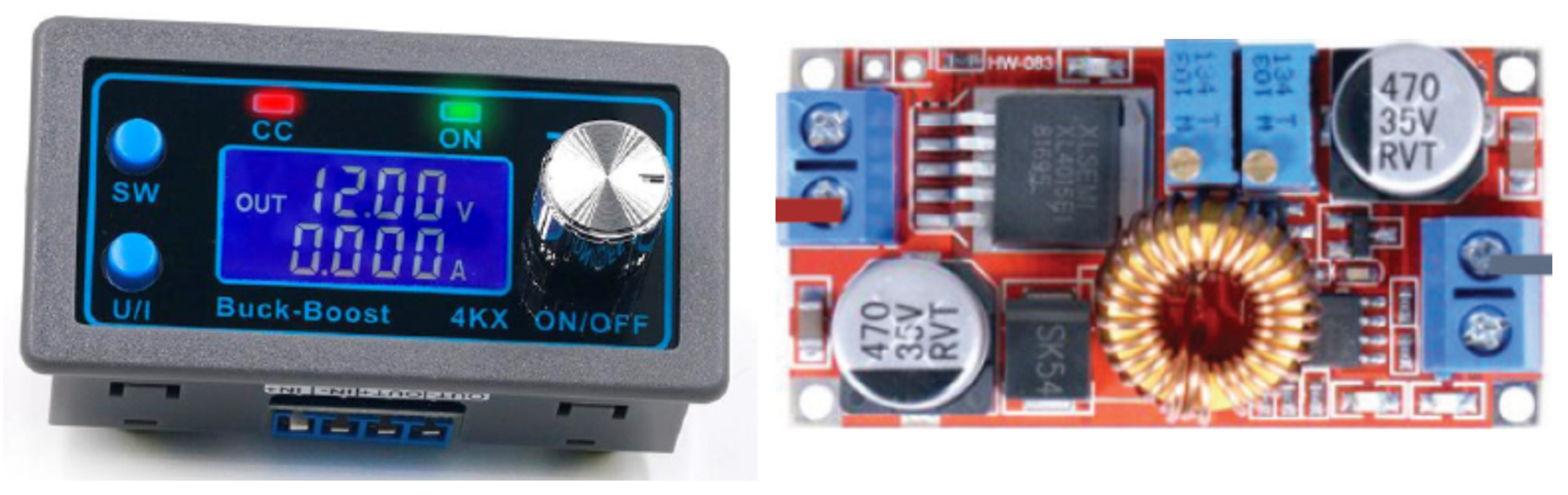
To convert the high to low voltage from the main to the auxiliary battery, we use a DC/DC converter like the one shown in
Figure 10. We use a similar device for converting AC to DC from an electric generator to a main or auxiliary battery (
Figure 10).
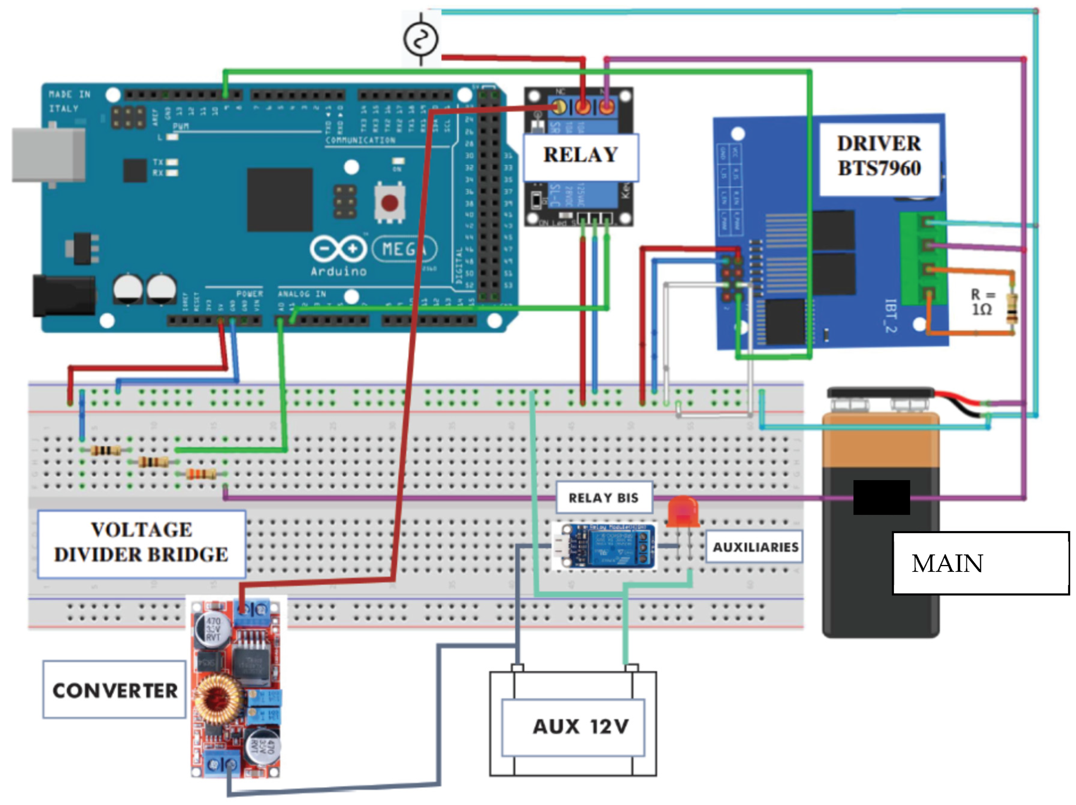
All the elements are mounted on the control system board (
Figure 11).
To run the tests, we adjust the external power to the corresponding values of city driving conditions, scaling the values according to the power factor. We also adjust the current and voltage regulating the converter units through the control software. Power data, voltage, and current come from a database of previous simulation tests and works to evaluate the performance of batteries in electric vehicles [
34,
35,
36] or to analyze dual battery block configurations [
37]. Data also come from the evaluation of the driving range of electric vehicles [
38], the performance of electric vehicle motors [
39], or the analysis of kinetic energy recovery [
40].
Experimental Implementation
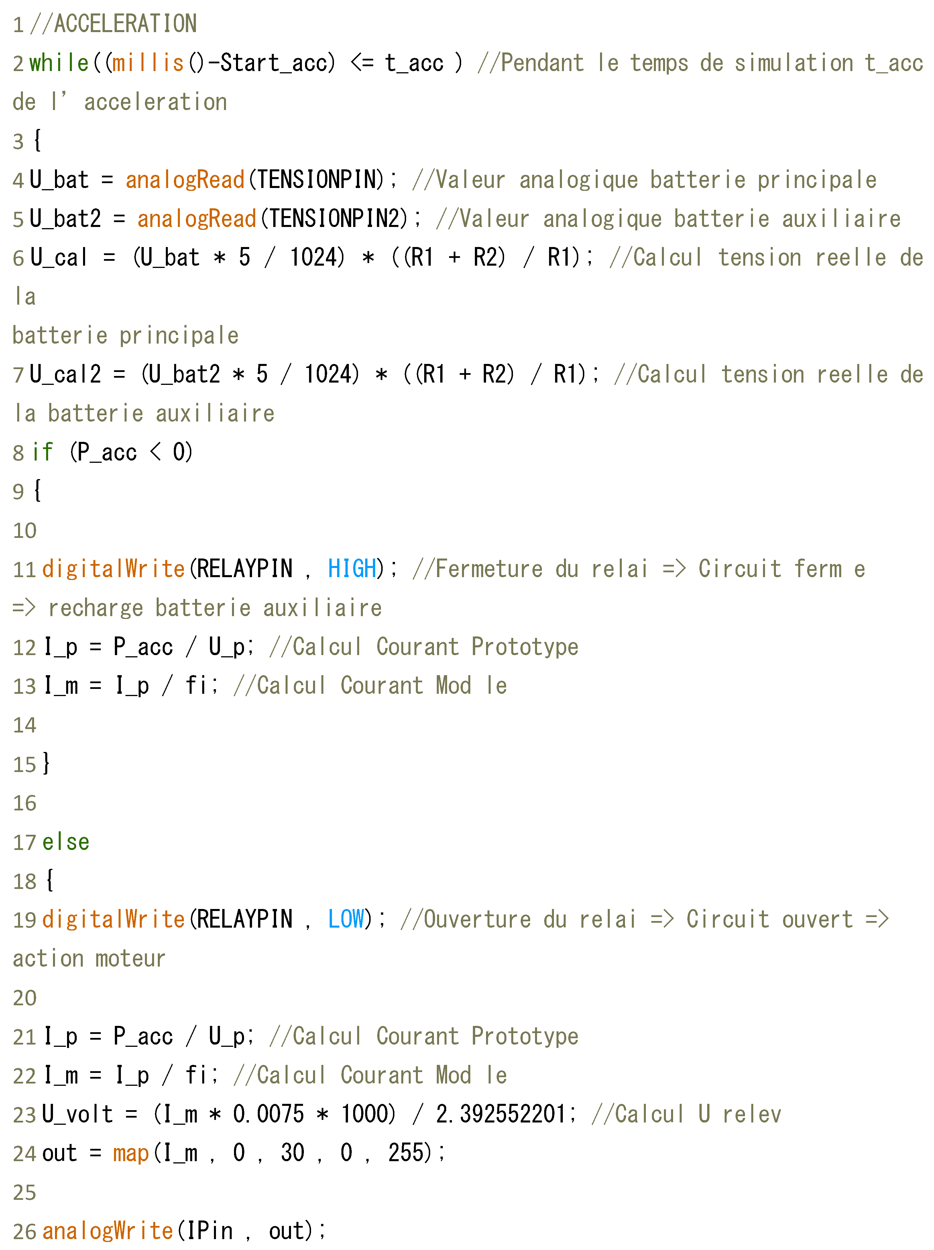
We start the process using Arduino code that allows the protocol to set up the initial conditions of the experimental implementation (
Figure 12); the protocol is based on previous work [
41].
Table 5 summarizes the initial conditions of the implementation.
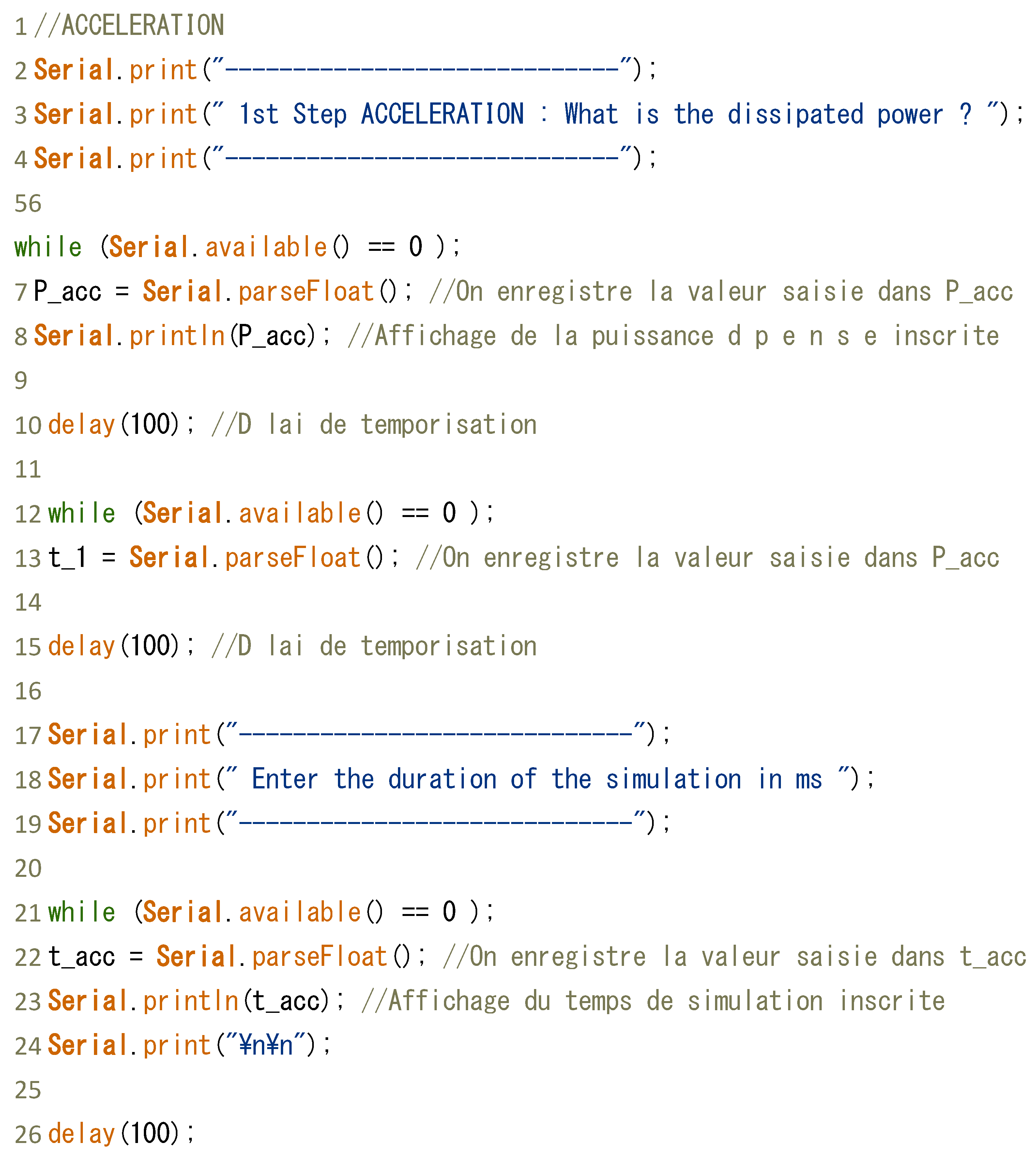
Using the power values shown in
Table 5, we simulate our journey, step by step, entering the intensity values (
Table 6); therefore, we can calculate the voltage at the terminals of the two batteries, applying the following code (
Figure 13).
We adapted the intensity values for the experimental simulation from the ones used in previous studies for developing control systems for electric vehicles devoted to enlarging the driving range [
42,
43].
6. Results
Our experiment operates on extracting the current from the battery, which is controlled by the action of the BTS driver and controlled by the PWM signal. This current is monitored by an ammeter and controlled by a 7.5 mΩ resistor to avoid a high current.
Table 7 shows the reading of the voltage values at the terminals of the two batteries.
We notice a high matching between theoretical values and experimental results for the acceleration process, higher than 98%. In the case of normal driving, the matching is slightly lower, at only 94%. According to these results, we consider that the simulation reflects rather faithfully the driving conditions in the current situation.
During the simulation we control the state of charge of the two batteries.
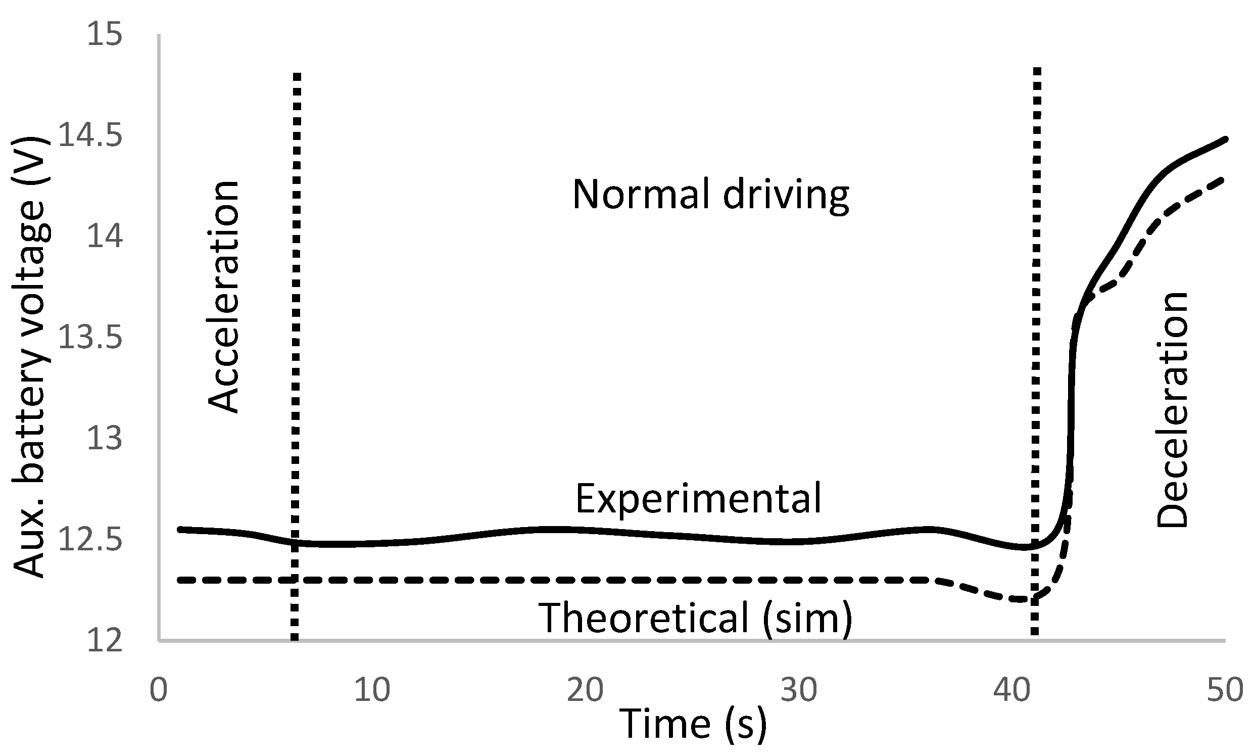
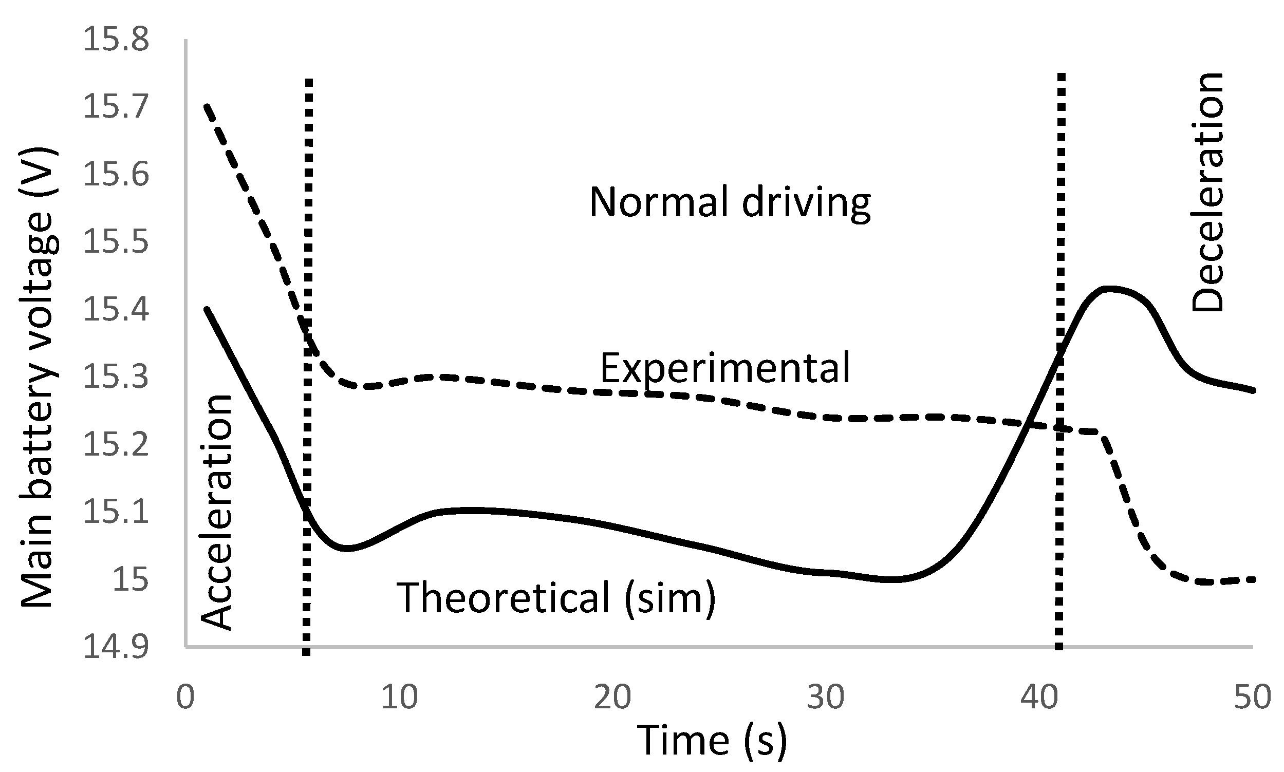
Figure 14 and
Figure 15 show the results for the auxiliary and main battery.
The dashed line corresponds to the theoretical predictions of the simulation algorithm; the solid line represents the experimental values in the simulation tests. We notice the high correspondence between simulation and experiments, proving the validity of the proposed model. The matching of theoretical to experimental values is of 98.4% accuracy for the two batteries.
We observe how the auxiliary battery voltage remains constant during the acceleration and normal driving stages, since the electric vehicle operates only with the main battery in these two processes. Nevertheless, during the deceleration, we use the recovery energy to charge the auxiliary battery.
In the case of the main battery, we observe a drastic voltage drop at the acceleration stage due to the high required power; during normal driving, the main battery supplies power to the vehicle to compensate for drag and friction forces, and the battery voltage lowers. Finally, during the deceleration, the main battery voltage decays because the recovery energy is not high enough to charge the auxiliary battery.
We observe a good match between experimental data and simulation results in the evolution of the auxiliary battery voltage, with a slight gap at the acceleration and normal driving mode (constant speed). The gap does not represent a significant deviation in the battery voltage determination, around 0.8%, which we attribute to the uncertainties in determining the battery voltage by the measuring unit (1%). We check that the gap deviation is lower than the experimental band error, which justifies the existing gap.
The gap vanishment at the deceleration mode corresponds to a transition state where time at simulation and the experimental test is not evolving; thus, the values match. This situation is attributed to a mathematical singularity in the battery voltage determination during simulation since the voltage determination responds to a step function during the transition state. For the experimental tests, the voltage suffers a sudden increase for the near null transient time; therefore, the gap disappears. The reader can notice that for the non-transient state, the gap maintains the differential value observed for the acceleration and normal driving mode.
Regarding the main battery, the gap between experimental data and simulation results is identical, 0.8%, for the acceleration and normal driving mode. The same justification for the auxiliary battery voltage evolution applies.
We observe, however, that the simulation results and experimental data show a diverging trend during the last normal driving and first deceleration periods; we attribute this behavior to the recovery energy system, which operates with a time delay due to capacitive effects. On the other hand, the difference in battery voltage between simulation prediction and experimental results is of 0.9%, within the uncertainty band error.
7. Conclusions
The paper introduces a new type of lithium battery dual block that can power a vehicle and its ancillary equipment. The device is operated by a control system that is specifically designed to allow for independent operation of both the main power battery and the auxiliary one.
We design a control system to improve energy management in electric vehicles. The control system aims to recharge the main and auxiliary batteries with efficiency.
The proposed control system represents an innovation in the area of battery electric vehicle power management with a dual battery block, contributing to optimizing the performance of the power battery. As a result, the driving range of an electric vehicle can be increased because of a more effective use of the available energy.
The control system prioritizes the charge of the auxiliary battery in cases where the regenerative braking is activated. To this goal, the control system uses a charging process that skips the main battery and directly charges the auxiliary one from the electric generator. This process improves the efficiency of the auxiliary battery charge by 4.5%.
The protocol for the control system allows for protecting the main battery from capacity reduction in case of a high discharge rate when the regenerative braking is not activated. In this case, the control system prioritizes the main battery by blocking the recharge of the auxiliary one and postponing this latter process until the regenerative braking is activated.
Auxiliary battery charging from regenerative braking is only viable for cumulative processes, either from braking or speed reduction. The number of required cumulative processes depends on the speed reduction and the vehicle speed. Auxiliary battery charging is not achievable for low vehicle speeds, even with cumulative processes.
The experimental simulation proves the method’s validity with a close agreement between theoretical values and experimental results. The accuracy of the simulation is higher than 98%.
The tested prototype of the control system reproduces the situation in current driving conditions, showing how the main and auxiliary battery voltage evolves when the electric vehicle submits to acceleration, normal driving, or deceleration processes.


