Abstract
Polymer bonded magnets based on thermoplastics are economically produced by the injection molding process for applications in sensor and drive technology. Especially the lack of orientation in the edge layer, as well as the chemical resistance and the creep behavior limit the possible implementations of thermoplastic based polymer bonded magnets. However, thermoset based polymer bonded magnets have the opportunity to expand the applications by complying with the demands of the chemical industry or pump systems through to improved chemical and thermal resistance, viscosity and creep behavior of thermosets. This paper investigates the influence of hard magnetic particles on the flow and curing behavior of highly filled thermoset compounds based on an epoxy resin. The basic understanding of the behavior of those highly filled hard magnetic thermoset systems is essential for the fabrication of polymer bonded magnets based on thermosets in the injection molding process. It is shown that several factors like the crystal structure, the particle shape and size, as well as the thermal conductivity and the adherence between filler and matrix influence the flow and curing behavior of highly filled thermoset compounds based on epoxy resin. However, these influencing factors can be applied to any filler system with respect to a high filler amount in a thermoset compound, as they are based on the material behavior of particles. Further, the impact of the flow and curing behavior on the magnetic properties of polymer bonded magnets based on thermosets is shown. With that, the correlation between material based factors and magnetic properties within thermosets are portrayed.
1. Introduction
Typical fields for polymer bonded magnets are the sensor and drive technology. In sensor systems, polymer bonded magnets are normally a signal transducer for example to detect linear and rotatory motion and position in combination with a Hall sensor [1] or a magnetoresistive sensor [2]. Further, the spin wave effect can be used to process signals even in distributed systems with high time parallelism [3]. Especially in the automotive industry, many applications in sensor systems can be found, for example controlling the motion of the wiper or sunroof and registering the torque and rotation angle for steering systems [4]. The main application within the drive technology is the magnetic excitation of synchronous or direct current (DC) machines [2]. Those applications are as yet mainly realized by thermoplastic based polymer bonded magnets as this type of magnet can be fabricated by injection molding and with that, the processing is suitable for series production.
Injection molded magnets are mainly based on a thermoplastic matrix and have a filler content of about 60% of the volume. In some cases, filler content of more than 65% of the volume can be reached [1]. Higher filled polymers can normally not be processed by injection molding [5]. Thermoset based polymer bonded magnets are primarily manufactured in a pressing process [6]. Within the pressing process, a high packing density of up to 84% of the volume can be reached [7]. Due to a higher percentage of filler within the matrix of a sample fabricated in the pressing process, higher magnetic properties are realized [8]. The filler can make up 85% of the volume in the pressing process [1]. The filler content determines the maximum of the magnetic properties a sample can have. As this content is less in injection molded samples these parts have lower magnetic properties than pressed samples. The benefits of the injection molding process are the freedom of design of the samples [8] and the size accuracy [1] even for small and thin shaped samples [9]. This accuracy is realized due to the number of fillers and thus less shrinkage [10]. Furthermore, a functional integration, for example, by inserting metallic components is possible [11]. Thermosets enable a higher chemical permanence and thermal resistance, as well as lower creep tendency in respect to thermoplastics. Furthermore, a thermoset molten mass reveals a significantly lower viscosity, which enables fillers more likely to move within the molten mass in the cavity [12]. Therefore, thermoset based polymer bonded magnets may have the opportunity to expand the applications for polymer bonded magnets for example by realizing the demands of cooling water pumps or the chemical industry. Especially magnetic excitation of synchronous or DC machines has a larger application field if chemical permanence and thermal resistance allow the implementation in positions near the engine, pumps engaged with water or oil and within the chemical industry. It has to be taken into account that as yet thermosets are mainly used in a pressing process. Therefore, the application of polymer bonded magnets can only be extended if the thermoset based magnets can be produced in an injection molding process and the benefits of this fabrication method are used.
In 2012, 59% of the worldwide utilized neodymium-iron-boron (NdFeB) were applied in drive technologies like electric motors in the industry, e-mobility and wind energy. Within these applications only 6% were fabricated by polymer bonded magnets, due to the fact that so far the technology for manufacturing polymer bonded magnets in driving applications is nearly unknown [13]. First investigations for these applications based on thermoplastics within the research project FKZ 03VNE2052D show the possibility of implementing polymer bonded magnets by injection molding in synchronous reluctance motors with respect to limited chemical permanence and thermal resistance [14]. This reveals the potential that is not used within the application of drive technology for thermoset based polymer bonded magnets until now.
1.1. Magnetic Properties
Magnetic properties are based on the smallest magnetic unit within a solid and can be described by the magnetic moment of a single electron and its rotation around its axis also named spin [15]. Based on the smallest magnetic unit there are four different structural order systems with preferential direction by which the magnetic properties of materials are distinguished [16]. In the case of ferromagnetic materials, all magnetic moments are oriented parallel and reach the highest total magnetic moment. They can be divided into hard and soft magnets. As hard magnets have a characteristic high resistance against demagnetization, these materials are also called permanent magnets [17]. Polymer bonded magnets consist of a matrix material (thermoplastic, thermoset or elastomer) and a filler (e.g., strontium-ferrite-oxide SrFeO or neodymium-iron-boron NdFeB) [18]. The filler material has different magnetic properties and geometries as well as particle sizes. For example, SrFeO particles exhibit a hexagonal geometry with a particle size of 1–10 µm and NdFeB a plate like structure with a particle size of 100–400 µm. The resistance against demagnetization of NdFeB is two to three times higher than the resistance of SrFeO [19]. The filler material can have isotropic or anisotropic magnetic properties [20]. The magnetic moments in isotropic filler particles are orientated randomly. Therefore, samples with isotropic filler do not have a preferential direction regarding the magnetic properties. The magnetic properties of anisotropic fillers are the best parallel to the preferential direction and the worst vertical to this direction as the magnetic moments are orientated in a certain tack. Samples with anisotropic fillers reach for the remanence BR about 85% of the saturation flux density BS depending on the filler content and the quality of the production process. The remanence BR of samples with isotropic fillers obtain only 50% of BS [8]. It has to be mentioned that the orientation of fillers with a preferential direction can only be taken place if the fillers are mobile and exhibit a magnetic moment [8]. Taking into account that thermosets reveal a lower viscosity within the molten mass in the cavity relative to thermoplastics, the possibility of orientation is more likely in a thermoset based polymer bonded magnet especially in the edge zone where rapid cooling takes place for thermoplastics. Magnetic properties can be further increased by mixing different particle sizes in that way that smaller particles can fill the gaps between the bigger ones [21].
The magnetic moments of the anisotropic filler particles have to be oriented and magnetized within production. The magnetization can also be done afterward, for example, using impulse magnetization [5]. For anisotropic particles, the magnetic field strength influences the rate of the orientated particles and the possible remanence BR after magnetization until BS. Therefore, a certain magnetic field strength depending on the filler material is needed to guarantee a full orientation of anisotropic filler particles and the greatest possible magnetic properties [22]. The orientation and magnetization in the process is realized by a permanent magnet or an electromagnetic coil and a current through this conductor [5]. High magnetic properties can be reached by increasing the filler content. However, the orientation of the magnetic moments can be disturbed by particle interactions, which are more likely to occur if the filler content is high.
1.2. Injection Molding
The behavior of and the temperature setting for thermoplastics and thermosets in the injection molding process are completely different. Thermoplastics require a high temperature for plastification and are injected into the low-temperature cavity [23]. Thus, rapid cooling takes place in the edge zone where the viscosity increases fast and prematurely. This temperature profile leads to a relatively high viscosity in the cavity, which impedes the orientation of the magnetic filler particles [24]. Thermosets undergo a change of the chemical structure within the injection molding process as the polymer chains are cross-linked due to high temperatures. As this process shall take place in the cavity and is activated by temperature, plastification has to take place at a low-temperature level. Thermosets are injected into a high-temperature cavity so that the cross-linking process can take place. Nevertheless, the viscosity in the cavity is first reduced due to the high temperature [25]. It is assumed that this low viscosity within the cavity can be used to orientate filler materials even in the edge zone as the tool surface and with that, the magnetic field is displayed precisely. The time-dependent process of cross-linking increases the viscosity again. The reduction and the increase of the viscosity are both temperature driven and contrary [25].
1.3. Flow Behavior and Reaction Kinetics of Thermosets
A number of papers regarding the influence of filler material on the flow behavior and reaction kinetic of thermosets have been published [26,27,28,29]. It is well known, that the fillers affect the cure and rheological behavior of epoxy resins for example by improving the thermal conductivity or modifying the chemistry of the cure [30]. Regarding the research of [26], the filler influences the reaction rate below 100 °C using a silica filler with a mean diameter of 10 µm in an epoxy resin with a filler content of 30 vol.-%. Due to physical interactions between the filler and the resin the reaction rate is increased with respect to the temperature. The fillers increase the free energy of the system and the gelation is more enabled [31].
The influence of filler content, filler size and filler geometry on the thermal conductivity of a compound based on an epoxy resin has been investigated in [32]. It was shown, that the thermal conductivity increases with the filler content especially with more than 50 vol.-% as the content of the particles is high enough to generate a meshwork of particles increasing the thermal conductivity of the whole sample. Further, the thermal conductivity can be improved within the processing of thermosets due to a high amount of cuboid particles with a big particle [32]. With respect to the results of [33], the flow behavior can be improved by reducing the filler content and increasing the size. Further, the cycle time can be reduced by an increasing filler content and reduced filler size, whereas the filler size has less impact on both factors.
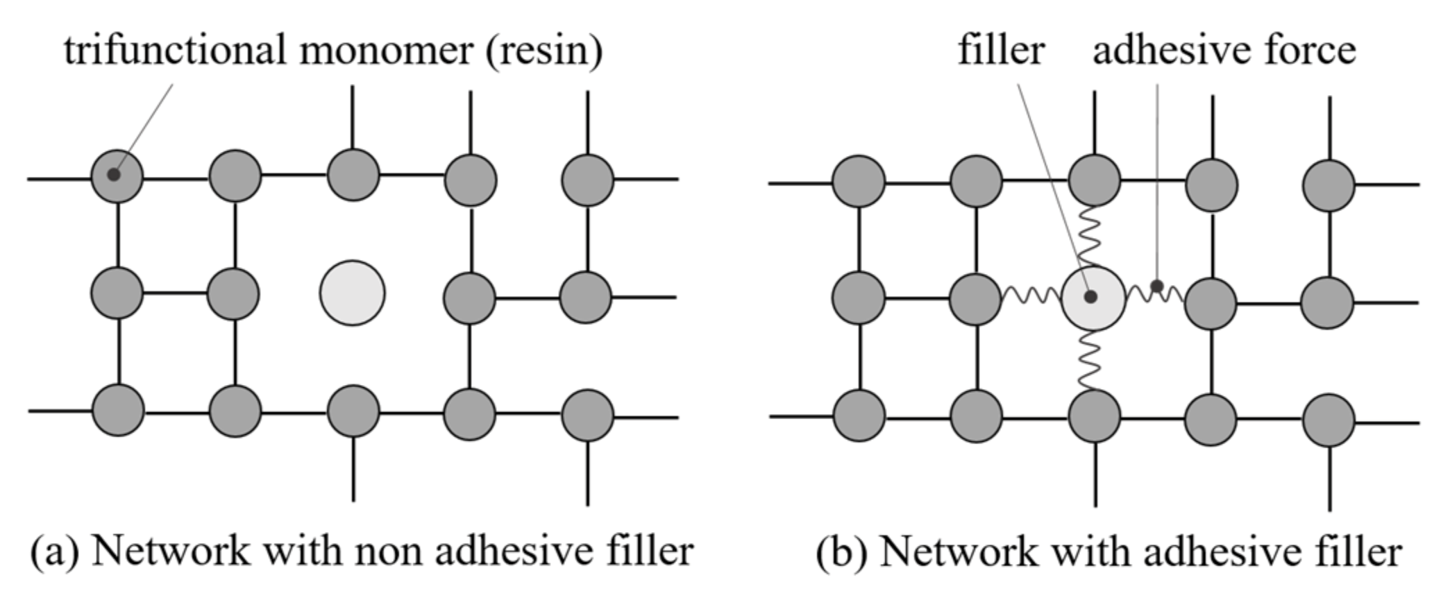
With respect to [34], the gelation is a function of the molecular network structure, which means that the influence of the fillers depends on the adhesive properties of the particles. If the particles portray no adhesive force to the resin, they act like holes in the network and reduce the gelation due to interruptions of the pathway. This is schematically shown in Figure 1. The trifunctional monomers of the resin join and build a tridimensional network during the curing. This network building can be interrupted by fillers as shown in Figure 1a with no adhesive force to the resin leading to interrupted pathways of the network structure. If adhesive forces are present, the fillers enable the network structure to build around the fillers integrating them in the curing process. This is portrayed in Figure 1b [34].
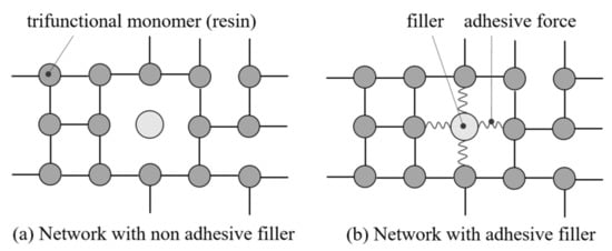
Figure 1.
The network structure of filler and resin with (a) no adhesive force and (b) adhesive force between filler and resin in parts: after [34].
However, most of this research is based on a relatively low filler content of less than 10 wt.-% or highly filled systems with respect to thermoset compounds with up to 50 wt.-% whereby the results cannot be transferred automatically to highly filled systems in terms of polymer bonded magnets with up to 90 wt.-%. The impact of hard magnetic fillers in thermosets is not systematically studied. In [35] it was shown that spherical particles with a particle size of 45 µm increase the flowability and curing velocity relative to the plate-like fillers with a size of 100 µm. However, the influence of the structure and the size was not distinguished and with that, a precise insight of the influencing factors regarding hard magnetic fillers in a thermoset are not given.
1.4. Aim of the Paper
The aim of this paper is to investigate the influence of hard magnetic particles on the flow and curing behavior of highly filled thermoset compounds based on an epoxy resin. In detail, the impact of filler content, filler size and isotropy shall be analyzed for the particles SrFeO and NdFeB for an isotropic and anisotropic type. The basic understanding of the behavior of those highly filled hard magnetic thermoset systems is essential for the fabrication of polymer bonded magnets based on thermosets. Further, the impact and with that, the flow and curing behavior of highly filled thermosets is correlated with the magnetic properties of compounds based on the hard magnetic fillers within an epoxy resin.
2. Materials and Methods
2.1. Material
The experiments were conducted with the hard magnetic particles of anisotropic SrFeO and both isotropic and anisotropic NdFeB. For SrFeO the anisotropic type was OP 71 (Dowa Holdings Co., Ltd., Tokyo, Japan). For NdFeB the isotropic type was MQB+ (Magnetquench GmbH, Tübingen, Germany) and the anisotropic type was MQA 38-14 (Magnetquench GmbH, Tübingen, Germany). Table 1 presents the mean particle size and the density of the filler material regarding the manufacturer specifications. Note that the mean particle size of SrFeO is much lower than that of NdFeB and that the isotropic type of NdFeB has a higher mean particle size relative to the anisotropic type. Further, the thermal conductivity and heat capacity based on the manufacturer specifications are shown in Table 1 as both factors, as well as the density are important filler properties with respect to the flow and curing process. The thermal conductivity and the heat capacity are material but not isotropy dependent.

Table 1.
Specification of filler material including mean particle size and density (manufacturer specifications).
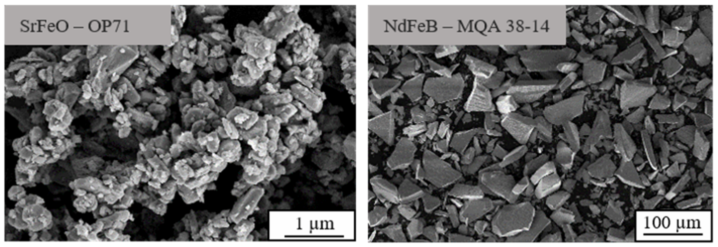
Figure 2 depicts the geometry of the anisotropic filler material SrFeO (hexagonal) and NdFeB (plate like) using a scanning electron microscope (Gemini Ultra-Plus; manufacturer: Carl Zeiss AG, Oberkochen, Germany). As the geometry is filler dependent but mainly isotropy independent, only the anisotropic particles are shown.
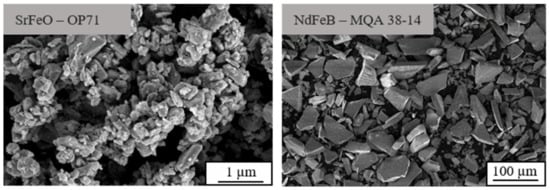
Figure 2.
Particle geometry of anisotropic SrFeO and NdFeB using a scanning electron microscope.
For both filler types, the amount of the filler in the compound was varied between 40 and 70 vol.-% in intervals of 10.
The matrix material was an epoxy resin (EP) mixture named Epoxidur 245/1 (Raschig GmbH, Ludwigshafen, Germany). It is a premixed black powder with epoxy resin, hardener, catalyst and some carbon black pigments. The exact composition of the mixture is a business secret, and therefore, confidential.
2.2. Fabrication of the Test Specimens
2.2.1. Preparation for Material Characterization
The compounds were produced manually by mixing the two components in the dry state at room temperature. With respect to the required amount of material, which is necessary for the testing method, the proportion of the filler and the matrix material was weighted. After adding the exact amount of both components into a vessel, a bar was used to mix the compound manually. The monitoring of a homogeneous and sufficient mixing took only place by optical control.
2.2.2. Preparation for Magnetic Characterization
To realize the investigations of the magnetic properties, test samples were needed. Therefore, the manual mixed compound was fabricated using a twin-screw extruder (Kraus Maffei Berstorff ZSE 25Ax45D, KrausMaffei Group, Munich, Germany) with a screw diameter of 25 mm and speed of 80 rotations per minute. The nozzle temperature was set at 90 °C to ensure that the material does not cure within the extruder. The test samples were produced path controlled by a Krauss Maffei KM 80-380 CX DUR/03 injection molding machine (KrausMaffei Group, Munich, Germany) with a screw diameter of 30 mm. The processing parameters were set as shown in Table 2 without an outer magnetic flux density in the cavity. Within the dual cavity of the test samples of plates with the dimension of 60 × 60 × 2 [mm3], a magnetic field was not integrated to evaluate the magnetic properties realized by the injection molding process with respect to the flow and curing behavior but without the impact of an outer magnetic field. The holding pressure was adopted relative to the filler content. The heating time of 300 s is long with respect to a common injection molding process. Due to the optimization of the compound recipe regarding the viscosity, the gel time is yet too long to reach economic standards.
Table 2.
Processing parameters of injection molding to fabricate test samples (EP 245/1 with 40 to 70 vol.-% hard magnetic filler).
2.3. Characterization
2.3.1. Particle Size Distribution
The particle size distribution of the filler materials was measured using an optical camera with static image analysis (Morphology G3s, Malvern Panalytical GmbH, Kassel, Germany). The volume of the measured filler samples was 5 mm3. In one measurement up to 80,000 particles were counted.
2.3.2. Differential Scanning Calorimetry (DSC) following DIN EN ISO 11357
To investigate the temperature dependent reaction kinetic of the compounds a differential scanning calorimetry (DSC Q100, TA Instruments, New Castle, Delaware, USA) was used. Samples of about 5 mg were placed into the DSC aluminum pans and heated with a constant rate of 10 °C per minute from 0 °C to 240 °C. After reaching 240 °C and holding the temperature isothermal for 0.5 min the temperature was reduced to 0 °C with a constant rate of 40 °C per minute. After another isothermal state lasting 5 min, the second heating with a constant rate of 20 °C per minute up to 250 °C was carried out. The experiment was done in a nitrogen atmosphere with a flow rate of 50 mL per minute. The slow heating rate in the first cycle was needed as higher rates led to evaporation of components, and therefore, a distortion of the results. A number of parameters based on the DSC measurement were evaluated. Figure 3 depicts the general route of a DSC measurement for the first and second heating cycles for thermoset materials. The curing reaction is exothermal and can be characterized by the starting point ① with the corresponding temperature T1 and time t1 and the ending point ② with T2 and t2. The total time period of the curing process is Δttotal. In the first heating cycle, the OnSet-temperature TOS marks the beginning of the characteristic peak of the curing with the time tOS. The specific enthalpy of the curing process, as well as the amounts of the specific enthalpy before and after reaching TOS with respect to the time period between t1 and tOS (time period before reaching OnSet-point Δt1;OS) and tOS and t2 (time period after reaching OnSet-point ΔtOS;2), classifies the curing process further [36].
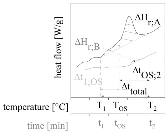
Figure 3.
General rout of a DSC measurement in the first and second heating cycle with characteristic parameters for the evaluation.
The degree of curing Σcuring can be calculated considering Equation (1) where ΔHr;A is the total specific enthalpy in the first heating cycle and ΔHr;B is the total specific enthalpy in the second heating cycle. It is valid that the curing degree of 90% is sufficient for reaching proper mechanical and physical properties [37].
2.3.3. Flow Behavior of Powdered Compound
To characterize the flow behavior of the compound after mixing without temperature impact, the bulk density (following DIN EN ISO 60) and the flowability (following DIN EN ISO 6186) are measured. For the calculation of the bulk density, a certain amount of the material is filled into a funnel, which is closed by a valve. The valve is moved away so that the material can pass into a cylindrical cavity. This cavity has a defined volume VB of 100 mL. After filling the cavity the excessive material has to be removed to calculate the mass mB of the material in the cavity. The bulk density ρB indicates the cohesive force between the particles in the bulk. A low bulk density corresponds to strong cohesive forces. Further, cohesive material has the opportunity to break bulk bridges due to pitching which leads to compression and new orientation of the particles. The bulk density ρB can be calculated in consideration of Equation (2) [38].
To measure the flowability a defined mass mB of 150 g is filled into a funnel, which is again closed by a valve. After removing the valve, the time which is needed by the compound to pass the funnel is measured and defined as flowability.
2.3.4. Specific Heat Capacity c and Thermal Conductivity λ of Pure Filler Material and Compounds
To evaluate the important particle properties regarding the temperature control and input on the flow and curing behavior, the specific heat capacity c was determined for 25 °C using the C80 calorimeter (type: 3D-Calvet calorimeter; TA Instruments, New Castle, Delaware, USA). The specific heat capacity was measured for the pure filler material as well as the compounds in order to analyze the impact of filler and matrix material on the parameter. Further, the mixing rule was used to control the impact of the components relative to the proportion of them. The mixing rule can be defined with respect to Equation (3) where cx represents the specific heat capacity of the components or the compound and mx reveals the mass percentage of the components.
The thermal conductivity λ of the filler material was determined at 23 °C using extrapolation of measurements of the thermal conductivity λ based on compounds where plate-like samples was analyzed in a HotDisk (C3 Prozess- und Analysetechnik GmbH, Haar, Germany). The extrapolation was based on the Lewis-Nielsen equation, as portrayed in detail in [32].
The specific heat capacity c as well as the thermal conductivity λ are temperature dependent. Nevertheless, the measured parameters can be used to evaluate the impact of the fillers on the temperature during curing and its impact, as well as to verify the validity of the manufacturer specifications (Table 1).
2.3.5. Flow and Curing Behavior
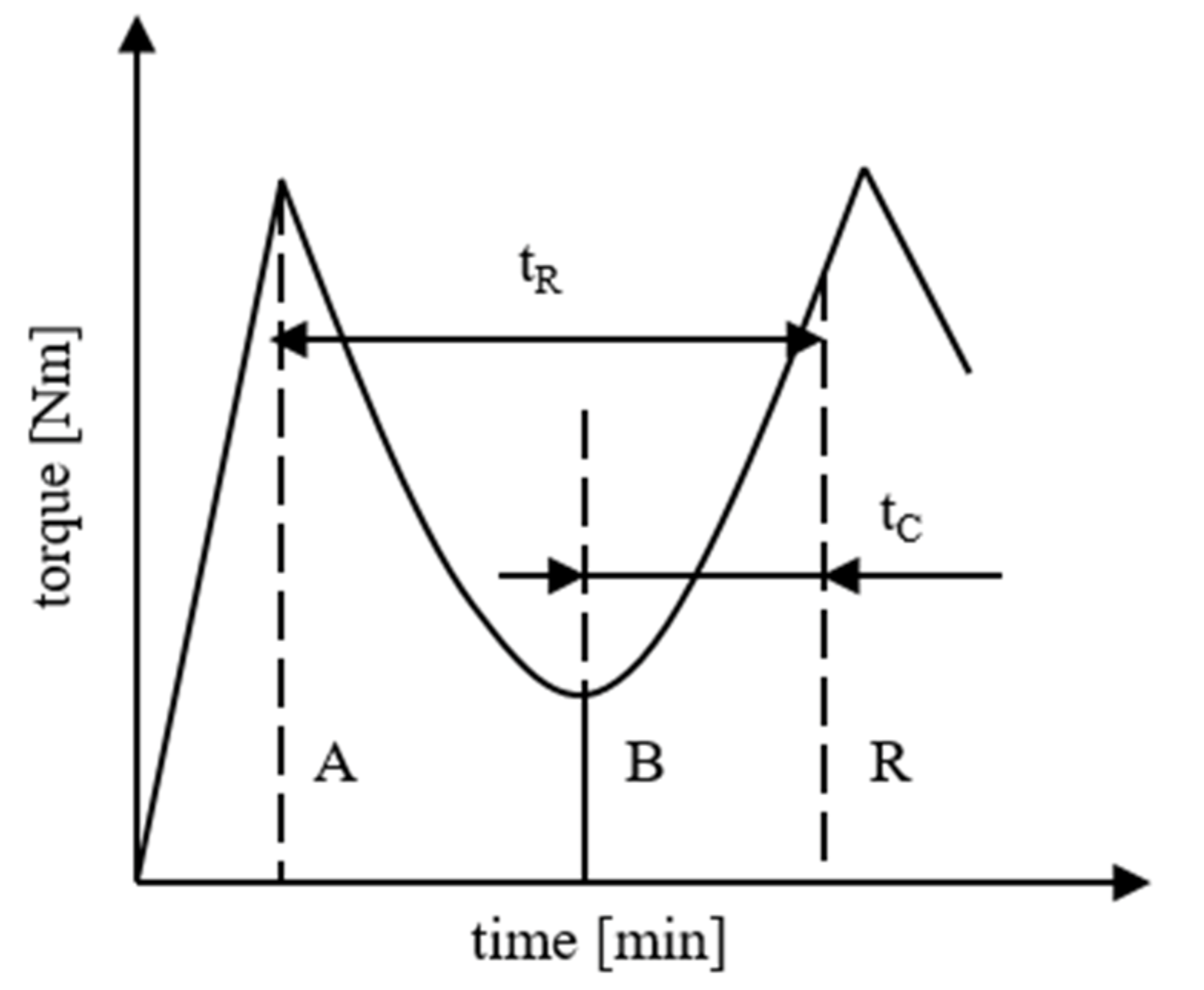
To characterize the flow and hardening behavior of the compound a measuring mixer (Mixer MB30, Brabender GmbH & Co. KG, Duisburg, Germany) was used. The measuring mixer consists of two kneaders that rotate in the cavity with a constant rotation speed of 30 rpm. The cavity exhibits a constant temperature of 110 °C. This value is chosen based on experience to reach a sufficient curing speed and change of viscosity. The temperature in the cavity is slightly higher than usually chosen for the matrix material in the injection molding process. However, this temperature realizes almost the minimum of the viscosity in the pure epoxy resin. Further, the rotation speed is very low as in the injection molding process shear rates of 103 to 104 are present [12]. Nevertheless, shearing takes place in the measuring mixer due to specially designed kneaders [39]. It can be assumed that the viscosity is reduced about two decades through the shear rate and increased about one decade through the temperature in the injection molding process. With that, the characterization of the compound in the measuring mixer can be compared with the behavior of the material in the injection molding process with respect to the temperature and the shear rate. The characterization does not display the actual temperature profile and shear rate in the injection molding process. However, it realizes a decent approximation for the evaluation of the general material behavior.
The material is loaded into the cavity while the kneaders rotate so that the specially shaped kneaders can homogenize the compound. The sample size is held constant at 18.75 cm3, which is 75 vol.-% of the whole cavity. To maintain the constant rotation speed the torque has to be adjusted with respect to the viscosity of the material. The required torque is measured. After the first peak A at the end of the loading phase, the torque is reduced due to the high temperature in the cavity until the minimum B. Due to cross-linking processes, the viscosity increases again reaching the second peak point X. After this point the torque drops again as the material cannot be deformed viscous and is, therefore, chopped in small pieces. To analyze the flow behavior of the compounds the minimum B is evaluated. A low value for B indicates good flowability. Further, the time between the minimum B and 80% of the crosslinking process (reaction R) is detected as the curing time tC and the time between the first peak A and the reaction R is recorded as the reaction time tR. A high value for tC indicates a slow change in the viscosity, and therefore, a gently curing speed. This results in a long cycle time, which is uneconomic. A high value for tR suggests a stable process but also a wide process window. Again, a wide process window extends the cycle time. It has to be taken into account that a small process window increases the economy but calls for an exact process setting. Figure 4 depicts the ideal route of the torque while analyzing the flow and hardening behavior of a thermoset in the measuring mixer. The characteristic points for the evaluation are also shown in Figure 4.

Figure 4.
Ideal route of the torque and characteristic points for analyzing the flow and hardening behavior of thermosets in the measuring mixer.
2.3.6. Scanning Electron Microscope
To investigate the particle distribution and position as well as the linking between the filler and the matrix material a scanning electron microscope (Gemini Ultra-Plus; manufacturer: Carl Zeiss AG, Oberkochen, Germany) was used. Samples were taken out of the small pieces after the measuring mixer, as these pieces were chopped under process conditions. The samples were cracked manually to analyze the fractured surface. A 10 nm layer of spray gold was placed on top of the samples. The pictures were taken with a working distance of 9.0 to 13.8 mm and an acceleration voltage of 10 kV.
2.3.7. Magnetic Properties
The magnetic properties and more precisely the remanence BR, the coercivity HcB and the maximal energy product (BH)max are evaluated by measuring the hysteresis loop using a permagraph (type: C-300, Magnet-Physik Dr. Steingroever GmbH, Cologne, Germany). The permagraph applies a magnetic field strength H from outside onto the samples to magnetize and demagnetize the material. A sensor gathers the magnetic flux density B or the magnetic polarization relative to magnetic field strength H. The magnetic field is applied perpendicular to the circular interface of the sample. To realize a full magnetization of the filler particles a pulse magnetizer (type: Im-12220-U-MA-C, Magnet-Physik Dr. Steingroever GmbH, Cologne, Germany) and a magnetic device (type: MV D30X30 mm F-TC, Magnet-Physik Dr. Steingroever GmbH, Cologne, Germany) were used before each measurement. The capacitor bank of the pulse magnetizer was charged by a transformer to 1.9 kV. This is sufficient to fully magnetize the filler particles. The stored energy was discharged by a thyristor within the coil of the magnetic device. All measurements were conducted at room temperature.
3. Results and Discussion
3.1. Particle Size Distribution
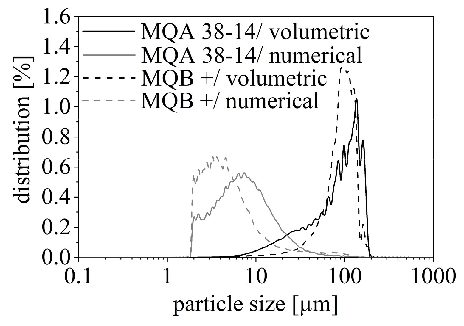
The particle size distribution shows the volumetric and numerical distribution of the particles and gives a good overview of which particle sizes are present in the different filler materials. Figure 5 depicts the numerical and volumetric particle size distribution for the NdFeB filler with two different isotropies. Both have a high amount of small particles in the range of 2 to 20 µm and only a little amount of great particles. Taking the numerical distribution into account, the maximum particle size is reached with 6.97 µm for MQA 38-14 and with 4.30 µm for MQB+. This contradicts the mean particle size given in Table 1 as the listed mean sizes above 100 µm are only marginally present. Further, Figure 5 reveals only a slight difference in the two isotropy types of NdFeB. However, the isotropic type MQB+ has a minimal smaller range of particle sizes.
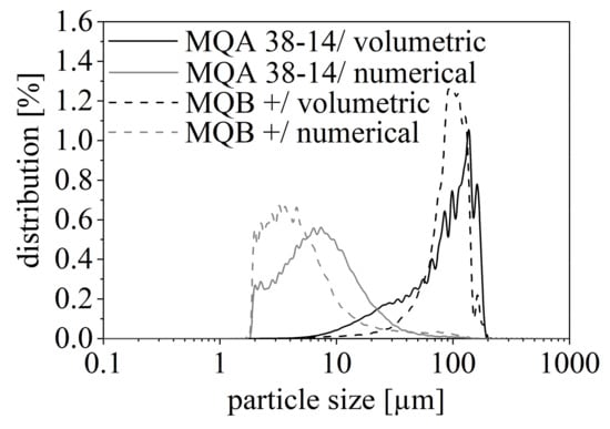
Figure 5.
Numerical and volumetric particle size distribution of isotropic (MQB+) and anisotropic (MQA 38-14) NdFeB.
SrFeO depicts a similar behavior as the numerical distribution is mainly between 1 and 10 µm and its maximum is reached with 3.2 µm. Therefore, both SrFeO and NdFeB have a similar particle size in the range of 1 µm to 20 µm. Due to this resemblance, Figure 5 only depicts the distribution of NdFeB. The difference between the two filler particles is a small amount of greater particles in the range of 100 µm for NdFeB. Both SrFeO and NdFeB might have a small number of further particles with sizes less than 1 µm, which cannot be depicted due to the maximal resolution of the analysis technique with 1 µm.
The investigation in the particle size distributions illustrates that not only the mean particle size but also the numerical distribution are important to know. This clarifies the difference between filler materials with respect to their particle size. Besides the mean particle size, the numerical distribution of the filler size emphasizes the particle size and is likely to appear with respect to a high amount of this extent. This value defines the behavior of the filler, for example with regard to the tendency to build agglomerates or the possibility to fill even smaller gaps within matrix material or between greater filler particles.
3.2. Differential Scanning Calorimetry (DSC)
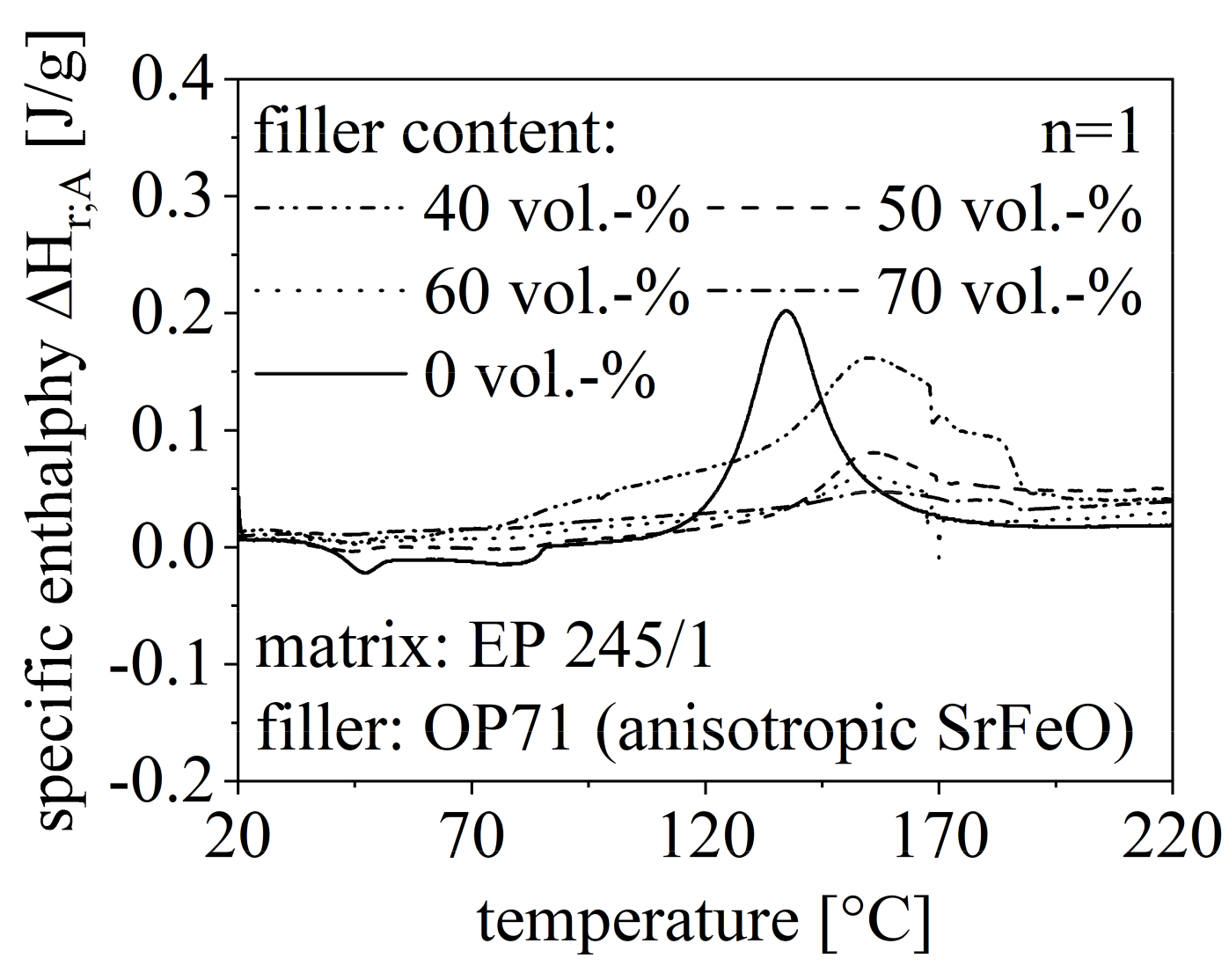
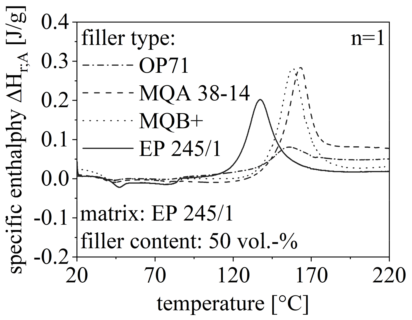
The route of the DSC measurements with respect to different filler content is shown in Figure 6 for the anisotropic SrFeO (OP71) exemplary. Further, the route for different filler types is depicted in Figure 7 for a constant filler grade of 50 vol.-%. Both routes in Figure 6 and Figure 7 are compared to the DSC measurement of pure EP. The specific enthalpy needed for the curing process is reduced with increasing filler content and is less for filler content greater than 50 vol.-% compared to the pure EP. Further, TOS increases with a higher filler amount. The specific enthalpy of NdFeB in the curing process is similar to pure EP but significantly higher relative to SrFeO. Further, the isotropic and the anisotropic NdFeB show similar behavior in terms of TOS and ΔHr;A.
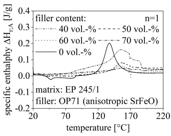
Figure 6.
Route of DSC measurement in the first heating cycle relative to the filler amount between 40 and 70 vol.-% of anisotropic SrFeO (OP71) and pure EP.
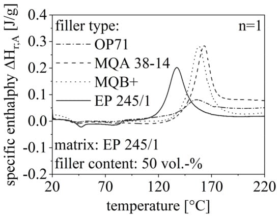
Figure 7.
Route of DSC measurement in the first heating cycle relative to the filler type with 50 vol.-% filler content and compared to pure EP.
As the filler itself is not reactive in the curing process, the amount of material that can be involved in this process is reduced with increasing filler amount. Taking this into account, the exothermal heat flow and with that, the specific enthalpy is reduced due to a higher filler content. However, the filler content must reach a certain level of 50 vol.-% to realize continuous pathways through the EP, which reduces the specific enthalpy. Low filler content inhibits the curing process as the filler is more like a disturbance and further heat flow is needed. Generally, the non-reactive filler inhibits the curing process as the process is driven to higher temperature settings. The isotropy of the filler is less important for the route, but the filler type influences the specific enthalpy significantly.
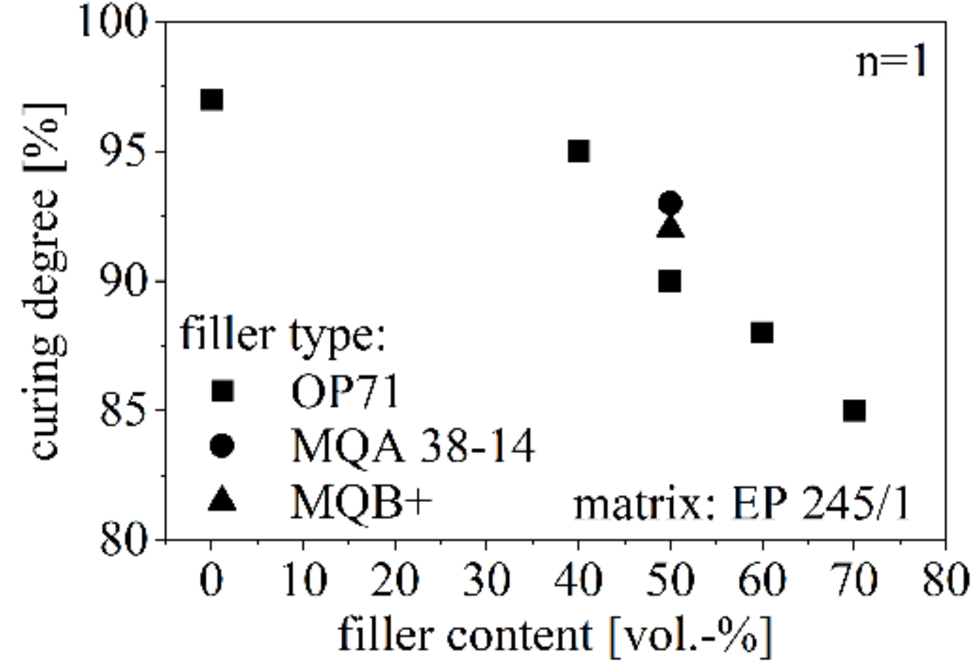
The curing degree Σcuring relative to the filler type and filler content is shown in Figure 8. The curing degree reduces due to increasing filler amount and reaches about 85% for 70 vol.-% of anisotropic SrFeO. The curing degree of NdFeB is slightly higher relative to SrFeO, whereas the isotropy has no influence on the curing degree.
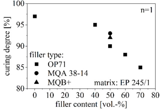
Figure 8.
Curing degree relative to the filler type and amount between 40 and 70 vol.-% with respect to pure EP.
3.3. Flow Behavior of Powdered Compound
The bulk density ρB and the flowability of isotropic NdFeB (MQB+) and anisotropic SrFeO (OP71) are shown in Figure 9 with respect to the filler content. As both parameters act similarly for isotropic and anisotropic NdFeB, the behavior is only depicted for the isotropic type of NdFeB in Figure 9. The bulk density ρB of MQB+ is higher relative to OP71 and increases with the filler amount. The filler content affects ρB of OP71 only slightly and leads to an increase with higher filler amounts. The bulk density ρB of pure EP with the value of 0.65 g/cm3 is slightly lower relative to OP71. The flowability of OP71 is worse relative to MQB+ and significantly influenced by the filler content. There is hardly any influence on the flowability for MQB+. The flowability of pure EP with the value of 254 s was significantly reduced by adding NdFeB.
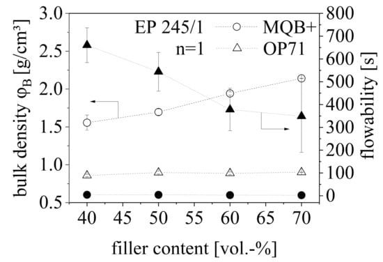
Figure 9.
Bulk density ρB and flowability of a hard magnetic compound with anisotropic (OP71) SrFeO and isotropic NdFeB (MQB+) between 40 and 70 vol.-% filler content.
NdFeB reveals a higher ρB and with that poorer cohesive forces between the particles due to smoother surfaces as it can be seen in Figure 2 relative to SrFeO. Within SrFeO bulk bridges can be broken due to pitching which leads to compression and new orientation of the particles. On the other side, the flowability of SrFeO is lower relative to NdFeB as agglomerates are likely to be built. Especially in the compounding process, this behavior inhibits the process significantly. This effect can be reduced by increasing filler content as the high density of the filler forces the material more to pass the funnel. However, the cohesive forces between the particles as well as the agglomerates lead to values above pure EP whereas the flowability is improved by the larger NdFeB particles with less cohesive forces between the particles.
3.4. Specific Heat Capacity c and Thermal Conductivity λ of Pure Filler Material and Compounds
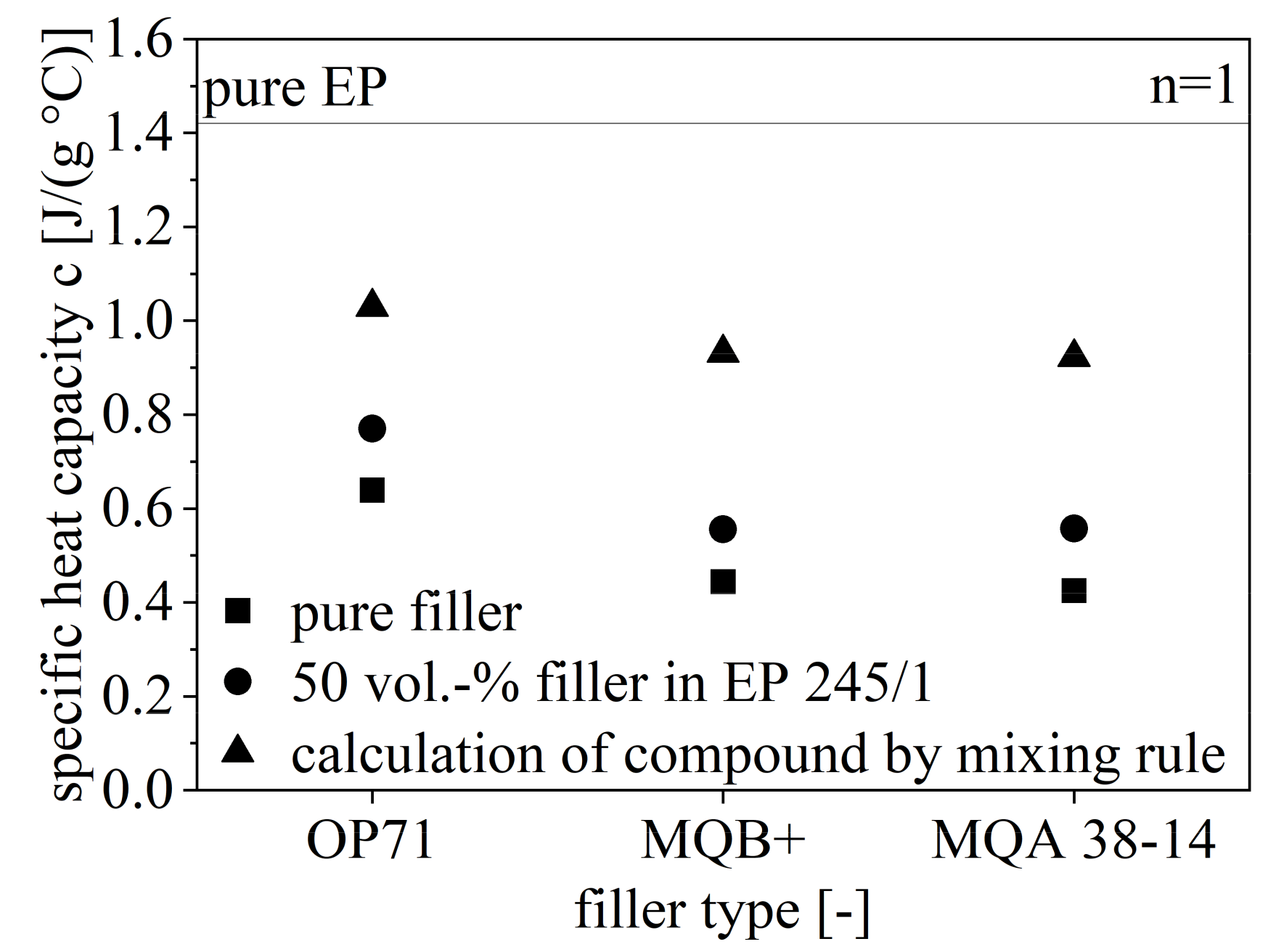
The specific heat capacity c for the pure filler and EP as well as c of the compound with 50 vol.-% filler content is shown in Figure 10. Further, the calculated values for c for the compound with respect to the analyzed values for the pure ingredients are depicted in Figure 10. The specific heat capacity c is reduced from OP71 to MQB+ to MQA 38-14 and reaches about 1/3 greater values for SrFeO with respect to NdFeB. There is no influence of the isotropy on c. Further, the analyzed and calculated values for the compound are different with a similar offset for each filler type. The analyzed value of c for the compound is closer to the pure filler.
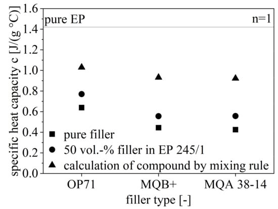
Figure 10.
Specific heat capacity c of the hard magnetic compounds with 50 vol.-% filler content of different fillers relative to pure filler and EP.
With respect to the mixing rule (Equation (3)), the impact of the filler is higher relative to EP as the analyzed values of c are closer to the values of the pure filler. With that, the filler content in the compound does not reveal the behavior regarding c due to higher values.
The extrapolation of the thermal conductivity λ reaches 2.3 W/(mK) for pure SrFeO and 6.1 W/(mK) for pure NdFeB. These parameters do not accord to the values given by the manufacturer specifications (Table 1). However, NdFeB still has a higher thermal conductivity λ with respect to SrFeO.
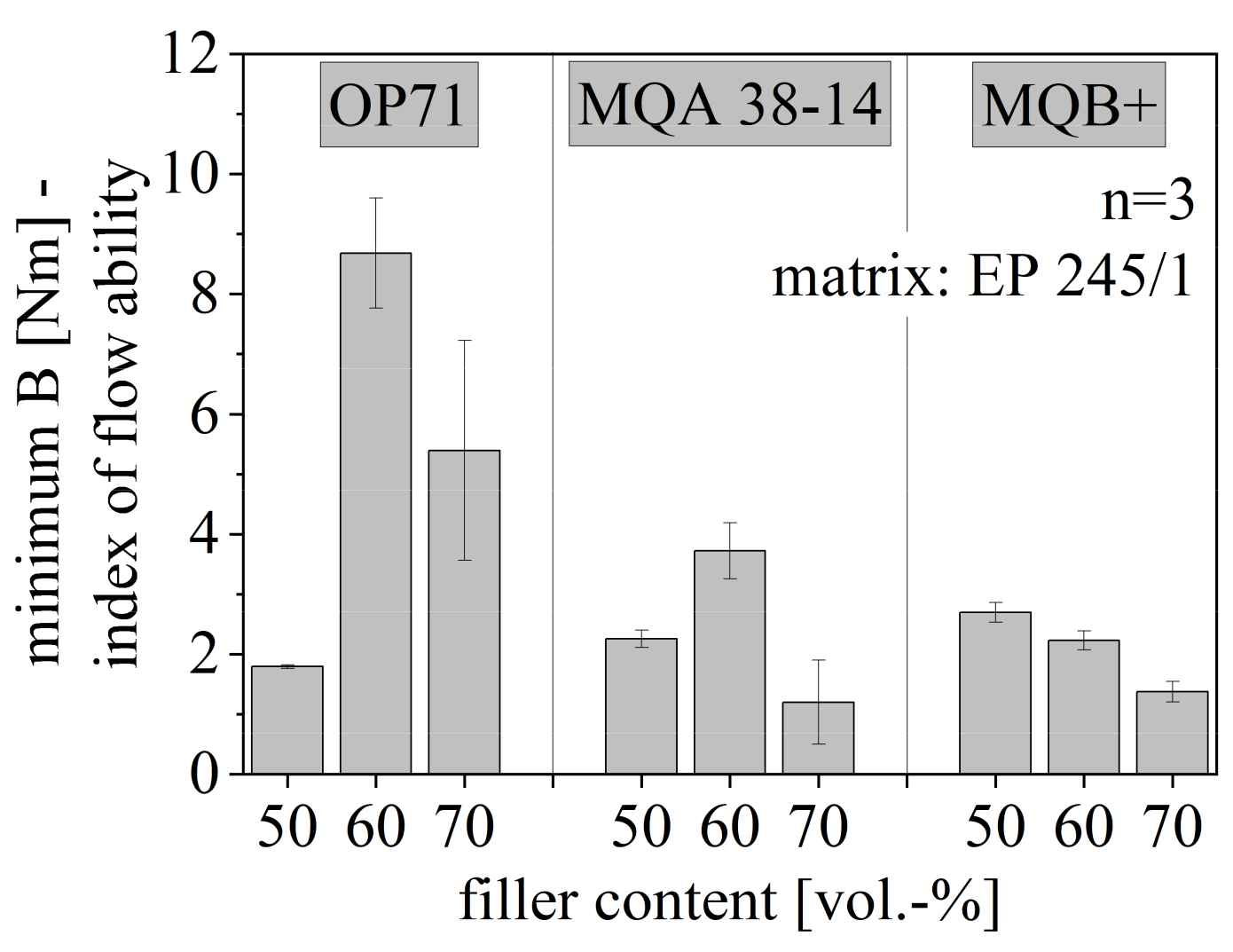
3.5. Flow Behavior
The minimum B and with that, the index of the flowability is depicted in Figure 11 for anisotropic SrFeO (OP71) and both isotropy types of NdFeB (MQA 38-14 and MQB+) relative to the filler content between 50 and 70 vol.-%. For both anisotropic fillers, the flowability decreases with increasing filler content and increases again after reaching more than 60 vol.-% filler content. The route of B decreases continuously for isotropic NdFeB with increasing filler content.
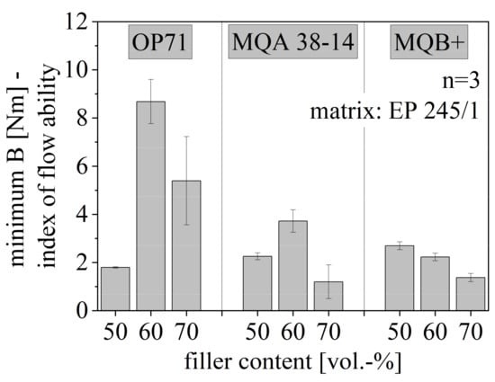
Figure 11.
Flowability of hard magnetic compound with filler content between 50 and 70 vol.-% for different filler types.
It is assumed that the tendency of small particles to build agglomerates enables the improvement of the flow behavior for SrFeO and filler content above 60 vol.-% as not only the particle itself but also the amount of the particles increase the possibility of agglomeration. This was also depicted in the flow behavior of the pure compound in Figure 9. Due to large agglomerates, the flow behavior of the filler approaches the behavior of the matrix in terms of the particle size so that the filler is less of an interfering particle. Therefore, particles that have the tendency of agglomeration increase the flowability after reaching a certain amount of fillers. In terms of the anisotropic NdFeB, it is not likely that agglomeration takes place. The low value of B for high filler amounts of anisotropic NdFeB is reached through improved thermal conditions. NdFeB reveals a higher thermal conductivity λ relative to SrFeO, but a lower specific heat capacity c. Improved thermal conditions and increased flowability can only be reached by higher filler contents due to λ. For anisotropic NdFeB, this benefit is inhibited by interference between the particles due to a preferred direction of the magnetic dipoles.
The flowability of NdFeB is higher relative to SrFeO. As demonstrated in Figure 5 both fillers have a similar particle size numerical speaking, but NdFeB has a few and larger particles. Therefore, it is assumed that the particle size with respect to the particle size distribution is not the reason for the difference in the flowability between the two fillers. The difference in flowability is expected to be due to the different shapes of the particles, which support the flow behavior in terms of plate-like particles. Further, pictures taken in the scanning electron microscope illustrate a difference in the linkage between SrFeO and NdFeB to the matrix material as shown representative for the anisotropic SrFeO type (OP71) and NdFeB type (MQA 38-14) discussed in more detail in chapter 3.7. As NdFeB has hardly any linkage, the particles can be easily picked up and transported by the matrix without interfering with the matrix behavior. This means that even without adhesive forces between the resin and the filler, the form of the particles permits the matrix material to build the network around the filler without being disturbed by the particle. The particle is encapsulated by the resin without linkage to its surface. Therefore, the particle form and adherence behavior of the filler influences the flowability, whereby NdFeB enables a better flow behavior relative to SrFeO.
The flowability is mainly influenced due to the tendency of filler material to build agglomerates, their crystal structure and isotropy and their particle size distribution. Further, the linkage to the matrix is important as this determines the building of holes due to the filler, which acts like a foreign particle, or the encapsulation of the filler by the matrix leading to good transportation, as well as the thermal conditions of the filler. To improve the flowability mainly the material behavior of the filler has to be considered to reach the optimum in the flow behavior.
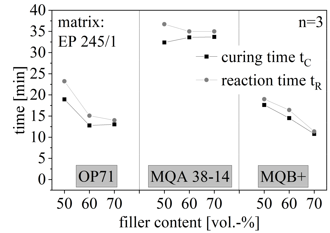
3.6. Curing Behavior and Process Stability
The curing time tC and the reaction time tR and with that the process stability is shown in Figure 12 again for the filler amount between 50 and 70 vol.-% for the anisotropic SrFeO (OP71) and both isotropy types of NdFeB (MQA 38-14 and MQB+). The route of tC and tR are similar for each compound. Both times are reduced with increasing filler content but stagnate at high filler amounts for anisotropic fillers. The isotropic type of NdFeB continuously decreases with rising filler content. The value of the times is the highest for anisotropic NdFeB and the lowest for isotropic NdFeB.
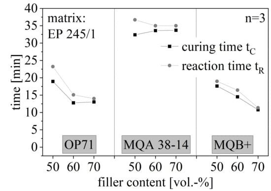
Figure 12.
Curing and reaction time of hard magnetic compound with filler content between 50 and 70 vol.-% for different filler types.
The reduction of tC by an increasing filler amount results in fast curing velocity for high filler contents. Further, the stability decreases with increasing filler content, which results in a small process window and short cycle time. With that, a high amount of particles increases the thermal input, which fastens the cross-linking process. However, NdFeB has a lower linkage to the matrix relative to the SrFeO as shown in Figure 13 in caption 3.7. It can be assumed that the preferred orientation in the anisotropic particles reduces the effect of fast cross-linking processes further due to the crystal structure. Summarizing the thermal conductivity and the heat capacity of the hard magnetic filler fastens the cross-linking process because of the increase in the energy input. This effect is reduced through anisotropic fillers and their preferred orientation, as well as through NdFeB and its poor linkage to the matrix. It is increased by an increasing amount of fillers due to better pathways throughout the resin.
The main influencing factors on the curing and reaction time are the thermal conductivity and the heat capacity of the particles. These two factors define the available energy needed for the chemical process and the energy input in the compound. Factors that reduce this improved thermal input can be the linkage between the filler and the matrix, the crystal structure of the particles and the number of particles. Therefore, again the behavior of the filler has to be taken into account to improve the curing and reaction time of the compound.
This matches well with the DSC measurements shown in Figure 7 as the peak temperature is reached at lower values for isotropic NdFeB relative to anisotropic ones. Further, OP71 and MQB+ reach similar values as the isotropic NdFeB inhibit the curing only due to the low linkage and anisotropic SrFeB due to the crystal structure whereas anisotropic NdFeB due to both–low linkage and crystal structure.
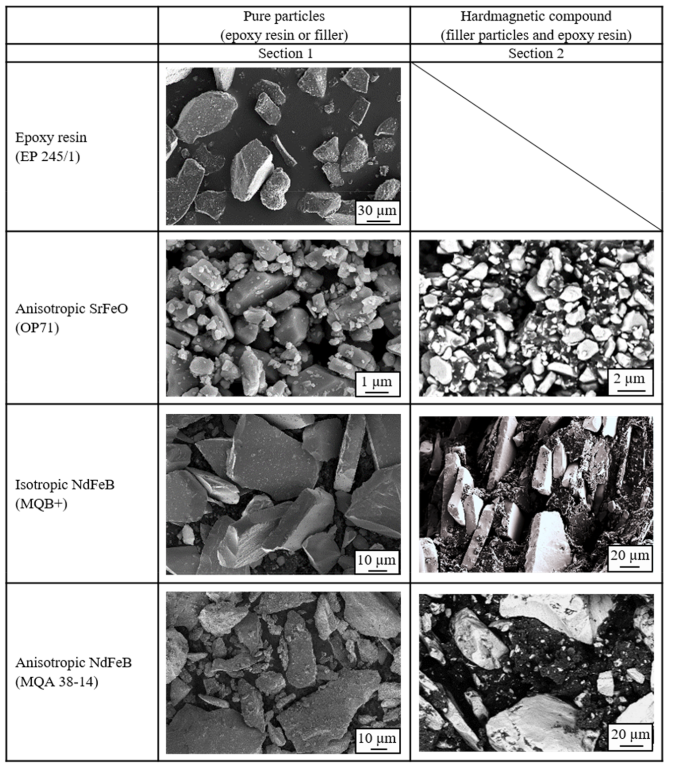
3.7. Particle Surface and Distribution in the Compound
To understand the behavior of the hard magnetic compounds in more detail, the pure materials and the hard magnetic compounds were analyzed in detail using a scanning electron microscope. The filler surface and the position as well as the filler form of the hard magnetic particles are shown in Section 1 of Figure 13 is exemplary for a filler content of 50 vol.-%. The pure epoxy resin reveals single particles with very small fractures on the surface. The particle size of the epoxy resin is significantly reduced in the curing process. The pure anisotropic SrFeO (OP71) exhibits single particles with many smaller ones on the surface. The pure isotropic NdFeB (MQB+) reveals smooth surfaces and plate-like particles without agglomerates or smaller particles on the surface. They are similar to a slate. The pure anisotropic NdFeB (MQA 38-14) has fewer single plates as the isotropic type and more fractures. These fractures stick to the plates to some extent.
The compound with anisotropic SrFeO (OP71) presents partly with attachments of the epoxy resin on the surface of the filler, as shown in Section 2 in Figure 13. The agglomerates are not fully broken probably due to the preferred orientation direction in this type. With that, the smaller particles on the surface, which were already present on the pure filler, remain mainly at their position. Due to the missing ability of the epoxy resin to adhere to the filler surface with respect to the magnetic force of the agglomerates, the holes between the anisotropic fillers are filled with the matrix material without actual attachments. With that, the anisotropic SrFeO are able to generate a homogenous meshwork between the filler and the matrix material without interfacial debonding and exposing holes in the matrix. It can be assumed that the filler has functional groups which are capable of reacting with the resin in that way that strong adherence between filler and resin is missing, but the filler is well integrated with the matrix. This can be related to the network structure (b) in Figure 1 where pathways of the network structure are not interrupted. This leads to better integration of the filler into the resin and further a continuous pathway in terms of thermal conductivity.
The compound with isotropic NdFeB (MQB+) depicts single plates with only small adherence, as shown in Section 2 in Figure 13. It seems like the fillers are almost foreign objects with no integration into the epoxy resin. The behavior of the isotropic NdFeB (MQB+) is very similar to the network structure portrayed in a) in Figure 1. The pathway in the network structure is interrupted due to the filler, forcing the structure to be built around the particle without integration of it. The compound with anisotropic NdFeB (MQA 38-14) shows more attachments of the epoxy resin on the filler plates due to the less smooth surface of the fillers, as depicted in Section 2 in Figure 13. The integration of the filler in the matrix is better compared to the isotropic type of NdFeB but worse compared to SrFeO. The functional groups of NdFeB do not have the ability to react with the filler in order to integrate itself into the matrix. Only the surface roughness of anisotropic NdFeB allows some attachments to the resin. It can be assumed that surface treatments of the filler in the case of NdFeB might improve the reaction capability of filler and resin, leading to better integration of the filler. This can further reduce the viscosity of the compound with respect to the filler being less of a foreign object. With that, the better orientation of the fillers can be reached as well as reduced voids and holes [40]. The cohesive forces built with respect to the bulk density ρB further proves the network structure relative to the filler type. Moreover, the low importance of the isotropy on the route of DSC measurements is demonstrated with respect to the network theory for each filler type.
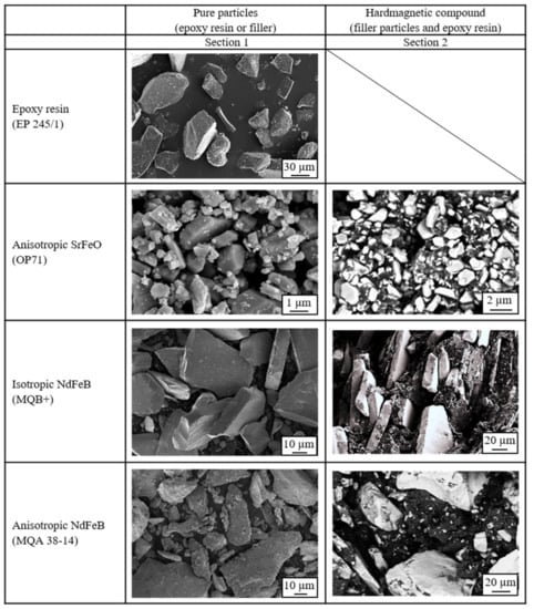
Figure 13.
Overview of the pure filler and epoxy resin surface as well as the position and distribution of the fillers in the hard magnetic compound with 50 vol.-% filler content.
Figure 13.
Overview of the pure filler and epoxy resin surface as well as the position and distribution of the fillers in the hard magnetic compound with 50 vol.-% filler content.
3.8. Magnetic Properties
The magnetic properties can be characterized by three typical parameters-the remanence BR, the coercivity HcB and the maximal energy product (BH)max–measured within the hysteresis loop using a permagraph. As those three parameters reveal similar behavior within this paper, only the remanence BR will be discussed with respect to the evaluation of the magnetic properties. BR increases with further filler content in almost linear correlation despite the standard deviation of the compound with 50 vol.-% SrFeO (OP71). The standard deviation of the isotropic NdFeB (MQB+) compound is lower relative to anisotropic NdFeB compounds probably due to the missing preferred direction in terms of the isotropic compound. With that, the orientation of the fillers has no impact on the magnetic properties. However, the standard deviation of both NdFeB compounds is significantly higher relative to the SrFeO compound as SrFeO is more integrated into the network as shown in chapter 3.7. The impact of the less integration of the filler is reduced in terms of the isotropic NdFeB. The magnetic properties of the anisotropic SrFeO compound are lower relative to the ones of the NdFeB compound. As the fillers are not orientated in the cavity, the BR of isotropic and anisotropic NdFeB compounds are similar. The magnetic properties in terms of BR are portrayed in Figure 14 with respect to the anisotropic SrFeO and the isotropic as well as the anisotropic NdFeB compound with filler content between 40 and 70 vol.-%.
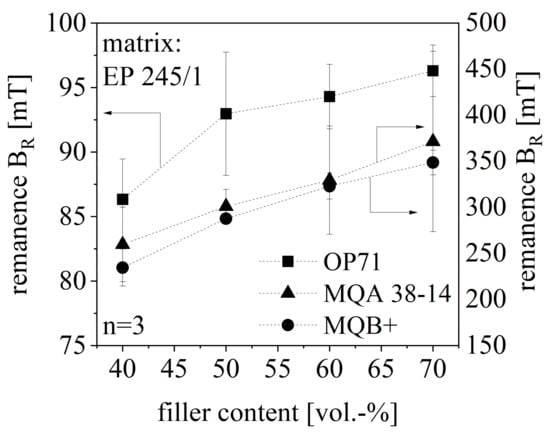
Figure 14.
Remanence BR of hard magnetic compound with filler content between 40 and 70 vol.-% for different filler types.
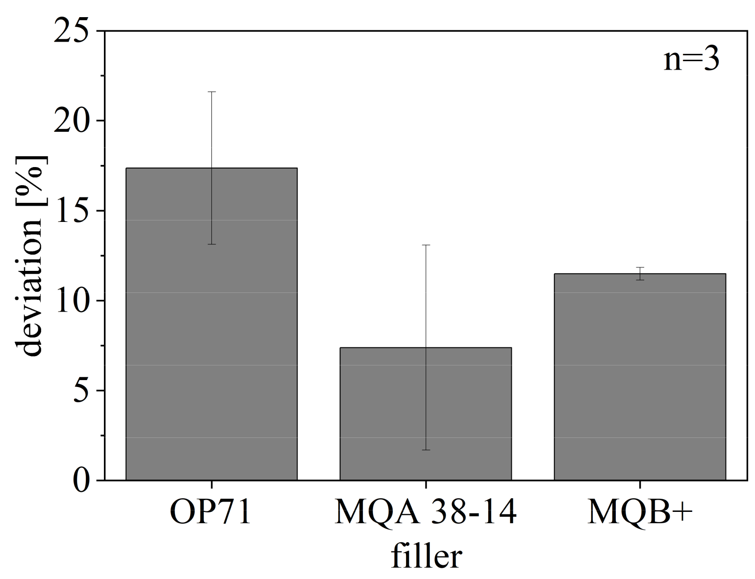
The deviation of BR of the compounds relative to the ideal properties with respect to the pure fillers is shown in Figure 15. The ideal BR of the fillers relative to [22] is reduced through the filler content by 50% in terms of a filler amount of 50 vol-.% and again in terms of the isotropic fillers by 50% due to non-usage of the potential of the material or in terms of the anisotropic fillers by 50% due to the missing orientation. The deviation reaches up to 20% in terms of the SrFeO compound, as the smaller particles are less orientated only in terms of the shearing and with respect to the higher integration within the network. The deviation of NdFeB is lower relative to SrFeO but reaches only a small standard deviation in terms of isotropic NdFeB. The anisotropic NdFeB reveals a high standard deviation due to the impact of the missing orientation and the less integration in the network.
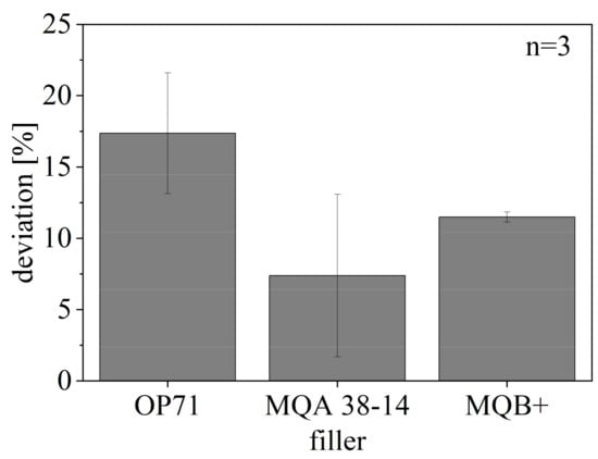
Figure 15.
Deviation of remanence BR of hard magnetic compound with filler content of 50 vol.-% for different filler types compared to ideal remanence BR of compound relative to [22].
3.9. Correlation between the Influencing Factors of the Flow and Curing Behavior
The paper depicts that several factors influence the flow and curing behavior of highly filled thermoset compounds based on epoxy resin. These influencing factors can be applied to any filler system as they are based on the material behavior of particles. It was shown that not only the mean particle size but moreover the numerical distribution of the filler size is important to know in order to define the filler tendency of building agglomerates or of filling small gaps between particles. A high amount of small particles increases the probability of agglomeration, but only anisotropic particles further build agglomerates due to their preferred orientation. As the hard magnetic filler itself is not reactive in the curing process an increasing amount of filler reduces the material involved in the curing process. However, the thermal conductivity and the heat capacity as well as the linkage of filler and matrix or the agglomeration building of the fillers influence the curing process. With that, the filler might not have a direct influence on the curing process but affects this reaction indirectly.
Influencing factors on the flowability are the crystal structure and isotropy of fillers as they define the tendency of building agglomerates. Due to large agglomerates, the flow behavior of the filler approaches the behavior of the matrix in terms of the particle size so that the filler is less of an interfering particle. Therefore, particles that have the tendency of agglomeration increase the flowability after reaching a certain amount of fillers. Further, their particle size distribution, the particle shape, the linkage to the matrix, the adherence behavior of the filler and matching of the filler size compositions is important. The flow behavior is supported in terms of plate-like particles. Fillers with a poor linkage to the matrix can easily be picked up and transported by the matrix without interfering with the matrix behavior. With that particles like NdFeB enhances the flow behavior due to the particle form and the adherence behavior.
The thermal conductivity and the heat capacity of the particles are the main factors for the curing behavior. These two factors define the available energy needed for the chemical process and the energy input in the compound. With that, the curing time tC and the stability decrease with increasing filler content. Further, the linkage between the filler and the matrix, the crystal structure of the particles, and the amount of particles has to be considered. As NdFeB reveals hardly any linkage to the matrix the curing and reaction time behavior of NdFeB is poorer relative to SrFeO. Further, the curing and reaction time behavior is poorer for anisotropic fillers as the preferred orientation reduces the effect of fast cross-linking processes due to the crystal structure. Additionally, the filler distribution in the matrix is less homogeneous.
The thermal conductivity of the filler and its impact on the reaction is mainly influenced by the network structure and the pathways. NdFeB portrays less adhesion to the resin with respect to its functional groups whereas SrFeO has such functional groups, which are capable to react with the resin and integrate the filler. With that, the pathways of the network structure and the thermal conductivity are defined which are further influenced by the linkage between matrix and filler. This linkage to the matrix is important as this defines whether holes are built and filler act like a foreign particle or the matrix encapsulate the filler leading to good transportation. With respect to [40], the increased thermal conductivity of NdFeB becomes negligible in terms of a high filler amount of SrFeO due to a compensation of the reduced thermal conductivity by good pathways along with the fillers and a good adherence between matrix and filler. In the case of SrFeO, the high filler amount improves the building of pathways.
Summarizing NdFeB reveals less adhesion to the resin with respect to its functional groups whereas SrFeO has such functional groups, which are capable to react with the resin and integrate the filler. Further isotropic NdFeB (MQB+) and SrFeO mark the boundary in the network structure with anisotropic NdFeB (MQA 38-14) being the intermediate case. With that, the pathways of the network structure and the thermal conductivity are defined which are further influenced by the linkage between matrix and filler.
4. Conclusions
It was shown in detail that the filler content, filler size distribution, crystal structure and isotropy as well as the filler size compositions, the linkage to the matrix, the thermal conductivity, and the heat capacity are the main factors that have to be considered while selecting the filler material. The influencing factors on the flowability and the curing behavior with respect to the relationship between the factors are shown in Figure 16 to provide a good overview. Further recommendations regarding the setting parameters are given in order to improve the flowability or the curing behavior separately. Note that the direction of the arrow indicates which parameters have an impact and which one is influenced by another. It is important that the characterization of the flow and curing behavior in the measuring mixing is assumed to be a decent approximation of the injection molding process. However, especially the shear rate is much higher in the injection molding process. Therefore, the material behavior has to be further evaluated in the injection molding process with respect to the general behavior investigated in this paper.
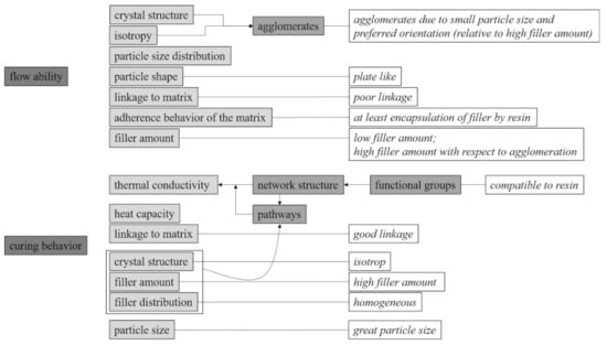
Figure 16.
Overview of the influencing factors of flowability and curing behavior and the relationship between these factors as well as setting parameters to improve flowability and curing behavior with respect to hard magnetic compounds.
Investigations in the magnetic properties and the influence of the flow and curing behavior, especially in terms of the network theory are proved.
Further research will be done on the filler form to find a general rule for their influence on the flow and curing behavior. In addition, the matrix material shall be varied to evaluate the transferability of the influencing factors for epoxy resin on different matrix materials. This would allow a general declaration of influencing factors on the flow and curing behavior independent of the matrix and filler material.
Author Contributions
U.R.: Conceptualization, Methodology, Validation, Investigation, Writing–Original Draft, Visualization; D.D.: Writing–Review & Editing, Supervision, Project. All authors have read and agreed to the published version of the manuscript.
Funding
This research was funded by the German Research Foundation (DFG) within the project DFG DR 412/36-1 “Duroplastgebundene spritzgegossene Dauermagneten mit definierter Magnetisierungsstruktur”.
Data Availability Statement
Restrictions apply to the availability of these data. Data was obtained within the project HYDRESS with the funding code DFG DR 412/36-1 and is available with the permission of the author.
Acknowledgments
We want to thank the German Research Foundation (DFG) for funding the project DFG DR 412/36-1 “Duroplastgebundene spritzgegossene Dauermagneten mit definierter Magnetisierungsstruktur”.
Conflicts of Interest
The authors declare no conflict of interest. The funders had no role in the design of the study; in the collection, analyses, or interpretation of data; in the writing of the manuscript, or in the decision to publish the results.
References
- Drummer, D. Prozessführung beim Spritzgießen kunststoffgebundener Dauermagnete. In Kunststoffgebundene Dauermagnete; Springer: Düsseldorf, Germany, 2004. [Google Scholar]
- Hagemann, B. Kunststoffgebundene Magnete in der Antriebstechnik—Möglichkeiten und Grenzen. In Kunststoffgebundene Dauermagnete; Springer: Düsseldorf, Germany, 2004. [Google Scholar]
- Sadovnikov, A.V.; Odintsov, S.A.; Beginin, E.N.; Grachev, A.A.; Gubanov, V.A.; Sheshukova, S.E.; Sharaevskii, Y.P.; Nikitov, S.A. Nonlinear Spin Wave Effects in the System of Lateral Magnonic Structures. JETP Lett. 2018, 107. [Google Scholar] [CrossRef]
- Schliesch, T. Sensormagnete: Vielfältig gestaltbare Spritzgussteile: Magnete mit virtuoser Polverteilung. Industrieanzeiger, 7 June 2010; p. 20. [Google Scholar]
- Johannaber, F.; Michaeli, W. Handbuch Spritzgießen, 2nd ed.; Carl Hanser Verlag: München, Germany, 2004. [Google Scholar]
- Ormerod, J.; Constantinides, S. Bonded permanent magnets: Current status and future opportunities (invited). J. Appl. Phys. 1997, 81, 4816–4820. [Google Scholar] [CrossRef] [Green Version]
- Inaguma, T.; Sakamoto, H.; Mukai, T. Magnetic properties of resin-bonded magnets of anisotropic Nd-Fe-B-Cu powder. IEEE Transl. J. Magn. Jpn. 1993, 8, 27–32. [Google Scholar] [CrossRef]
- Reppel, G.W. Duroplastgepresste Magnete—Werkstoffe, Verfahren und Eigenschaften. In Kunststoffgebundene Dauermagnete; Springer: Düsseldorf, Germany, 2004; pp. 14–36. [Google Scholar]
- Lagorce, L.; Allen, M. Magnetic and mechanical properties of micromachined strontium ferrite/polyimide composites. J. Microelectromechanical Syst. 1997, 6, 307–312. [Google Scholar] [CrossRef] [Green Version]
- MS Schramberg GmbH & Co. KG. Umfassend; MS Schramberg GmbH & Co.: Schramberg, Germany, 2010. [Google Scholar]
- Kurth, K.H.; Drummer, D. Influences of the Magnetic Properties of Injection Molded Multipolar Rings. Int. Polym. Process. 2016, 31, 356–363. [Google Scholar] [CrossRef]
- Baur, E.; Brinkmann, S.; Osswald, T.; Rudoplh, N.; Schmachtenberg, E. Saechtling Kunststoff Taschenbuch, 31st ed.; Carl Hanser Verlag: München, Germany, 2013. [Google Scholar]
- Glöser-Chahoud, S.; Kühn, A.; Espinoza, L.A.T. Flobale Verwendungsstrukturen der Magnetwerkstoffe Neodym und Dysprosium: Eine szenariobasierte Analyse der Auswirkung der Diffusion der Elektromobilität auf den Bedarf an Seltenen Erden; Working Paper Sustainability and Innovation; Fraunhofer ISI: Karlsruhe, Germany, 2016. [Google Scholar]
- Rösel, U.; Drummer, D. Injection Moulding of Multipolar Polymer-Bonded Magnets into Soft Magnetic Inserts for Rotors in Reluctance Motors. Magnetism 2021, 1, 2. [Google Scholar] [CrossRef]
- Baran, W. Magnetische Werkstoffe für Energiewandler und Statistische Systeme. In Magnetische Werkstoffe; Verlag TÜV: Rheinland, Germany, 1990. [Google Scholar]
- Michalowsky, L. Magnettechnik: Grundlagen, Werkstoffe, Anwendungen, 3rd ed.; Vulkan-Verl.: Essen, Germany, 2006. [Google Scholar]
- Wellmann, P. Materialien der Elektronik und Energietechnik: Halbleiter, Graphen, Funktionale Materialien; Springer Fachmedien Wiesbaden: Wiesbaden, Germany, 2017. [Google Scholar]
- Cassing, W.; Seitz, D. Dauermagnete: Mess und Magnetisierungstechnik, 2nd ed.; Expert-Verl.: Renningen, Germany, 2015. [Google Scholar]
- Hering, E.; Martin, R.; Stohrer, M. Physik für Ingenieure, 12th ed.; Springer Vieweg: Berlin/Heidelberg, Germany, 2016. [Google Scholar]
- Koch, J. Dauermagentische Werkstoffe und ihre Anwendungen. Phys. Blätter 1975, 31, 439–455. [Google Scholar] [CrossRef]
- Ma, B.; Sun, A.; Gao, X.; Bao, X.; Li, J.; Lang, H. Preparation of anisotropic bonded NdFeB/SmFeN hybrid magnets by mixing two powders. J. Magn. Magn. Mater. 2018, 457, 70–74. [Google Scholar] [CrossRef]
- Drummer, D. Verarbeitung und Eigenschaften Kunststoffgebundener. Dauermagnete. Dissertation, University of Erlangen-Nuremberg, Erlangen, Germany, 2004. [Google Scholar]
- Stitz, S. Spritzgießtechnik: Verarbeitung, Maschine, Peripherie, 2nd ed.; Hanser: München, Germany, 2004. [Google Scholar]
- Kurth, K.; Drummer, D. Variation of the Pole Length in Pole-Oriented Bonded Rings due to the Location and Number of Injection Points. J. Polym. 2017, 2017, 1–11. [Google Scholar] [CrossRef] [Green Version]
- Hoven-Nievelstein, W. Wir bewegen uns in Richtung Spezialitäten. Kunststoffe—Werkstoffe Verarbeitung Anwendung 2008, 6, 24–29. [Google Scholar]
- Altmann, N.; Halley, P.J.; Cooper-White, J.; Lange, J. The Effects of Slica Fillers on the Gelation and Viltrification of Highly Filled Epoxy-Amine Thermosets. In Macromolecular Symposia; WILEY-VCH Verlag GmbH: Weinheim, Germany, 2001; Volume 169, pp. 171–177. [Google Scholar]
- Bae, J.; Jang, J.; Yoon, S.-H. Cure Behavior of the Liquid-crystalline Epoxy/Carbon Nanotube System and the Effect of surface treatment of carbon fillers on cure reaction. Macromol. Chem. Phys. 2002, 203, 2196. [Google Scholar] [CrossRef]
- Dutta, A.; Ryan, M. Effect of fillers on kinetics of epoxy cure. J. Appl. Polym. Sci. 1979, 24, 635–649. [Google Scholar] [CrossRef]
- Wang, X.; Jin, J.; Song, M.; Lin, Y. Effect of graphene oxide sheet size on the curing kinetics and thermal stability of epoxy resins. Mater. Res. Express 2016, 3, 105303. [Google Scholar] [CrossRef] [Green Version]
- Halley, P.J. A new chemorheological analysis of highly filled thermosets used in integrated circuit packaging. J. Appl. Polym. Sci. 1997, 64, 95–106. [Google Scholar] [CrossRef]
- Altmann, N.; Halley, P.J. The effect of follers on the chemorheology of highly filled eopxy resin: I. Effects on cure transitions and kinetics. Polym. Int. 2003, 52, 113–119. [Google Scholar] [CrossRef]
- Zhao, Z.; Zhanyu, Z.; Drummer, D. Thermal conductivity of alumininosilicate and aluminium oxide filled thermosets for injection molding. Polymers 2018, 10, 457. [Google Scholar] [CrossRef] [Green Version]
- Zhao, Y.; Drummer, D. Influence of filler content and filler size on the curing kinetics of an epoxy resin. Polymers 2019, 11, 1797. [Google Scholar] [CrossRef] [PubMed] [Green Version]
- Yushanov, S.P.; Isayev, A.I.; Levin, V.Y. Perolation simulation of the network degradation during ultrasonic devulcanization. J. Polym. Sci. Part B Polym. Phys. 1996, 34, 2409–2418. [Google Scholar] [CrossRef]
- Maenz, T.; Hülder, G.; Gehde, M. Influence of flow behavor of different matrix materials on the orientation of anisotropic magnetic particles during injection molding. AIP Conf. Proc. 2016, 1779, 20011. [Google Scholar]
- Ehrenstein, G.W.; Riedel, G.; Trawiel, P. Praxis der Thermischen Analyse von Kunststoffen, 2nd ed.; Carl Hanser Verlag: München, Germany, 2003. [Google Scholar]
- Kummer Semicondutor Technology. Aushärtung von Epoxidharzen und Glasübergangstemperatur (Tg). 2020. Available online: https://www.jpkummer.com/sites/default/files/Aushärtung%20von%20Epoxidharzen%20und%20Glasübergangstemperatur%20%28Tg%29.pdf#:~:text=Hier%20ist%20ein%20DSC%20H%C3%A4rtungsprofil%20eines%20typischen%20Epoxidsystems,schnellste%20H%C3%A4rtung%20dieses%20Produktes%20bei%20dieser%20Temperatur%20erfolgt (accessed on 26 November 2021).
- Schmid, M. Selektives Lasersintern (SLS) mit Kunststoffen: Technologie, Prozesse und Werkstoffe; Hanser: München, Germany, 2015. [Google Scholar]
- Brabender, Brabender Messkneter: Für Materialentwicklung und Qualitätskontrolle; Brabender® GmbH & Co: Duisburg, Germany, 2017.
- Huang, X.; Iizuka, T.; Jiang, P.; Ohki, Y.; Tanaka, T. Role of Interface on the Thermal Conductivitiy of Highly Filled Dielectric Epoxy/AlN Composites. J. Phys. Chem. C 2012, 116, 13629–13639. [Google Scholar] [CrossRef]


Publisher’s Note: MDPI stays neutral with regard to jurisdictional claims in published maps and institutional affiliations. |
© 2021 by the authors. Licensee MDPI, Basel, Switzerland. This article is an open access article distributed under the terms and conditions of the Creative Commons Attribution (CC BY) license (https://creativecommons.org/licenses/by/4.0/).