A Novel Analytical Formulation of the Magnetic Field Generated by Halbach Permanent Magnet Arrays
Abstract
:1. Introduction
2. Halbach PM Disposition and Properties
- -
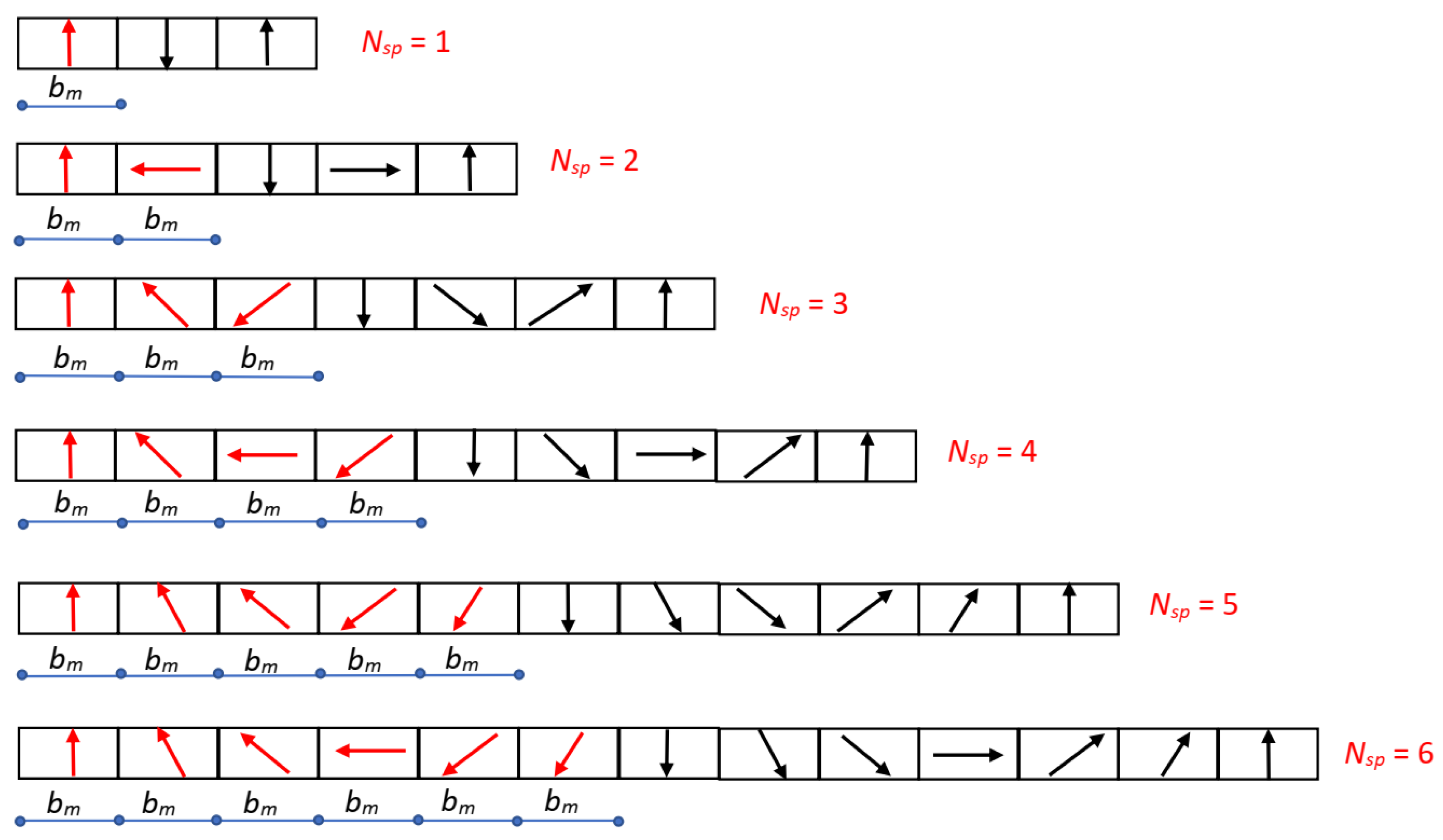
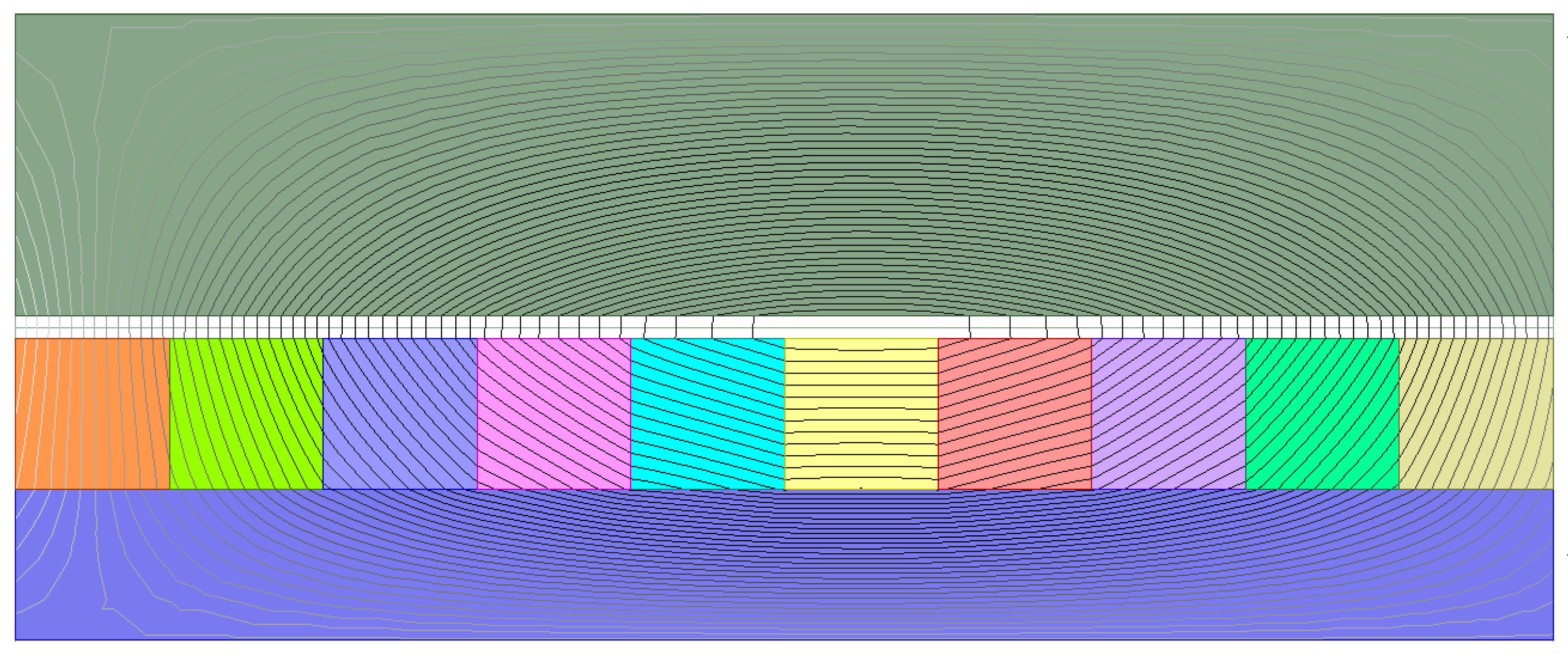
- the flux density distribution amplitude is reinforced in the upper surface of the array, in the air gap, while it is weakened in the lower surface;
- -
- this different distribution leads to the strengthening of the magnetic field where the tangential force is produced, while it reduces the need for a thick yoke width, lightening the mass and the inertia of the moving part;
- -
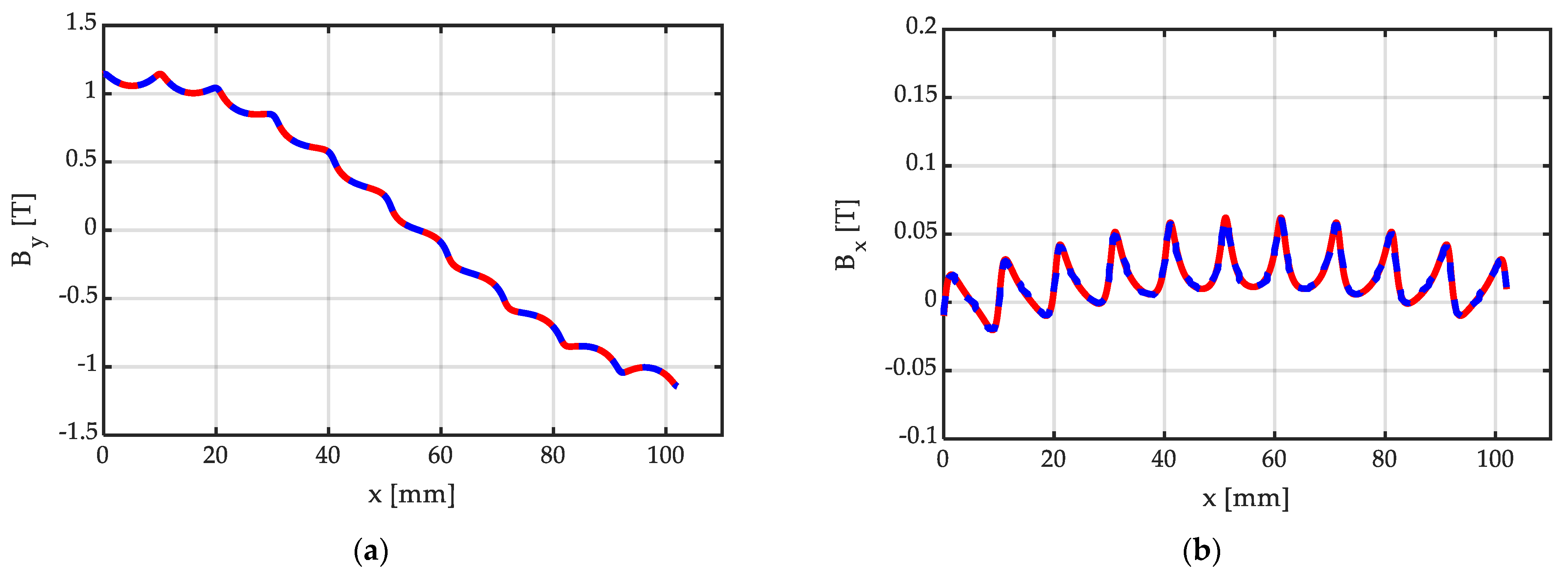
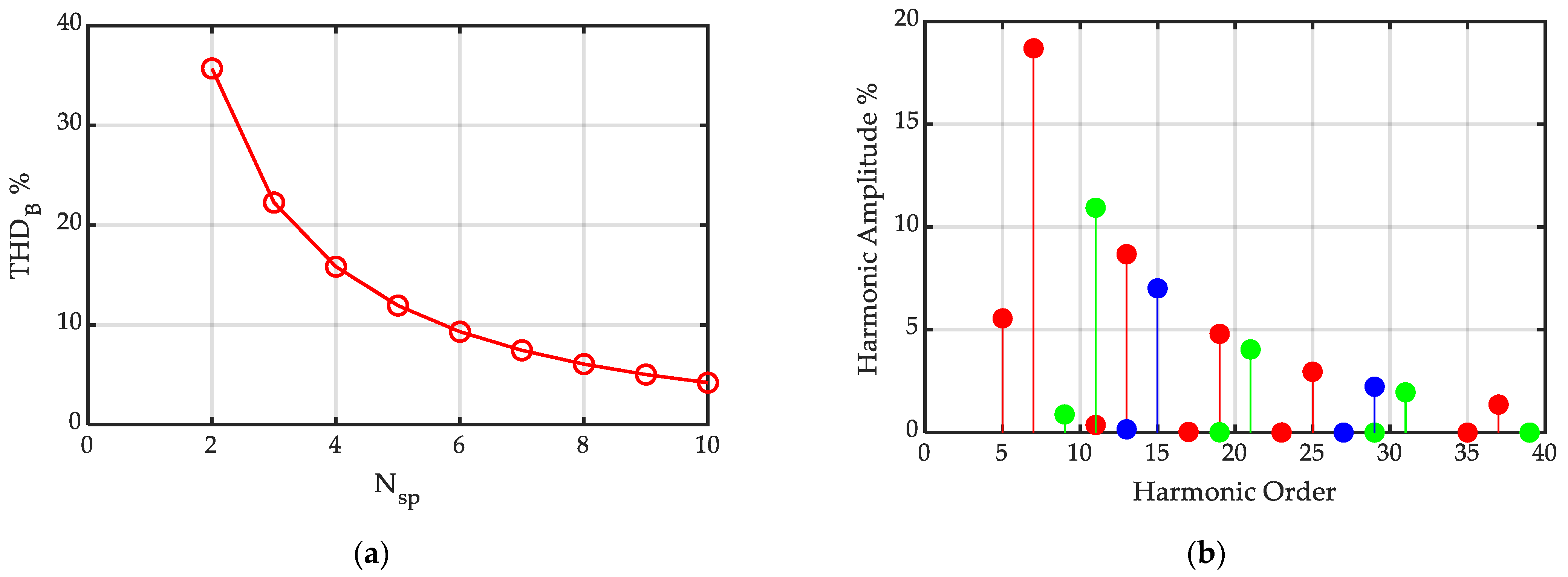
- through the increase in the number of segments per pole, the shape of the normal flux density distribution in the air gap becomes almost sinusoidal, which leads to the obtention of more sinusoidal EMF waveforms in the windings, and a smoother force with reduced ripple;
- -
- of course, the increase in the number of segments per pole implies increasing tolerance issues in the Halbach array assembly, and higher costs for the device: this requires to find a trade-off between the performance quality and system complexity.
3. Magnetic Field between Smooth Ferromagnetic Surfaces
3.1. Introduction to the Model and Elementary Blocks
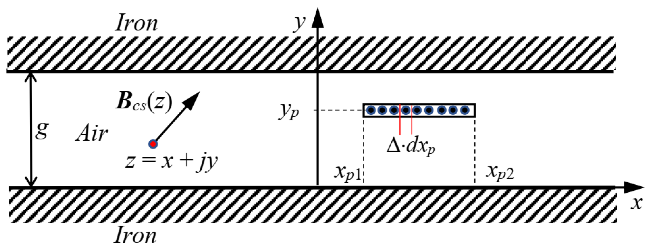
- The stator and moving surfaces are supposed to be smooth, and separated by an air gap of uniform width;
- The magnetic field is solved in 2D, lying in the paper plane, and assumed invariant in the direction perpendicular to the paper plane;
- The machine is supposed to extend indefinitely in the direction perpendicular to the paper plane, so that the end effects are negligible;
- The relative recoil permeability (typically in the range 1.05–1.10 for rare earth PM materials) is assumed to be equal to the vacuum permeability (µr = 1); thus, at each point inside the air-gap width, it is assumed that B(z) = μo∙H(z) occurs, both in air and in the PMs;
- The iron permeability is assumed to be infinite, so the method of superimposition can be used;
- The iron parts are perfectly laminated; thus, no eddy current can be induced in the iron by the varying magnetic field;
- The conductors placed inside the air gap extend indefinitely perpendicular to the paper plane;
- The skin effect due to alternating currents flowing in the conductors is neglected.
3.2. Air-Gap Magnetization Due to a Current Sheet Disposed Normally to the Iron Surfaces
3.3. Air-Gap Magnetization Due to a Current Sheet Disposed Tangentially to the Iron Surfaces
3.4. PM Magnetized along an Axis Orientated Normally to the Iron Surfaces
3.5. PM Magnetized along an Axis Tangentially Orientated to the Iron Surfaces
3.6. Halbach PM Segment with Magnetization Orientated according to an Angle θpm
4. The Halbach PM Arrays
Halbach Array Using the PM Segment Model
5. Calculation Time Comparison between Analytical and FEM Approaches
- -
- the number of calculated points adopted in the analytical method (500), uniformly distributed within the pole pitch τ, is chosen in a such a way to correctly reproduce the flux density distribution everywhere within τ, for all the considered cases of Table 2;
- -
- the calculation time in the analytical method corresponds to the total time needed to evaluate the x and y flux density components in the chosen number of points;
- -
- the calculation time in the FEM numerical approach corresponds to just the time to solve the field; it does not include the time needed to calculate the x and y flux density components in the chosen number of points.
- -
- the accuracy of FEM analysis depends on the mesh refinement level, while the analytical field calculation in each point is direct, without any discretization refinement;
- -
- the calculation times of the cases 1, 2, and 3 are low (of the order of 0.1 s), while the calculation times of the cases 4 and 5 are higher (of the order of 0.2–0.3 s): in fact, the cases 1 and 2 include 2 current sheets, the case 3 includes 4 current sheets, while the case 4 includes 6 × (1 + 2 × 2) = 30 current sheets; finally, the case 5 includes 10 × (1 + 2 × 2) = 50 current sheets. In fact, generally, the field superposition of an higher number of current sheets requires an higher calculation time.
6. Conclusions
Author Contributions
Funding
Institutional Review Board Statement
Informed Consent Statement
Data Availability Statement
Conflicts of Interest
Nomenclature
| conjugate of the complex quantity A (written in bold) | |
| bm | peripheral width of the PM [m] |
| Bcs | flux density due to a current sheet [T] |
| Bx, By | x, y components of the B vector in the air gap [T] |
| BH | flux density vector of a generic Halbach segment inside an array [T] |
| BH1 | flux density vector of a Halbach segment centred at the origin [T] |
| BH1.pole | flux density due to a group of Nsp PM Halbach segments of one pole [T] |
| BH.multi.pole | flux density due to multiple peripherally adjacent Halbach arrays [T] |
| g | total equivalent air-gap width (g = hm + δ) [m] |
| hcs | linear extension of a current sheet [m] |
| hm | normal height of the PM [m] |
| Hc | magnetic strength due to a current I in a concentrated conductor [A/m] |
| Hc0 | PM recoil line linearly extrapolated coercive force [A/m] |
| HH1 | magnetic strength of a single Halbach array segment [A/m] |
| HH1_Δx | magnetic strength due to a Halbach segment, displaced by Δx [A/m] |
| Hncs | magnetic strength due to a normally orientated current sheet [A/m] |
| Htcs | magnetic strength due to a tangentially orientated current sheet [A/m] |
| HPM.n | magnetic strength due to a centered PM, normally magnetized [A/m] |
| HPM.n_Δx | magnetic strength due to a normally magnetized PM, displaced by Δx [A/m] |
| HPM.t | magnetic strength due to a centered PM, tangentially magnetized [A/m] |
| HPM.t_Δx | magnetic strength due to a tangentially magnetized PM, displaced by Δx [A/m] |
| magnetization vector of a PM [A/m] | |
| Mx, My | x, y components of the M vector of a PM [A/m] |
| Nsp | number of Halbach segments per pole [-] |
| THDB | THD of the flux density distribution due to a Halbach array [%] |
| z = x + jy | complex coordinate of the air-gap point where the field is calculated [m] |
| zp = xp + jyp | complex coordinate of the point p of the current carrying conductor [m] |
| βm | angular displacement between near-segment magnetization vectors [deg] |
| δ | mechanical air gap (distance between iron- and PM-faced surfaces) [m] |
| Δ | linear current density of a current sheet distribution [A/m] |
| μo | vacuum permeability [H/m] |
| μr | PM recoil permeability [pu] |
| θpm | orientation of a PM segment magnetization vector, referred to the x axis [deg] |
| τ | pole pitch, peripheral extension of one pole [m] |
References
- Koo, M.-M.; Choi, J.-Y.; Shin, H.-J.; Kim, J.-M. No-Load Analysis of PMLSM With Halbach Array and PM Overhang Based on Three-Dimensional Analytical Method. IEEE Trans. Appl. Supercond. 2016, 26, 0604905. [Google Scholar] [CrossRef]
- Zhu, Z.Q.; Howe, D. Halbach permanent magnet machines and applications—A review. Proc. Inst. Elect. Eng. Electr. Power Appl. 2001, 148, 299–308. [Google Scholar] [CrossRef]
- Okita, T.; Harada, H. 3-D Analytical Model of Axial-Flux Permanent Magnet Machine with Segmented Multipole-Halbach Array. IEEE Access 2023, 11, 2078–2091. [Google Scholar] [CrossRef]
- Zhao, Y.; Ren, X.; Fan, X.; Li, D.; Qu, R. A High Power Factor Permanent Magnet Vernier Machine with Modular Stator and Yokeless Rotor. IEEE Trans. Ind. Electron. 2023, 70, 7141–7152. [Google Scholar] [CrossRef]
- Pérez, R.; Pelletier, A.; Grenier, J.-M.; Cros, J.; Rancourt, D.; Freer, R. Comparison between Space Mapping and Direct FEA Optimizations for the Design of Halbach Array PM Motor. Energies 2022, 15, 3969. [Google Scholar] [CrossRef]
- Mallek, M.; Tang, Y.; Lee, J.; Wassar, T.; Franchek, M.A.; Pickett, J. An Analytical Subdomain Model of Torque Dense Halbach Array Motors. Energies 2018, 11, 3254. [Google Scholar] [CrossRef]
- Zhang, X.; Zhang, C.; Yu, J.; Du, P.; Li, L. Analytical Model of Magnetic Field of a Permanent Magnet Synchronous Motor with a Trapezoidal Halbach Permanent Magnet Array. IEEE Trans. Magn. 2019, 55, 7. [Google Scholar] [CrossRef]
- Guo, R.; Yu, H.; Xia, T.; Shi, Z.; Zhong, W.; Liu, X. A Simplified Subdomain Analytical Model for the Design and Analysis of a Tubular Linear Permanent Magnet Oscillation Generator. IEEE Access 2018, 6, 42355–42367. [Google Scholar] [CrossRef]
- Song, Z.; Liu, C.; Feng, K.; Zhao, H.; Yu, J. Field Prediction and Validation of a Slotless Segmented-Halbach Permanent Magnet Synchronous Machine for More Electric Aircraft. IEEE Trans. Transp. Electrif. 2020, 6, 1577–1591. [Google Scholar] [CrossRef]
- Koo, B.; Kim, J.; Nam, K. Halbach Array PM Machine Design for High Speed Dynamo Motor. IEEE Trans. Magn. 2021, 57, 8202105. [Google Scholar] [CrossRef]
- Geng, W.; Wang, J.; Li, L.; Guo, J. Design and Multiobjective Optimization of a New Flux-Concentrating Rotor Combining Halbach PM Array and Spoke-Type IPM Machine. IEEE/ASME Trans. Mechatron. 2023, 28, 257–266. [Google Scholar] [CrossRef]
- Lee, M.; Koo, B.; Nam, K. Analytic Optimization of the Halbach Array Slotless Motor Considering Stator Yoke Saturation. IEEE Trans. Magn. 2020, 57, 8200806. [Google Scholar] [CrossRef]
- Gardner, M.C.; Janak, D.A.; Toliyat, H.A. A Parameterized Linear Magnetic Equivalent Circuit for Air Core Radial Flux Coaxial Magnetic Gears with Halbach Arrays. In Proceedings of the 2018 IEEE Energy Conversion Congress and Exposition (ECCE), Portland, OR, USA, 23–27 September 2018; pp. 2351–2358. [Google Scholar] [CrossRef]
- Sim, M.-S.; Ro, J.-S. Semi-Analytical Modeling and Analysis of Halbach Array. Energies 2020, 13, 1252. [Google Scholar] [CrossRef]
- Li, B.; Zhang, J.; Zhao, X.; Liu, B.; Dong, H. Research on Air Gap Magnetic Field Characteristics of Trapezoidal Halbach Permanent Magnet Linear Synchronous Motor Based on Improved Equivalent Surface Current Method. Energies 2023, 16, 793. [Google Scholar] [CrossRef]
- Halbach, K. Design of permanent multipole magnets with oriented rare earth cobalt material. Nucl. Instrum. Methods 1980, 169, 1–10. [Google Scholar] [CrossRef]
- Ham, C.; Ko, W.; Han, Q. Analysis and optimization of a Maglev system based on the Halbach magnet arrays. J. Appl. Phys. 2006, 99, 3–5. [Google Scholar] [CrossRef]
- Jin, Y.; Kou, B.; Zhang, L.; Zhang, H.; Zhang, H. Magnetic and thermal analysis of a Halbach Permanent Magnet eddy current brake. Int. Conf. Electr. Mach. Syst. 2016, 2017, 5–8. [Google Scholar]
- Meessen, K.; Gysen, B.; Paulides, J.; Lomonova, E. Halbach Permanent Magnet Shape Selection for Slotless Tubular Actuators. IEEE Trans. Magn. 2008, 44, 4305–4308. [Google Scholar] [CrossRef]
- Choi, Y.-M.; Lee, M.G.; Gweon, D.-G.; Jeong, J. A new magnetic bearing using Halbach magnet arrays for a magnetic levitation stage. Rev. Sci. Instrum. 2009, 80, 45106. [Google Scholar] [CrossRef]
- He, W.; Li, P.; Wen, Y.; Zhang, J.; Lu, C.; Yang, A. Energy harvesting from electric power lines employing the Halbach arrays. Rev. Sci. Instrum. 2013, 84, 105004. [Google Scholar] [CrossRef]
- Di Gerlando, A.; Ricca, C. Analytical Modeling of Magnetic Field Distribution at No Load for Surface Mounted Permanent Magnet Machines. Energies 2023, 16, 3197. [Google Scholar] [CrossRef]
- Di Gerlando, A.; Ricca, C. Analytical Modeling of Magnetic Air-Gap Field Distribution Due to Armature Reaction. Energies 2023, 16, 3301. [Google Scholar] [CrossRef]
- Hague, B. The Principles of Electromagnetism Applied to Electrical Machines; Dover: New York, NY, USA, 1962. [Google Scholar]
- Boules, N. Prediction of No-Load Flux Density Distribution in Permanent Magnet Machines. IEEE Trans. Ind. Appl. 1985, IA-21, 633–643. [Google Scholar] [CrossRef]
- Ishak, D.; Zhu, Z.Q.; Howe, D. Eddy-current loss in the rotor magnets of permanent-magnet brushless machines having a fractional number of slots per pole. IEEE Trans. Magn. 2018, 41, 2462–2469. [Google Scholar] [CrossRef]
- Ansys Electronics Desktop 2021R2. Available online: https://www.ansys.com/company-information/ansys-simulation-software (accessed on 30 May 2023).




| Intel Pentium Processor, CPU N4200, 1.10 GHz, 4 GB RAM | |
| PC Operating System: Windows 10, 64 Bit | |
| FEM software commercial tool: | Ansys Electronics Desktop 2021 R2 |
| Software for the analytical calculation: | PTC MathCad 15.0 |
| Case N° | Description |
|---|---|
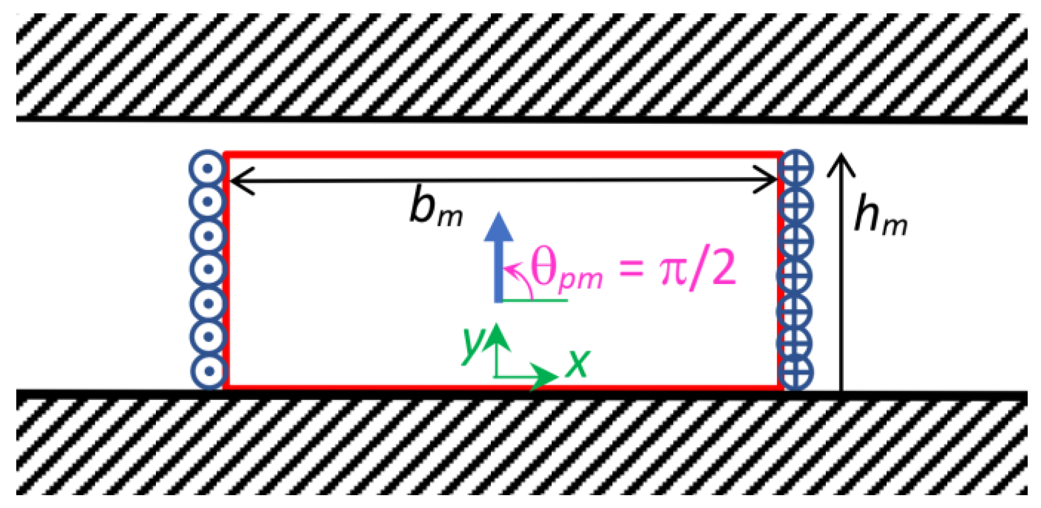
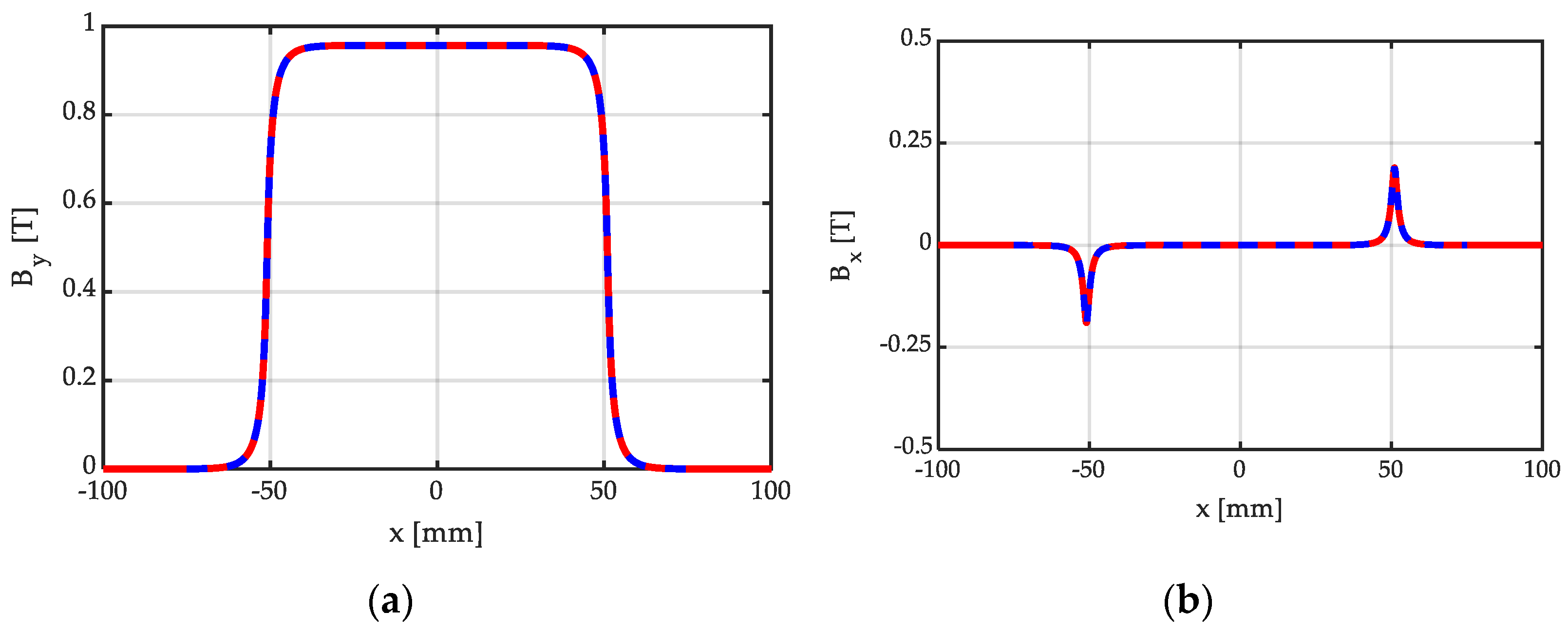
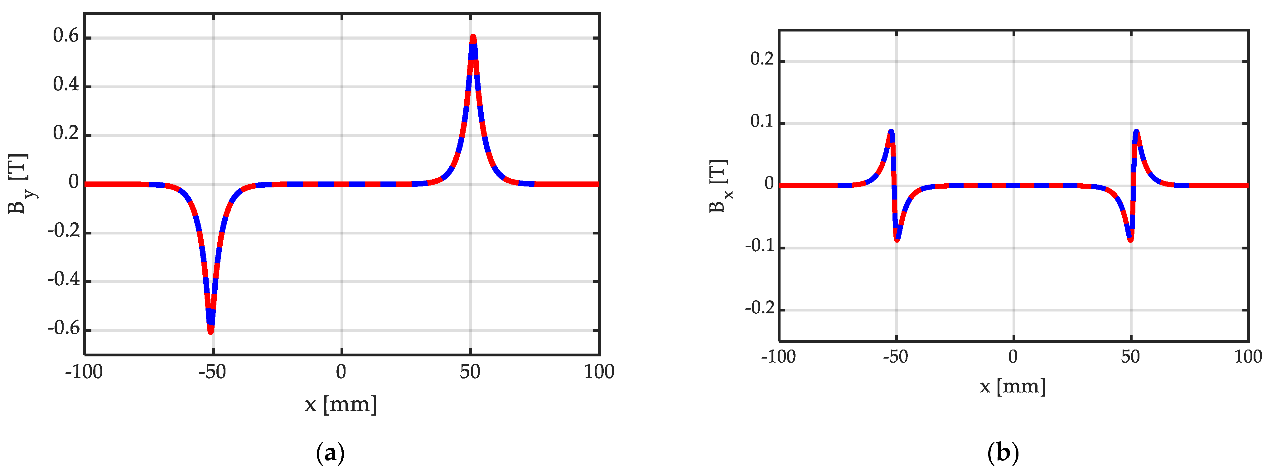
| 1 | Single permanent magnet, centred with respect to the origin, with magnetization orientated normally to the iron surfaces (as depicted in Figure 4 and Figure 5) |
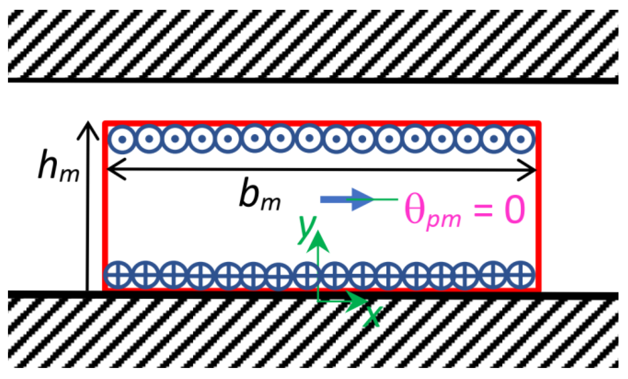
| 2 | Single permanent magnet centered in the origin, with tangential magnetization with respect to the iron surfaces (as depicted in Figure 6 and Figure 7) |
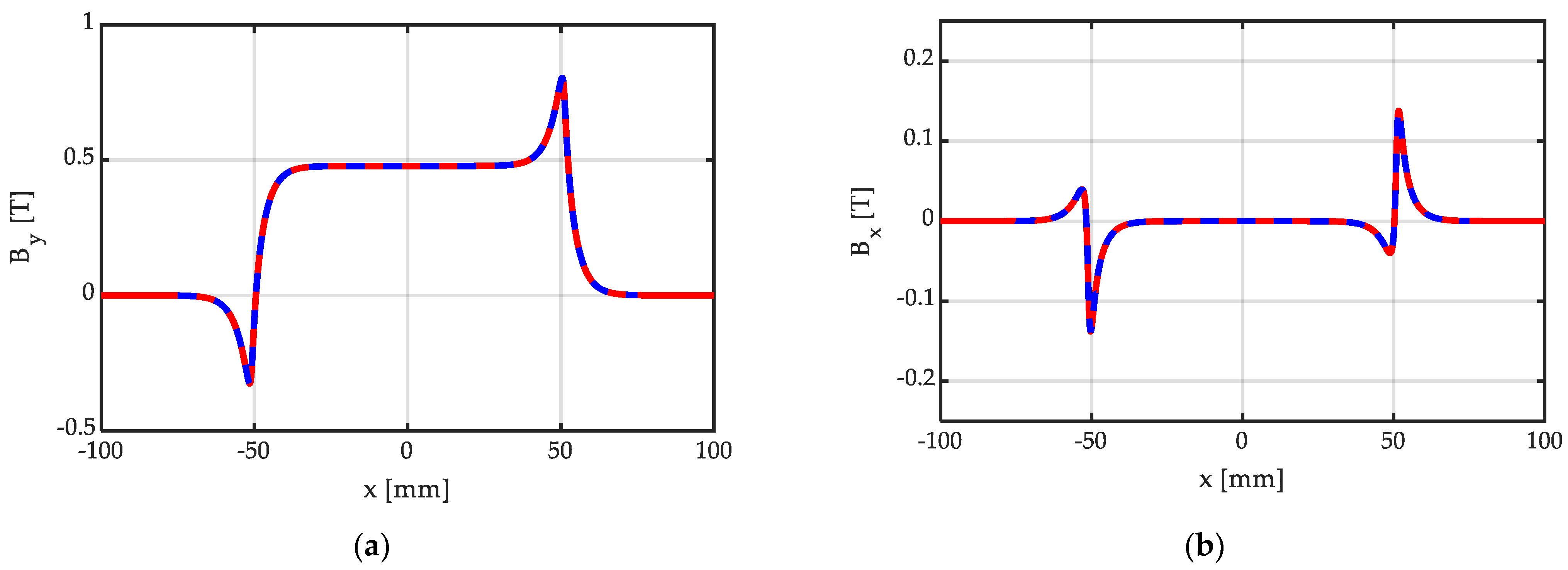
| 3 | Single Halbach permanent magnet segment with magnetization vector orientated according to an angle θpm = 30° with respect to the x axis (as depicted in Figure 8 and Figure 9) |
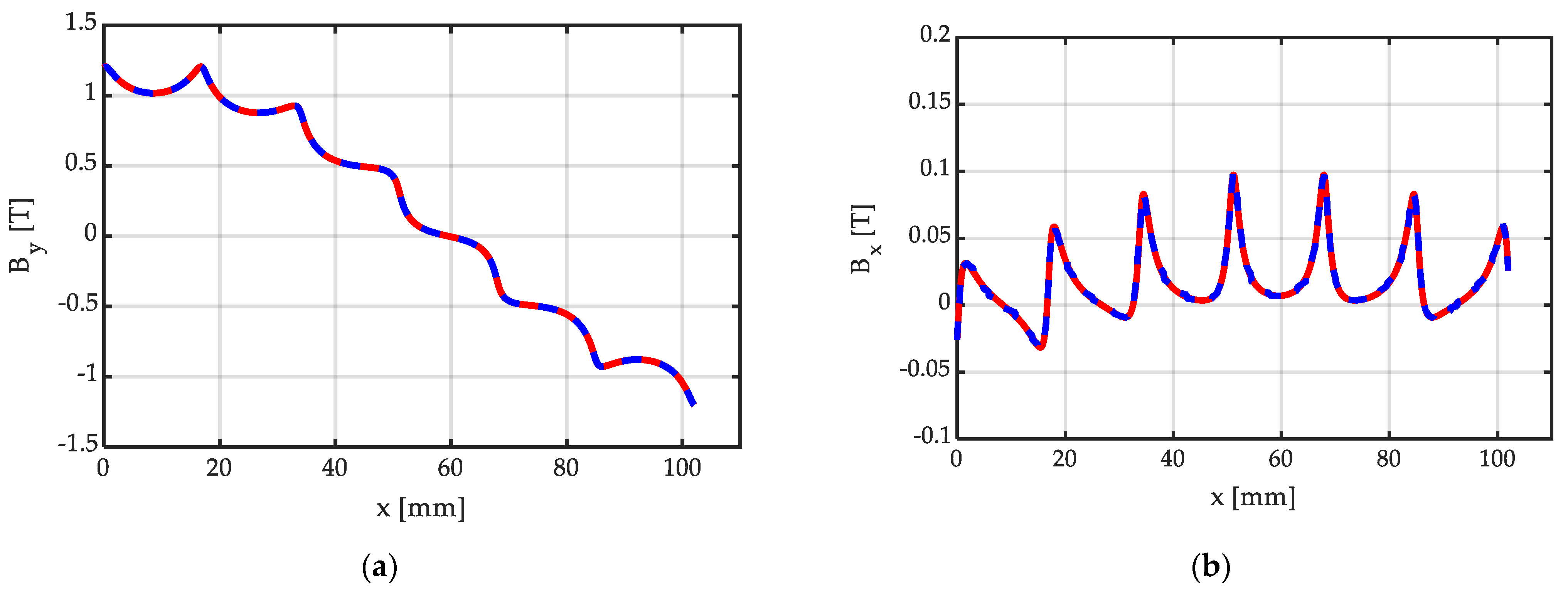
| 4 | Halbach array with Nsp = 6 segments/pole, with the same peripheral width bm (as depicted in Figure 11 and Figure 12); two Halbach arrays at the left and at the right of the central array, for a total of five Halbach arrays |
| 5 | Halbach array with Nsp = 10 segments/pole, with the same peripheral width bm (as depicted in Figure 13 and Figure 14); two Halbach arrays at the left and at the right of the central array, for a total of five Halbach arrays |
| Case N° | Analytical Calculation | FEM Calculation | Δt Ratio | |||
|---|---|---|---|---|---|---|
| Data | Data | |||||
| Calculation Time ΔtA [s] | Iterations N° | Energy Error [%] | Mesh Triangles N° | Computational Time ΔtF [s] | Comp. Times Ratio ΔtA/ΔtF [%] | |
| 1 | 0.12 | 8 | 3.21 × 10⁻⁴ | 4.99 × 10⁴ | 20 | 0.58 |
| 2 | 0.07 | 14 | 1.34 × 10⁻⁴ | 2.40 × 10⁵ | 67 | 0.10 |
| 3 | 0.08 | 13 | 1.36 × 10⁻⁴ | 1.86 × 10⁵ | 66 | 0.13 |
| 4 | 0.20 | 12 | 3.08 × 10⁻⁴ | 4.95 × 10⁴ | 18 | 1.11 |
| 5 | 0.27 | 12 | 3.77 × 10⁻⁴ | 4.80 × 10⁴ | 16 | 1.68 |
Disclaimer/Publisher’s Note: The statements, opinions and data contained in all publications are solely those of the individual author(s) and contributor(s) and not of MDPI and/or the editor(s). MDPI and/or the editor(s) disclaim responsibility for any injury to people or property resulting from any ideas, methods, instructions or products referred to in the content. |
© 2023 by the authors. Licensee MDPI, Basel, Switzerland. This article is an open access article distributed under the terms and conditions of the Creative Commons Attribution (CC BY) license (https://creativecommons.org/licenses/by/4.0/).
Share and Cite
Di Gerlando, A.; Negri, S.; Ricca, C. A Novel Analytical Formulation of the Magnetic Field Generated by Halbach Permanent Magnet Arrays. Magnetism 2023, 3, 280-296. https://doi.org/10.3390/magnetism3040022
Di Gerlando A, Negri S, Ricca C. A Novel Analytical Formulation of the Magnetic Field Generated by Halbach Permanent Magnet Arrays. Magnetism. 2023; 3(4):280-296. https://doi.org/10.3390/magnetism3040022
Chicago/Turabian StyleDi Gerlando, Antonino, Simone Negri, and Claudio Ricca. 2023. "A Novel Analytical Formulation of the Magnetic Field Generated by Halbach Permanent Magnet Arrays" Magnetism 3, no. 4: 280-296. https://doi.org/10.3390/magnetism3040022
APA StyleDi Gerlando, A., Negri, S., & Ricca, C. (2023). A Novel Analytical Formulation of the Magnetic Field Generated by Halbach Permanent Magnet Arrays. Magnetism, 3(4), 280-296. https://doi.org/10.3390/magnetism3040022


