Abstract
In 1971, Chua defined an ideal memristor that links magnetic flux φ and electric charge q. In a magnetic lump with a current-carrying conductor, we found that the direct interaction between physical magnetic flux φ and physical electric charge q is memristive by nature in terms of a time-invariant φ-q curve being nonlinear, continuously differentiable and strictly monotonically increasing. Although we succeeded in demonstrating that the “ideal/real/perfect/… memristor” needs magnetism, the structure still suffers from two serious limitations: 1. a parasitic “inductor” effect and 2. bistability and dynamic sweep of a continuous resistance range. Then, we discussed how to overcome these two limitations to make a fully functioning ideal memristor with multiple or an infinite number of stable states and no parasitic inductance. We then gave a number of innovations to the current memristor structure, such as an “open” structure, nanoscale size, magnetic materials with cubic anisotropy (or even isotropy) and sequential switching of the magnetic domains. Contrary to the conjecture that “an ideal memristor may not exist or may be a purely mathematical concept”, we remain optimistic that an ideal memristor will be discovered in nature or will be made in the laboratory. Our finding of the memristive flux–charge interaction may advance the development and application of the memristor technology.
1. Introduction
Chua defined the ideal memristor in 1971, which directly interacts with physical magnetic flux φ and physical electric charge q [1], analogous to the resistor, which directly interacts with physical voltage and physical current; the capacitor, which directly interacts with physical voltage and physical charge; and the inductor, which directly interacts with physical current and physical flux.
In 2008, HP made a memristor in titanium dioxide, in which the dopants tend to drift in the direction of the current [2]. Such mobility makes a memristor change resistance. However, from a rigorous theoretical physics perspective, the HP memristor is too incomplete (no magnetic flux), too complex (a “sandwich” structure) and too specialised (even a chemical reaction in the memory-holding oxygen vacancies) to be fundamental.
The major concern is that the HP memristor lacks a magnetic flux term in the original memristor definition. Williams from HP thought the actual definition of memristance would be more general. Williams argued, “Linking electric charge and magnetic flux is one way to satisfy the definition, but it’s not the only one. In fact, it turns out you can bypass magnetic interaction altogether.” [3].
Can we truly bypass magnetic interaction to define a memristor?
Unfortunately, thus far, it has been somewhat popular to define “φ” and “q” in a purely mathematical way without giving “φ” and “q” any physical interpretations: “φ” was defined as the time integral of voltage “v” and “q” was defined as the time integral of current “i”. Most people simply “abused” Chua’s suggested fingerprint [4]. “If it (the v-i hysteresis loop) is pinched, it is a memristor” by ignoring its prefixing (from an experimental perspective) and its context (“This definition greatly broadens the scope of memristive devices… into three classes: Ideal Memristors, Generic Memristors, and Extended Memristors.”) [4].
At least three examples can be given to demonstrate that it is highly risky to define a memristor along the v-i plane.
The first example is indefinite integration itself. Starting from v, we have , where C is an arbitrary constant [meaning that any value for C makes a valid antiderivative of v(t)]. This constant expresses an ambiguity inherent in the construction of integration; there is an indefinite number of antiderivatives of v(t), and therefore, a given v-i curve (as postulated by Chua [1], i is a pinched hysteresis loop (looking like a diagonal “∞”)) cannot uniquely determine the φ-q curve, as shown in the inset of Figure 1.
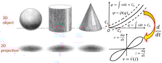
Figure 1.
Conformal differential transformation is similar to 3D object projection in terms of projecting something from a “high-dimensionality” space into a “low-dimensionality” space.
In other words, the φ-q plane is a space with “high-dimensionality” (if the charge–flux relationship of a memristor is a high-order polynomial as imagined by Chua [5]), whereas the v-i plane is its “dimensionality-reduced” space. Conformal differential transformation [4,5] projecting the φ-q curve onto the v-i plane just plays the role of dimensionality reduction (e.g., ). Imagine that we are shining a light from above a 3D object and looking at the shadow it casts on a 2D screen. The transformation from 3D to 2D is unique, but the opposite is not; we cannot work out whether the original 3D object is a ball, cylinder or cone when the 2D projection viewed is a circle. A schematic (Figure 1) best illustrates this. We cannot simply restore the lost information in the projection in a single “anti-projection”.
The second example is that, as shown in Figure 2, no hysteresis can be seen in the v-i curve if the φ-q curve is odd-symmetric, although it complies with all the three criteria [1] for the ideal memristor’s φ-q curve: 1. nonlinear, 2. continuously differentiable and 3. monotonically increasing. The φ-q curve projects to the corresponding v-i curve via the so-called conformal differential transformation (for a periodic input current): obtain the angle of incline α of the tangent line at an operating point in the curve and draw a straight line through the origin on the v-i plane whose angle of incline is also α.
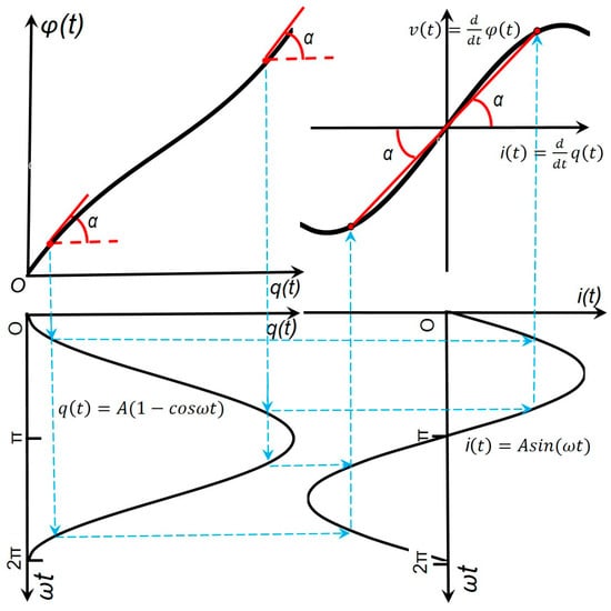
Figure 2.
No hysteresis can be seen in the v-i curve for an ideal memristor with an odd-symmetric φ-q curve.
The third example is that, as shown in Figure 3, a pinched v-i curve that is asymmetric results from even a double-valued φ-q curve, which indicates that the corresponding memristor is not ideal at all. It is concluded that an ideal memristor that is originally defined on the constitutive φ-q plane should not be characterized on the v-i plane.
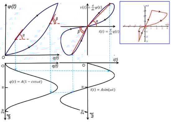
Figure 3.
A nonideal memristor even has a pinched v-i hysteresis loop. This memristor has two φ-q characteristic branches, each of which is chosen depending on the polarity of the input current. Some practical devices exhibit such q–φ curves [6].
What we have observed from the above three examples is that “even if it’s pinched it may not be an ideal memristor”. In our opinion, it is bad to define the ideal memristor on the v-i plane, it is worse to have no physical magnetic flux, and it is even worse to pretend to have a magnetic flux that is virtual and calculated from other physical attributes. Strictly speaking, it is incorrect to bypass or replace the direct, physical charge–flux interaction with a “virtual” interaction between the charge (that is normally physical, e.g., oxygen vacancies as ionic current in the HP memristor [2]) and the integral over the voltage (having no choice due to the lack of magnetic flux).
Other sceptics have also expressed a similar concern regarding the lack of a charge–flux interaction in the HP memristor. As mentioned in the same issue of IEEE Spectrum, as early as in 2009, sceptics have argued that the HP memristor is not a fourth fundamental circuit element but an example of bad science [7]. In 2015, Vongehr even declared, “The Missing Memristor Has Not Been Found” (the title of their Nature Scientific Reports paper) in the sense that an ideal memristor device should be grounded in fundamental symmetries of basic physics, here electromagnetism and that the “ideal/real/perfect/… memristor” needs magnetism [8]. It is worth mentioning that Vongehr’s work [8] is only one facet of the opposition to the ideality of a new passive fundamental electrical component. In 2017, Sundqvist, et al. showed that the claim that the present memristor functions describe a passive device violates the second law of thermodynamics in many cases [9,10]. In 2018, Abraham proposed a case to reject the memristor as a fundamental circuit element [11]. In 2022, Kim, et al. refuted the claim that all resistance-switching memories are memristors and doubted the existence of ideal memristors as actual physical devices that can be fabricated experimentally [12].
2. Magnetic Lump with Flux–Charge Interaction
In order to design an artificial device with a direct interaction between physical magnetic flux and physical electric charge and then prove that the interaction is memristive, the first principles originating from Aristotelians more than 2300 years ago may help. That is to say, we should start directly at the level of the established memristor concept based on physical charge and physical flux without making any assumption such as an empirical model (e.g., a pinched hysteresis voltage–current loop) and parameter fitting (e.g., voltage as a derivative of flux and current as a derivative of the charge).
After numerous failures, the structure in Figure 4 was eventually designed to introduce a direct charge–flux interaction. Through the conductor that carries a current and the magnetic lump that hosts magnetization, the amount of the charge can be controlled by the time interval of the current flow. The flux can be adjusted by the magnetization rotation. In order to pick up a signal from the charge–flux coupling, this conductor can simultaneously play two roles; on the one hand, it carries a current to switch the magnetization in the lump, and on the other hand, it can also sense the voltage possibly induced by the switched flux.
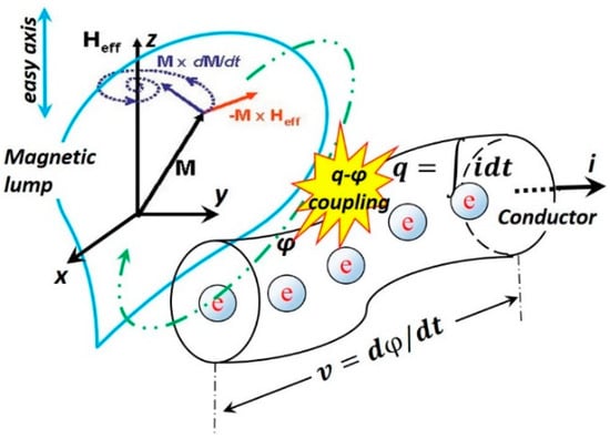
Figure 4.
The flux–charge interaction in a structure with a magnetic lump and a current-carrying conductor. The Oersted field generated by the current i rotates or switches the magnetization M inside the magnetic lump, and consequently, the switched magnetic flux φ induces a voltage v across the conductor, resulting in a changed (equivalent) memristance. The LLG model of flux reversal is also shown. If the magnetic field Heff is applied in direction Z, the saturation magnetization vector M(t) follows a precession trajectory from its initial position () until (), i.e., the magnetization M(t) reverses itself and is eventually aligned with the magnetic field Heff.
3. LLG Model of Magnetic Flux Reversal
The resulting equivalent resistance, the ratio between the sensed voltage and the driving current, of the above structure is possibly memristive. It would be highly unlikely that it would have a linear charge–flux interaction due to the existence of magnetic material with rich hysteresis. That is, it is the magnetic lump material that may provide a source of nonlinearity necessary for such a structure.
In order to describe the charge–flux interaction in a mathematically and physically rigorous way, the Landau–Lifshitz–Gilbert equation [13,14] was used. Assuming , in which MZ is the component of the saturation magnetization MS in the Z axis, and a magnetic field H is applied along Z. The model is expressed as below:
in which SW is a switching coefficient, and C is a constant of integration such that (m0 is the initial value of m) if q(t = 0) = 0 (no accumulation of charge at any point).
By Faraday’s law, the induced voltage v(t) is
where μ0 is the permeability of free space and S is the cross-sectional area.
From Equation (2), we obtain
where is another constant of integration.
Assuming , we have ; so,
Equation (4) complies with the three new criteria [6] for the ideal memristor: 1. nonlinear; 2. continuously differentiable; and 3. strictly monotonically increasing. Figure 5 shows a typical φ-q curve with m0 = −0.964 (such a value reflects the intrinsic fluctuation; otherwise, M will stick to the stable equilibriums ).
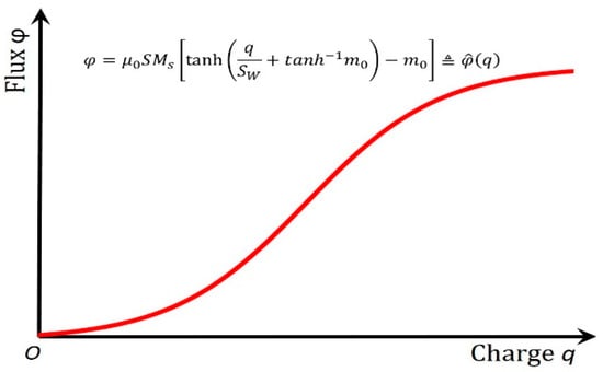
Figure 5.
Intuitively, the S-shaped φ-q curve (Equation (4)) of this structure vividly depicts the self-limiting charge–flux interaction in a circuit element. It complies with the three new criteria for the ideal memristor [1,6]: a. nonlinear; b. continuously differentiable; c. strictly monotonically increasing.
Figure 5 agrees with those experimentally observed φ-q curves in the magnetic cores [15,16,17]. Therefore, Equation (4) is used as a constitutive curve in this work. The constitutive curve in Figure 4 is dramatically different from that of Chua’s “fictitious” memristor with a charge–flux relationship in his tutorial [5]. We have for a hyperbolic function whose output range is normalized from −1 to 1 (no matter how big the input is), whereas we have for a polynomial function (that diverges to infinity). In other words, such a structure’s operation range is finite (where ), whereas the “fictitious” memristor’s range is infinite. Such a self-limiting hyperbolic tangent function is more natural than other functions since the S curve approaches 1 as x is +∞ and approaches zero as x is −∞. In biology and ecology, a self-limiting colony of organisms limits its own growth by its actions (releasing waste that is toxic to the colony once it exceeds a certain population) [18]. In this instance, there is a clear physical explanation for the saturation of this structure: it is because the magnetization vector is as aligned as the magnetic field allows it to be. The change in the magnetization alignment is negligible on increasing the field above this.
If a step-function excitement current is applied and its rise time is short enough in approaching constant I, by Faraday’s law, the induced voltage is
Equation (5) is depicted in Figure 6.
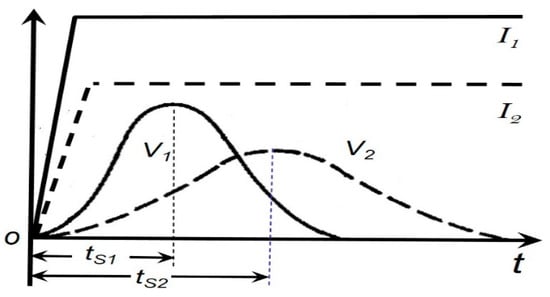
Figure 6.
Induced voltage vs. a step-function input current. The higher the amplitude of the current I, the shorter the switching time ts.
From Equation (4), the memristance M(q) of our memristor is
4. Parasitic Inductance and Stepwise Memristance
Inevitably, parasitic inductance of this structure in Figure 4 coexists, especially if it is a core with a high coupling efficiency (Figure 7), which can be described by
where L is the inductance (mH) of the magnetic core, is the cross-sectional area of the core, is the average length of the core, μ is the permeability of the core, N is the number of the turns in the coil (N = 1 in Figure 4), D (cm) is the outer diameter of the core, d (cm) is the inner diameter of the core, and h (cm) is the height of the core [19].
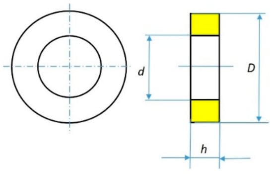
Figure 7.
Geometry of a magnetic core for the inductance calculation.
If a fixed aspect ratio D = 2d = 2h is taken, Equation (5) can be simplified to
which implies that the inductance of a magnetic core scales with its physical size. This is truly encouraging in the sense that, in principle, an ideal memristor at the nanoscale is expected to have negligible parasitic inductance.
Notably, as shown in Equation (6), the parasitic inductance in this device is not a function of the charge (otherwise, it will become a mem-inductor [20,21]), whereas its resistance (memristance) is a function of the charge.
An antiferromagnet/ferromagnet heterostructure [22] was found to exhibit a stepwise memristance (due to the sequential switching of the domains in the ferromagnetic layer), in which one can freeze the resistance statically at any intermediate time point. It exhibits a continuous “state-dependent Ohm’s law” and provides a solution of Chua’s Enigma: All non-volatile memristors have continuum memories [23]. Pershin, Di Ventra and Kim designed a test to check experimentally if a resistor with memory is indeed a memristor, in terms of its resistance depending only on the charge that flows through it or on the history of the voltage across it [24,25,26].
5. Conclusions and Arguments
Our innovative work represents a step forward in terms of verifying the memristive charge–flux interaction, but we have not reached the final The structure has two serious limitations:
- The aforementioned memristive fingerprint hides behind a superficial inductor effect due to its inductor-like structure. It was necessary to apply a constant input current (such as a step-function or a sequence of square-wave pulses) to depress the inductor effect (). Despite the existence of parasitic inductance, the structure displays memristivity; similarly, a real-world resistor is still thought to be a resistor despite the existence of an (inevitable) parasitic inductance and/or capacitance. Most importantly, the structure exhibits that its charge–flux interaction is memristive by nature.
- The structure is bistable and dynamically sweeps a continuous range of resistances. This “dynamical continuity” results from the uniaxial magnetic anisotropy of the prototype, which contains magnetic material with only one easy axis. A fully functioning ideal memristor should have multiple or an infinite number of stable states so its static memristance can be “frozen” at any intermediate point in time.
Limitation 2 (“dynamic continuity”) may be overcome by using magnetic materials with cubic anisotropy (three or four easy axes as shown in Figure 8 [27]) or even a magnetically isotropic material (no preferential direction for its magnetisation) [28]. In addition, an antiferromagnet/ferromagnet heterostructure exhibits stepwise memristance due to sequential switching of the domains in its ferromagnetic layer [22]. However, this bilayer is nonideal since its resistance is a function of several internal state variables, including temperature, and it is not a function of only charge [22].
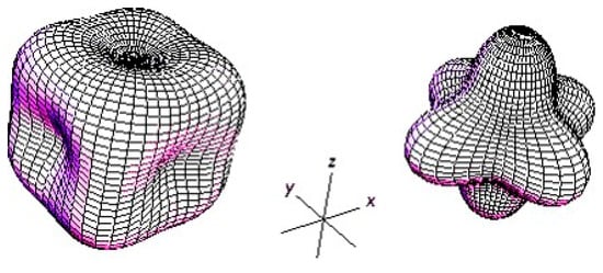
Figure 8.
Cubic anisotropy energy surfaces. The magnetic moment in cobalt has a dependence of energy level towards one particular direction (the easy axis); then, it has uniaxial anisotropy. The biases in iron (left) and nickel (right) are toward many particular directions; then, they have multiple easy axes and possess cubic anisotropy [27].
A fully functioning charge–flux-interaction-based ideal memristor with multiple or an infinite number of stable states and no parasitic inductance is still highly in demand in terms of filling the gap of 50 years [1,7,8] and advancing the development and application of memristor technology. The existence of such a fundamental circuit element may appeal to many researchers in the memristor field within the context of the theoretical circuit innovations that depend on charge–flux linkage [28,29,30,31,32]. We are still optimistic that researchers will discover an ideal memristor in nature or make one in the laboratory, although some researchers feel that an ideal memristor may not exist or may be a purely mathematical concept [25].
Funding
This research was partially funded by an EC grant “Re-discover a periodic table of elementary circuit elements”, PIIFGA2012332059, Marie Curie Fellow: Leon Chua (UC Berkeley), Scientist-in-charge: Frank Wang (University of Kent).
Data Availability Statement
All data generated and analyzed during this study are included in this published article.
Conflicts of Interest
The authors declare no conflicts of interest. The funders had no role in the design of the study; in the collection, analyses, or interpretation of data; in the writing of the manuscript; or in the decision to publish the results.
References
- Chua, L. Memristor—The Missing Circuit Element. IEEE Trans. Circuit Theory 1971, 18, 507–519. [Google Scholar] [CrossRef]
- Strukov, D.; Snider, D.; Stewart, S.; Williams, S. The missing memristor found. Nature 2008, 453, 80–83. [Google Scholar] [CrossRef]
- Williams, R.S. How we found the missing memristor. IEEE Spectr. 2008, 45, 29–35. [Google Scholar] [CrossRef]
- Chua, L. If it’s pinched it’s a memristor. Semicond. Sci. Tech. 2014, 29, 104001. [Google Scholar] [CrossRef]
- Chua, L. Resistance switching memories are memristors. Appl. Phys. A 2011, 102, 765–783. [Google Scholar] [CrossRef]
- Georgiou, P.S.; Barahona, M.; Yaliraki, S.N.; Drakakis, E.M. On memristor ideality and reciprocity. Microelectron. J. 2014, 45, 1363–1371. [Google Scholar] [CrossRef]
- Adee, S. Resistance to Memristance. IEEE Spectr. 2008, 45, 34. [Google Scholar] [CrossRef]
- Vongehr, S.; Meng, X. The missing memristor has not been found. Nat. Sci. Rep. 2015, 5, srep11657. [Google Scholar] [CrossRef]
- Sundqvist, K.M.; Ferry, D.K.; Kish, L.B. Memristor Equations: Incomplete Physics and Undefined Passivity/Activity. Fluct. Noise Lett. 2017, 16, 1771001. [Google Scholar] [CrossRef]
- Sundqvist, K.M.; Ferry, D.K.; Kish, L.B. Second Law based definition of passivity/activity of devices. Phys. Lett. A 2017, 381, 3364–3368. [Google Scholar] [CrossRef][Green Version]
- Abraham, I. The case for rejecting the memristor as a fundamental circuit element. Sci. Rep. 2018, 8, 10972. [Google Scholar] [CrossRef]
- Kim, J.; Pershin, Y.; Yin, M.; Datta, T.; Di Ventra, M. A Definitive Demonstration that Resistance-Switching Memories Are Not Memristors. Available online: http://nvmw.ucsd.edu/nvmw2022-program/nvmw2022-data/nvmw2022-paper1-final_version_your_extended_abstract.pdf (accessed on 27 June 2024).
- Landau, L.D.; Lifshitz, E.M. Theory of the dispersion of magnetic permeability in ferromagnetic bodies. Physik. Z. Sowjetunion 1935, 8, 153–169. [Google Scholar]
- Gilbert, T.L. A Lagrangian formulation of the gyromagnetic equation of the magnetic field. Phys. Rev. 1955, 100, 1243. [Google Scholar]
- Menyuk, N.; Goodenough, J. Magnetic materials for digital computer components. I. A theory of flux reversal in polycrystalline ferromagnetics. J. Appl. Phys. 1955, 26, 8–18. [Google Scholar] [CrossRef]
- Gyorgy, E.M. Rotational model of flux reversal in square loop ferritcs. J. Appl. Phys. 1957, 28, 1011–1015. [Google Scholar] [CrossRef]
- Cushman, N. Characterization of Magnetic Switch Cores. IRE Trans. Compon. Parts 1961, 8, 45–50. [Google Scholar] [CrossRef]
- Available online: https://en.wikipedia.org/wiki/Self-limiting_(biology) (accessed on 27 June 2024).
- Approximate Inductance of a Toroid. Available online: http://hyperphysics.phy-astr.gsu.edu/hbase/magnetic/indtor.html (accessed on 25 June 2024).
- Di Ventra, M.; Pershin, Y.V.; Chua, L.O. Memristive circuits simulate memcapacitors and meminductors. Proc. IEEE 2009, 97, 1717. [Google Scholar] [CrossRef]
- Wang, F.Z. Beyond Memristors: Neuromorphic Computing Using Meminductors. Micromachines 2023, 14, 486. [Google Scholar] [CrossRef] [PubMed]
- Kurenkov, A.; DuttaGupta, S.; Zhang, C.; Fukami, S.; Horio, Y.; Ohno, H. Artificial Neuron and Synapse Realized in an Antiferromagnet/Ferromagnet Heterostructure Using Dynamics of Spin–Orbit Torque Switching. Adv. Mater. 2019, 31, e1900636. [Google Scholar] [CrossRef]
- Chua, L. Five non-volatile memristor enigmas solved. Appl. Phys. A 2018, 124, 563. [Google Scholar] [CrossRef]
- Pershin, Y.V.; Kim, J.; Datta, T.; Di Ventra, M. An experimental demonstration of the memristor test. arXiv 2021, arXiv:2102.11963. [Google Scholar] [CrossRef]
- Kim, J.; Pershin, Y.V.; Yin, M.; Datta, T.; Di Ventra, M. An experimental proof that resistance-switching memory cells are not memristors. Adv. Electron. Mater. 2020, 6, 2000010. [Google Scholar] [CrossRef]
- Pershin, Y.V.; Di Ventra, M. A simple test for ideal memristors. J. Phys. D Appl. Phys. 2018, 52, 01LT01. [Google Scholar] [CrossRef]
- Aharoni, A. Introduction to the Theory of Ferromagnetizm, 2nd ed.; Clarendon Press: London, UK, 1996; pp. 330–336. [Google Scholar]
- Biolek, D.; Vavra, J.; Biolek, Z.; Kolka, Z.; Biolkova, V.; Dobes, J. Chua’s Table as a Tool for Constructing Dual Networks. In Proceedings of the 2019 IEEE Asia Pacific Conference on Circuits and Systems (APCCAS), Bangkok, Thailand, 11–14 November 2019. [Google Scholar]
- Biolek, D.; Biolek, Z.; Biolkova, V.; Kolka, Z. X-Controlled Memristive Devices for Automatic Gain Control in RC Oscillators. In Proceedings of the 2020 New Trends in Signal Processing, Demanovska Dolina, Slovakia, 14–16 October 2020. [Google Scholar]
- Eshraghian, J.K.; Cho, K.-R.; Iu, H.H.C.; Fernando, T.; Iannella, N.; Kang, S.-M.; Eshraghian, K. Maximization of crossbar array memory using fundamental memristor theory. IEEE Trans. Circuits Syst. II Express Briefs 2017, 64, 1402–1406. [Google Scholar] [CrossRef]
- Eshraghian, J.K.; Iu, H.H.; Fernando, T.; Yu, D.; Li, Z. Modelling and characterization of dynamic behavior of coupled memristor circuits. In Proceedings of the 2016 IEEE International Symposium on Circuits and Systems (ISCAS), Montreal, QC, Canada, 22–25 May 2016. [Google Scholar]
- Chua, L. Everything You wish to know about memristors but are afraid to ask. In Handbook of Memristor Networks; Springer: Berlin/Heidelberg, Germany, 2019. [Google Scholar]


Disclaimer/Publisher’s Note: The statements, opinions and data contained in all publications are solely those of the individual author(s) and contributor(s) and not of MDPI and/or the editor(s). MDPI and/or the editor(s) disclaim responsibility for any injury to people or property resulting from any ideas, methods, instructions or products referred to in the content. |
© 2024 by the author. Licensee MDPI, Basel, Switzerland. This article is an open access article distributed under the terms and conditions of the Creative Commons Attribution (CC BY) license (https://creativecommons.org/licenses/by/4.0/).