Abstract
Steel components in the boilers of nuclear reactors are subject to high temperatures and varying loading conditions. This can introduce time-dependent and time-independent plasticity, which can interact with one another. Specimens of 316H austenitic stainless steel were heated to 550 °C and tensile pre-strained to 8%, 11% and 14% followed by 200 h, 280 MPa creep tests. These tests showed an increase in creep resistance with increasing tensile pre-strain. Macroscale simulations using RCC-MR deformation laws proved ineffective at predicting this interaction. Microscale crystal plasticity simulations proved effective at predicting the trends observed experimentally, hence demonstrating the potential of crystal plasticity as a predictive tool for structural integrity analysis.
1. Introduction
The fleet of civil power Advanced Gas Cooled (nuclear) Reactors (AGRs) in the United Kingdom, operated by EDF Energy, are entering their end-of-life phase having operated for several decades. These reactors contain a graphite moderated core cooled by carbon dioxide gas. Of key interest are the steel components within the boilers, which experience peak temperatures ranging from 480 °C to 650 °C [1]. Due to the constrained nature of these components and the stresses they experience, plastic deformation can occur. Plastic deformation influences the subsequent creep behaviour exhibited [2]. More effective models can be developed by improving our understanding of creep and its interaction with plasticity. These models can aid in structural integrity analysis, thus assisting the AGR life extension program currently under operation.
This research explores the effect of prior, high plasticity, tensile deformation on the subsequent creep response of 316H austenitic stainless steel. Previous research has shown a variety of effects of prior plasticity on creep. Both an increase [3,4] and decrease [5] in creep resistance have been observed. Alongside this, small amounts of reverse inelastic plasticity have been shown to ‘reset’ creep response and allowed further primary creep accumulation [6]. This is known under several terms, such as primary creep regeneration (PCR). By comparing the experimental results with those of mesoscale and macroscale finite element simulations, the strengths and weaknesses of each can be determined; hence, areas of further development can be identified.
2. Materials and Methods
Specimens of 316H were tensile pre-strained to 8%, 11% and 14% at 550 °C. Subsequent 200 h creep tests were performed at 280 MPa. Creep rates were subsequently calculated in order to quantify the effect of tensile pre-strain on creep resistance. Finite element simulations at the macro- and micro-scale were performed to demonstrate the predictive capability of these two models.
2.1. Material
Type 316H stainless steel has been selected for this study due to its use in boiler components in AGRs [1]. 316H is an austenitic stainless steel with a face centred cubic (FCC) crystal structure. The specific cast of 316H was manufactured by ELG Carrs Stainless Steel and selected by EDF due to its similar chemical composition of 316H used in current reactors. This cast has been internally dubbed ELG and hence will be referred to as such in the following work. A summary of the chemical composition of this can be found in Table 1, in which it is compared to a cast of ex-service 316H.

Table 1.
Chemical composition of ELG and ex-service material (wt%). Both materials are different casts of 316H austenitic stainless steel.
2.2. Specimen Design
The specimens used for this experimental work were cylindrical with a diameter and gauge length of 6 mm and 36 mm, respectively, threaded at both ends. The ratio of gauge length to diameter was selected as 1:6 to increase the accuracy of strain measurement, in accordance with ASTM E139 guidelines [7].
2.3. Test Setup
Experimental work has been performed using a Zwick Roell Kappa SS-CF (Ulm, Germany), an electromechanical fatigue testing machine capable of loading up to 100 kN, although less than 10 kN was applied for these experiments. A furnace was used to heat the specimens up to 550 °C and maintain this temperature for 200+ h. Two Type N thermocouples were used to measure the surface temperature of the specimen at the top and bottom of the gauge length. The results from the thermocouples showed that the specimen temperature varied by ±0.7 °C. A small opening where the two sides of the furnace close allowed the attachment of the two extensometers used. One extensometer was used to measure the tensile pre-strain and another extensometer used to measure the creep strain. Ideally, one extensometer would have been used for all strain measurements. However, the maximum strain range of 8%, of the ideal extensometer, would have resulted in an inaccurate measure of strain beyond this point; hence, an additional extensometer was used to measure the pre-strain due to its higher strain range. Images of the experimental setup can be found in Figure 1.
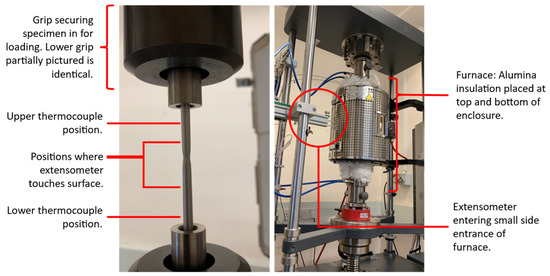
Figure 1.
Labelled diagram of the experimental setup, highlighting sample installation and furnace enclosure. The specimen shown is from a previous experiment but serves the purpose of setup description effectively.
Following the installation of the specimen in the testing machine, the specimen was held under a force of 10 N whilst being heated. Force control was used to prevent stress relaxation. Heating introduces approximately 1.1% thermal strain. This did not need to be accounted for when using the first extensometer as this was attached after heating and soaking (1.5 h). For the second extensometer, the separation of the prongs was set to an equivalent of −1.1% strain at room temperature. Therefore, at 550 °C, the reading was 0% strain.
2.4. Testing Regime and Procedure
For each specimen, an identical procedure was applied. The specimen was heated from room temperature to 550 °C. An extensometer was attached and the specimen pre-strained under constant strain rate ( s−1). Following this, the specimen was unloaded to 10 N and subsequently cooled to room temperature. The second extensometer was then installed. The specimen was then re-heated and loaded elastically to a stress lower than that of the pre-strain and held for a 200 h creep test. Figure 2 summarises this diagrammatically.
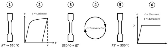
Figure 2.
Summary of the experimental regime each specimen was subjected to. A more detailed description can be found in the first paragraph of Section 2.4.
The testing matrix can be found in Table 2. The reasons for the levels of pre-strain are twofold. An interest in high plastic strains that could potentially accumulate in reactors. Previous experimental work has identified ELG as being creep-resistant. Forward creep tests at 260, 280 and 320 MPa have shown creep accumulation of approximately 0.05%, 0.19% and 0.09%, respectively, after 200 h. This small strain accumulation at large stresses indicates that performing creep tests at a stress lower than 260 MPa (at 550 °C) may not provide measurable amounts of strain in a 200 h window. Therefore, pre-strains above the 280 MPa stress level were used such that creep tests can be performed at this stress, where measurable creep strain has been observed. Creep data from the specimen with tensile pre-strain of 0% were obtained from previous internal experimentation.
Table 2.
Testing regime for determining effect of high-temperature plastic pre-strain on subsequent creep rate.
3. Results and Discussion
3.1. Specimen Loading
Figure 3 highlights loading curves of three specimens of ELG at 550 °C. The elastic modulus calculated is 163 ± 2 GPa and a yield (0.2% proof) stress of 134 ± 3 MPa. These results are similar to previous experimental findings, although the yield stress is slightly lower. This may be due to the 316H in the literature being ex-service steel; hence, it may have hardened throughout its lifetime [8]. The noise observed in these curves is predominantly a result of dynamic strain ageing (DSA): plastic flow instability at high temperature.
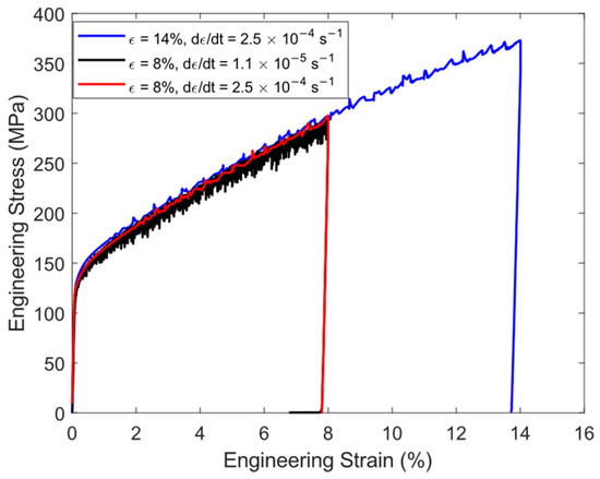
Figure 3.
Loading curves of three specimens at 550 °C, highlighting negligible difference despite significantly different strain rates.
One specimen was loaded at a strain rate of s−1 (compared to s−1). Therefore, increasing the loading time from 5 min to 2 h, which is more aligned with loading times on a plant operation scale. There is negligible difference in these loading curves at different strain rates. This suggests that, during loading, plasticity is time independent. Hence, it can be assumed that the strain accumulated in the subsequent creep tests is predominantly time dependent plasticity.
3.2. Creep Tests
Figure 4a shows the results of the creep tests following tensile pre-strain. The data has been smoothed using a Savitzky–Golay filter due to noise observed at low strain measurements. This shows a clear trend that an increase in tensile pre-strain results in an increase in creep resistance. This can be quantified using a creep enhancement parameter, [2].
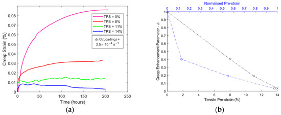
Figure 4.
(a) Creep tests of pre-strained specimens at 280 MPa. (b) Effect of pre-strain on creep rate, parameter definition included in Section 3.2.
is the average creep strain rate at a tensile pre-strain (TPS) of X% and is the average creep strain rate at a TPS of 0%. Effectively, a normalization comparing creep strain rates to a specimen that has undergone no pre-strain. If , there is an increase in creep rate with increased pre-strain. Therefore, demonstrates a decrease in creep rate with increasing pre-strain. The relationship between TPS and shows a strong linear relationship with a negative gradient, as shown by the black curve in Figure 4b. The average creep rate was calculated, as opposed to secondary creep rate, as the test on the specimen with TPS = 14% demonstrated a negative strain rate after approximately 120 h. This behaviour is not typically observed under these conditions; hence, a repeat experiment would prove beneficial to confirm this result.
Upon loading, an engineering stress of 280 MPa resulted in a strain of 7.1%. Any pre-strain put into the specimens lower than this value will have little effect on the creep rate at 280 MPa as the strain will always reach 7.1% at this stress. Therefore, in the pre-strain region 0 to 7.1% the creep enhancement parameter will be near one. This resulted in the creation of a normalized pre-strain parameter, , where
is the strain achieved when loading to the creep stress, in this case—7.1%. This allows insight into the effect of additional strain on the creep enhancement parameter (Figure 4b—blue curve). This further highlights the increasing creep resistance with additional strain; however, this relationship appears more exponential in nature. Additional experiments could be performed in the 7.1% to 8% region to clarify this.
The increasing creep resistance is likely a result of hardening of the specimens, as a result of the pre-strain. The Orowan Equation [9],
describes strain rate as a function of dislocation motion, where is the mobile dislocation density, the Burger’s vector length, b, and the average dislocation velocity, v. Plastic strain has been well documented at increasing the dislocation density in polycrystalline materials [10,11,12]. Therefore, the increased pre-straining of these specimens results in an increase in dislocation density. The mobile dislocations are not fully recovered, despite the high temperature; hence, the dislocation velocity is decreased due to the barrier created by the pre-strain dislocations. Thus, the strain rate decreases. It is important to note this is not always the case with engineering alloys, such as ferritic steels [5], but these results correlate well with previous literature of austenitic steels [2,3,4].
These creep tests were performed at constant engineering stress of 280 MPa. Due to the nature of the two loading cycles, the specimen diameter was decreased; hence, the force equivalent to 280 MPa resulted in higher true stresses. Using thermal expansion coefficients and assuming constant volume of the gauge length, the true stresses were calculated to be between 293 and 312 MPa. Creep strain rate is proportional to the stress of the creep test [2]; however, this is clearly not witnessed as the creep enhancement parameter consistently decreases with higher stress hence the hardening has dominated the effect on creep strain accumulated.
3.3. Macroscale Simulations
Finite element simulations at the macroscale were performed. The constitutive material model utilised a Young’s modulus of 205 GPa and Poisson’s ratio of 0.28 at 20 °C. To model the plastic deformation a Chaboche nonlinear isotropic/kinematic hardening law was used. The parameters used are temperature dependent which can be found in [13], alongside more detail about this model. To model the creep deformation, RCC-MR deformation laws [14,15] were utilised. These Equations provide an empirical relationship between creep strain, stress and temperature through a series of parameters.
is creep strain in %, is the Von Mises stress, t is the current time and tfp is the time at the end of primary creep. C1, C2, n1, C and n are temperature dependent material constants derived from previous experimental data of 316H and 316L. This model is highly conservative hence was a poor representation of ELG. Therefore, the model was calibrated to ELG based on previous, internal, forward creep data.
Simulations using a single cubic C3D8 element were performed to test the model’s capability of predicting the creep–plasticity interaction. The results showed that pre-strain had no impact on the subsequent creep accumulated. The only factor that altered the creep rate, at constant temperature, was the creep stress. This was expected due to the lack of a pre-strain term in Equations (4) and (5).
3.4. Microscale Simulations
Finite element simulations using a crystal plasticity (CP) based model, developed in the solid mechanics research group at the University of Bristol, have been performed to investigate whether the experimental trend is predicted by this model. These simulations were performed by utilizing a user subroutine in ABAQUS 2018. Simulations are performed utilizing representative volume elements (RVEs). In this case, this is a cube containing 23 × 23 × 23 (12,167) elements. These elements represent 97 grains which simulate the twelve slip systems of an FCC material. Microstructure data from [16] was utilized to generate this RVE. The model can incorporate calculations based on the grainsize; however, this appeared unnecessary for these simulations and hence a untextured, randomly oriented, RVE was used (depicted in Figure 5a).
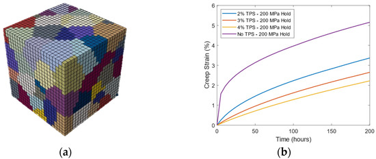
Figure 5.
(a) RVE containing 97 grains. (b) CP simulation results showing the same trend witnessed in experimentation.
CP modelling has been around for some time and the basic theory is well established [16]. It begins by separating the deformation gradient (F) into its elastic (Fe) and plastic (Fp) components,
Following further derivation, see [16], the plasticity in the system can be represented as the sum of slip across all slip systems. The slip rate () per slip system () is defined as
is the applied resolved shear stress, is the kinematic hardening term, is the initial slip resistance. and are reference strain rates for time-dependent and time-independent plasticity, respectively and and are strain-rate sensitivity exponents for time-independent and time-dependent plasticity, respectively. These power law components separate plastic and creep strain. The aforementioned paper [16] describes the CP model in much more detail although the model used for these simulations has been slightly modified.
The model was not calibrated to ELG for these simulations, this will be done in further work. These simulations were performed to determine if the experimental trends are followed. The RVE was strained 2%, 3% and 4% strain and held at a stress 200 MPa. This was performed in one cycle, unlike the experimental conditions, as the material parameters used are temperature dependent and cannot be currently altered mid-simulation. The simulations performed were strained significantly lower as the model has not been calibrated beyond this point. The simulation results are displayed in Figure 5b.
In order to calculate creep strain, a python script was utilised to calculate volume averaged strain in the loading direction of the RVE. The simulations predict the same trend as observed experimentally; increasing tensile pre strain reduces the subsequent creep rate. This provides sufficient evidence to perform further work with crystal plasticity as it can model the material response. Previous calibrations have shown good agreement with experimental data [16]. Hence, once a calibration has been performed, it will be interesting to see how well these results align.
4. Further Work
- More tests performed in this experimental strain range, particularly the 7.1% to 8% range, to further quantify the observed trend.
- Repeat tests at controlled true creep stresses to provide a clearer comparison between data sets.
- Development of the crystal plasticity simulations, specifically calibration, will determine how effectively the model can be a predictive tool.
5. Conclusions
- The high-temperature uniaxial stress–strain relationship of this cast of 316H is rate invariant over a loading time of 5 min to 2 h.
- Increasing tensile pre-strain reduces the average creep rate of this cast of 316H. The results of these experiments show that at the highest normalized pre-strain recorded (~100%), the creep rate was reduced by a factor of 10.
- The RCC-MR deformation law in combination with a non-linear isotropic/kinematic hardening law is ineffective at modelling the creep–plasticity interaction experimentally observed.
- Crystal plasticity simulations have shown that they can predict the creep–plasticity trends observed experimentally. Further calibration and simulations would prove whether this can align well with experimental data.
Author Contributions
Conceptualization, C.A.; methodology, C.A.; software, C.A.; validation, C.A.; formal analysis, C.A.; investigation, C.A.; resources, H.C. and C.T.; data curation, C.A.; writing—original draft preparation, C.A.; writing—review and editing, H.C.; visualization, C.A.; supervision, H.C. and C.T.; project administration, H.C. and C.T.; funding acquisition, H.C. and C.T. All authors have read and agreed to the published version of the manuscript.
Funding
This research was funded by EDF Energy and the UK Engineering and Physical Sciences Research Council grant number EP/S023844/1.
Institutional Review Board Statement
Not applicable.
Informed Consent Statement
Not applicable.
Data Availability Statement
All data used to draw conclusions can be found within these conference proceedings.
Acknowledgments
Specimen material was provided by EDF Energy. I would like to thank Mehdi Mokhtarishirazabad for his support, advice and training throughout the experimental process.
Conflicts of Interest
The authors declare no conflict of interest.
References
- Petkov, M.P.; Hu, J.; Cocks, A.C.F. Self-Consistent Modelling of Cyclic Loading and Relaxation in Austenitic 316H Stainless Steel. Philos. Mag. 2019, 99, 789–834. [Google Scholar] [CrossRef]
- Li, D.F.; O’Dowd, N.P.; Davies, C.M.; Nikbin, K.M. A Review of the Effect of Prior Inelastic Deformation on High Temperature Mechanical Response of Engineering Alloys. Int. J. Press. Vessel. Pip. 2010, 87, 531–542. [Google Scholar] [CrossRef]
- Ohashi, Y.; Kawai, M.; Momose, T. Effects of Prior Plasticity on Subsequent Creep of Type 316 Stainless Steel at Elevated Temperature. J. Eng. Mater. Technol. 1986, 108, 68–74. [Google Scholar] [CrossRef]
- Taylor, M.; Mamun, A.; Knowles, D. The Influence of Prior Plastic Loading on the Accumulation of Creep Strain in 316H Stainless Steel. In Proceedings of the ASME 2019 Pressure Vessels & Piping Conference, San Antonio, TX, USA, 14–19 July 2019; AMSE: New York, NY, USA, 2019. Volume 6B: Materials and Fabrication. [Google Scholar]
- Tai, K.; Endo, T. Effect of Pre-Creep on the Succeeding Creep Behavior of a 2.25Cr-1Mo Steel. Scr. Metall. Mater. 1993, 29, 643–646. [Google Scholar] [CrossRef]
- Mamun, A.A.; Simpson, C.; Agius, D.; Lee, T.L.; Kabra, S.; Truman, C.; Mostafavi, M.; Knowles, D. A Novel Insight into the Primary Creep Regeneration Behaviour of a Polycrystalline Material at High-Temperature Using In-Situ Neutron Diffraction. Mater. Sci. Eng. A 2020, 786, 139374. [Google Scholar] [CrossRef]
- ASTM E139-11(2018); Standard Test Methods for Conducting Creep, Creep-Rupture, and Stress-Rupture Tests of Metallic Materials. ASTM International: West Conshohocken, PA, USA, 2018.
- Davies, C.; Mueller, F.; Nikbin, K.; O’Dowd, N.; Webster, G. Analysis of Creep Crack Initiation and Growth in Different Geometries for 316H and Carbon Manganese Steels. J. ASTM Int. 2006, 3, JAI13220. [Google Scholar] [CrossRef]
- Poirier, J.-P. Creep of Crystals: High-Temperature Deformation Processes in Metals, Ceramics and Minerals; Cambridge Earth Science Series; Cambridge University Press: Cambridge, UK, 1985; ISBN 978-0-521-27851-5. [Google Scholar]
- Wasilkowska, A.; Bartsch, M.; Messerschmidt, U.; Herzog, R.; Czyrska-Filemonowicz, A. Creep Mechanisms of Ferritic Oxide Dispersion Strengthened Alloys. J. Mater. Processing Technol. 2003, 133, 218–224. [Google Scholar] [CrossRef]
- Wilshire, B.; Willis, M. Mechanisms of Strain Accumulation and Damage Development during Creep of Prestrained 316 Stainless Steels. Metall Mater Trans. A 2004, 35, 563–571. [Google Scholar] [CrossRef]
- Cairney, J.M.; Rong, T.S.; Jones, I.P.; Smallman, R.E. Intermediate Temperature Creep Mechanisms in Ni3Al. Philos. Mag. 2003, 83, 1827–1843. [Google Scholar] [CrossRef]
- Coules, H.E.; Nneji, S.O.; James, J.A.; Kabra, S.; Hu, J.N.; Wang, Y. Full-Tensor Measurement of Multiaxial Creep Stress Relaxation in Type 316H Stainless Steel. Exp. Mech. 2022, 62, 19–33. [Google Scholar] [CrossRef]
- Association Francaise pour les Regles de Conception et de Construction des Materiels des Chaudieres Electro-Nucleaires (AFCEN). Design and Construction Rules for Mechanical Components of FBR Nuclear Islands: RCC-MR Tome 5: Fabrication; AFCEN: Paris, France, 1985. [Google Scholar]
- Association Francaise pour les Regles de Conception et de Construction des Materiels des Chaudieres Electro-Nucleaires (AFCEN). Regles de Conception et de Construction des Materiels Mecaniques des Ilots Nucleaires RNR: RCC-MR Tome 5: Fabrication; AFCEN: Paris, France, 1985. [Google Scholar]
- Agius, D.; Mamun, A.A.; Simpson, C.A.; Truman, C.; Wang, Y.; Mostafavi, M.; Knowles, D. Microstructure-Informed, Predictive Crystal Plasticity Finite Element Model of Fatigue-Dwells. Comput. Mater. Sci. 2020, 183, 109823. [Google Scholar] [CrossRef]
Publisher’s Note: MDPI stays neutral with regard to jurisdictional claims in published maps and institutional affiliations. |
© 2022 by the authors. Licensee MDPI, Basel, Switzerland. This article is an open access article distributed under the terms and conditions of the Creative Commons Attribution (CC BY) license (https://creativecommons.org/licenses/by/4.0/).