Proceeding Paper

On the Modeling of Isolation and Vibration Control Using Laminated Composite Materials †

Faculty of Engineering, Menoufia University, Shibin El Kom 6131567, Egypt
*
Author to whom correspondence should be addressed.
Presented at the 19th International Conference on Experimental Mechanics, Kraków, Poland, 17–21 July 2022.
Phys. Sci. Forum 2022, 4(1), 31; https://doi.org/10.3390/psf2022004031
Published: 13 September 2022
(This article belongs to the Proceedings of The 19th International Conference on Experimental Mechanics)

Abstract

:
This paper presents a comprehensive study of the influence of various composite structure characteristics, such as stacking sequences and fiber orientations, on the dynamic behavior of glass fiber reinforced composite (GFRC) plates for modeling isolation and vibration control levels. The dynamic behavior of GFRCs with fiber volume fraction of 0.6 and fiber orientations of 0°, ±35°, ±45°, and 90° was investigated numerically using Solid works software, then verified experimentally using B&K data acquisition analyzer. The numerical and experimental results were presented and analyzed to obtain the optimum configuration for controlling vibration nature using the Taguchi technique. The results show that the lamina orientation of 0° had the dominant effect on natural frequencies, while 90° lamina orientation is the foremost factor in damping behavior.

1. Introduction

Several engineering industries are continually directed toward improvement that is usually accomplished by focusing on enhancements related to the machining process. Vibration nature is the most important challenge in the machining process, therefore, vibration isolation is playing an important role. In recent years, increasing demand for advanced materials with better properties has been required to meet these new challenges or to replace existing materials in modern technologies. Composite materials have attracted accelerating research in both academic and commercial fields due to their significant characteristics, such as high stiffness, damping, fatigue performance, and light weight [1,2,3,4,5,6,7]. GFRCs have been widely used in several engineering applications, such as packing, automotive, aerospace industries, and isolation members, for controlling vibration levels.
Formerly, researchers made a great effort to understand the static performance of composite structures. However, knowledge about dynamic parameters is considered to be very important nowadays to researchers to help in predicting resonance occurrences and reducing the response related to them during the service. Therefore, they are more likely to focus on studying the various parameters that affect the dynamic performance of composite materials. Free vibration was investigated for laminated composite plates using nine nodded elements to determine the dynamic parameters and show the effect of shear deformation [8]. The effect of both length and volume fraction of natural fiber were studied experimentally for short natural fiber reinforced polyester composites by K. Kumar et al. [9]. The effects of geometrical and material parameters of laminated woven glass/epoxy plates were analyzed numerically using ANSYS, then validated experimentally by S. Sahoo et al. [10]. The influence of different boundary conditions for various combinations of carbon, Kevlar, and glass fibers on the natural frequency and damping behavior were investigated experimentally. The results show that the highest and lowest frequencies were related to C-C and C-F edges, respectively [11]. A frequency response function (FRF) was conducted for the FRC beam to obtain dynamic characteristics. The obtained results inform that with increasing fiber volume fraction the natural frequencies increase [12]. The eigenvalues of carbon/basalt epoxy composite were determined experimentally and compared with theoretical and simulation software results by J. Alexander et al. [13]. The effect of fiber orientation was studied for CFEC plates. It was observed that the dynamic response changed for different fiber orientations [14].
The dynamic parameters of graphite/epoxy and Kevlar/epoxy composites were studied to illustrate the influence of both the angle and length of the fiber. The results indicate that the damping behavior depended on fiber orientation more than fiber aspect ratio [15]. The dynamic characteristics of GFECs were investigated according to different fiber orientations, and the results showed that with increasing angles from 0° to 90°, frequencies decreased but damping increased [16]. The eigenvalues and loss factors were studied experimentally and theoretically for unidirectional flax fiber composites [17]. Flax fiber was mixed with epoxy resin to study the damping response regarded with fiber orientations. It was noticed that the high damping occurs at 90° lamina orientation [18]. The damping performance of CFRP laminate structure was studied using the logarithmic decay method. The results showed that damping factor increases with lamina angle [19].
Metal, rubbers, and composite layers are used to improve the control of vibration levels [20]. Composite materials are used in foundation mount and vibration isolation because of their higher damping behavior. A sandwich of two aluminum layers with rubber and glass/epoxy layers in the core was subjected to impact stress. It was noted that the glass/epoxy layers increased the energy absorption [21]. A comparison of vibration isolation between Kevlar-reinforced elastomers and Kevlar/epoxy composites was established. The results showed that the Kevlar/rubber composites were better than Kevlar/epoxy composites in isolating vibration [22,23].
Based upon the previous review foundation, the scope of this study is to study the impact of stacking sequences and fiber orientations on the dynamic behavior of GFRCs for modelling isolation and vibration control levels. For this purpose, several layouts of glass/polyester composite plates were fabricated using hand lay-up technique with an average fiber volume fraction of 60% and fiber orientation angles of 0°, ±35°, ±45°, and 90°. Autodesk Helius Composite software 2021 package was used to calculate the orthotropic material properties. Dynamic characteristics, such as natural frequencies and mode shapes, were investigated using Solidworks simulation software 2022 package. Experimental modal analysis was carried out using B&K data acquisition analyzer to get the dynamic responses. Finally, the numerical and experimental results were presented and discussed to design and fabricate the optimum configuration of composite plate for isolation and vibration control nature using the Taguchi technique.

2. Materials and Methods

2.1. Fabrication of Specimens

The Taguchi technique was used to shrink the number of conducted analyses and generate a custom test array. The proposed test array was employed to accomplish this study for 10 layers of symmetrical plates with various lamina orientations of 0°, ±35°, ±45°, and 90° as listed in Table 1.
For the proposed combinations, 60% unidirectional E-glass fiber volume was used as reinforcement with polyester as a matrix phase, and K6 hardener was used as a curing element. Just the matrix and hardener were mixed; the procedure of hand layup method was followed up, then the laminated composites were cured for 6 h at 90 °C. The plates were cut off for specific dimensions of (30 × 25) cm2. The material properties of the fabricated laminas were calculated using Autodesk Helius Composite software, which are listed in Table 2.

2.2. Numerical Modal Analysis in SOLIDWORKS

Solidworks simulation software 2022 package was used to get the natural frequencies and mode shapes for the fabricated GFRCs. A 3D model of a GFRC plate with dimensions of (30 × 25 × 1) cm3 was constructed in SOLIDWORK, then the properties of composite laminates were entered into the SOLIDWORKS material library as new materials. The simulated models were established using shell mesh with 1,0023 nodes and 4908 elements, as shown in Figure 1.

2.3. Experimental Modal Analysis

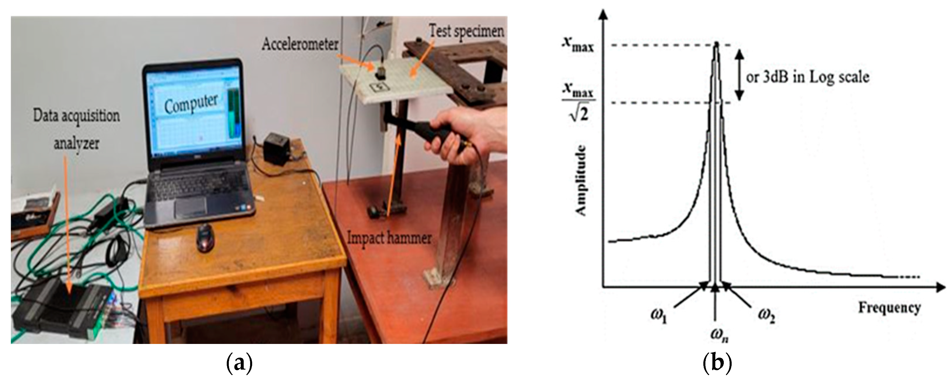
The dynamic parameters of GFRC laminates were determined using a vibration test set-up with B&K data acquisition type (3160-A-042) analyzer, equipped with B&K pulse 17.1 software, as shown in Figure 2a. To conduct the vibration test, an impact hammer, type (8202) of sensitivity 500 mV/g with impact tip to control the amplitude of applied force and avoid the overloading phenomena, was used as the excitation element. The responses were measured by a piezoelectric accelerometer type (4506) of a weight of 18 grams mounted on the specimens. FRF was automatically calculated and graphically presented on a PC display equipped with a multi-channel signal analyzer. Natural frequency was determined from FRF for each specimen and the half-power bandwidth method was used to calculate damping factor, as shown in Figure 2b, according to Equation (1).
ζ = ω 2 ω 1 2   ω n ,

3. Results and Discussion

3.1. Numerical Analysis Results from SOLIDWORKS

The fundamental natural frequency and its related mode shape were obtained for the specimens. The values of natural frequencies are listed in Table 3. It was noticed that the stacking sequence combination of [0]10 has the highest natural frequency. However, the combination of [90/±45/±35/90/0]s has the lowest natural frequency.

3.2. Experimental Modal Analysis Results

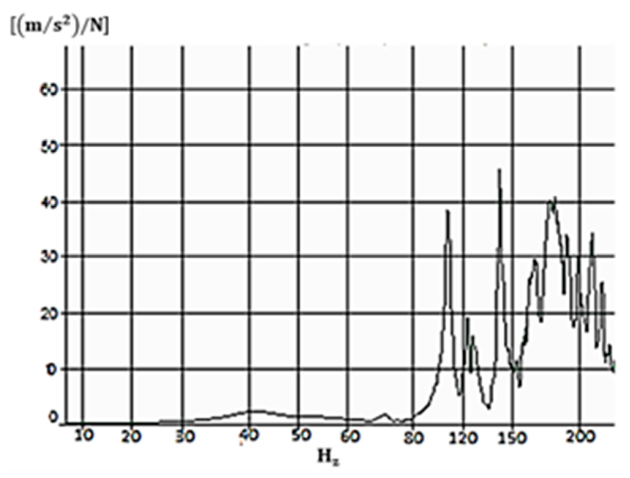
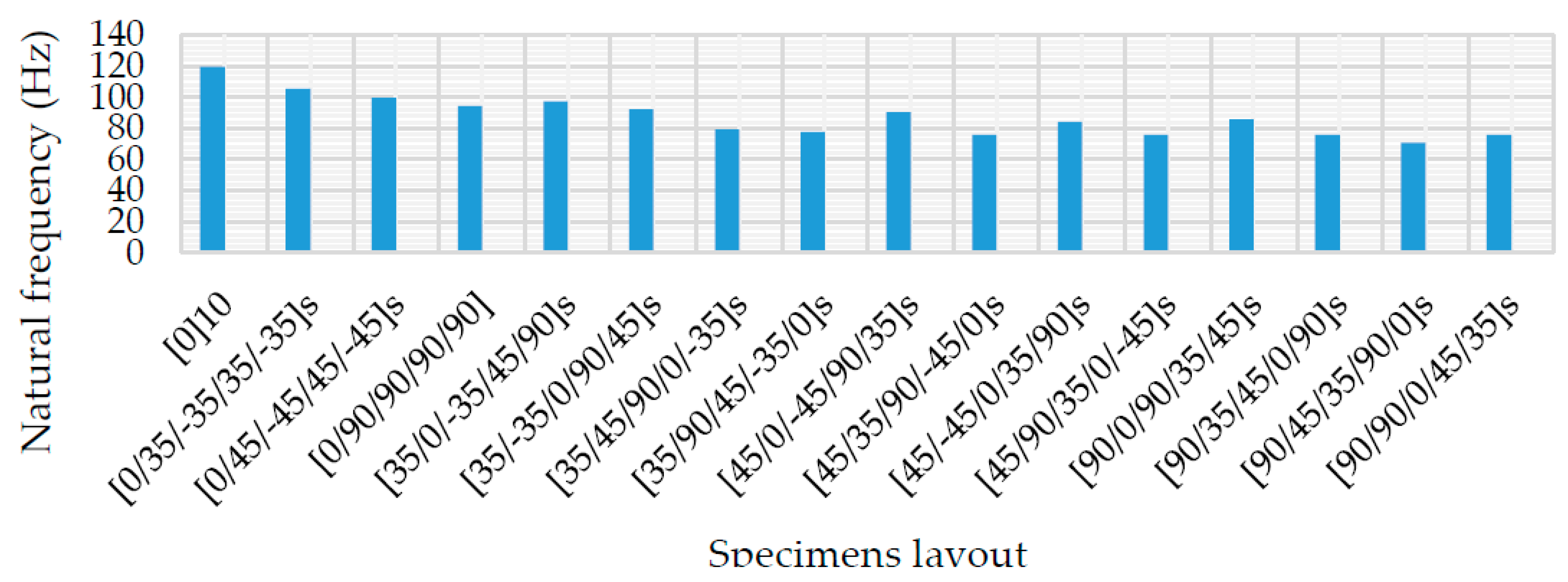
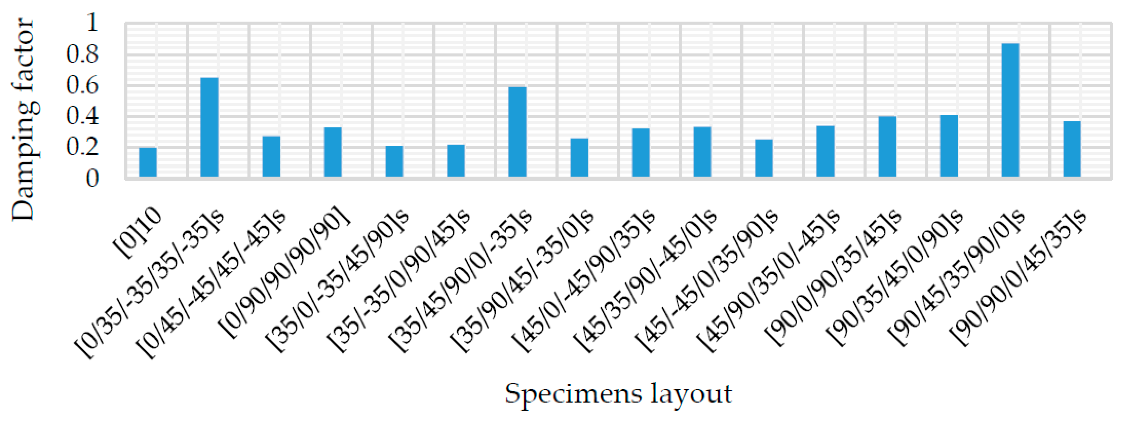
Experimental modal testing for the 16 test configurations was carried out and FRFs were obtained to determine the modal frequencies and damping factors. Figure 3 shows the frequency domain plot for [0]10 stacking sequence. The peak in the frequency domain plot state the modal frequency. The values of modal frequencies and the damping factors of all the specimens are shown in Table 3 and their plots are in Figure 4 and Figure 5.
It was noticed that the values of natural frequencies decrease as the angle of the outer layer increases. The fiber length in the longitudinal direction of the plate is reduced when the angle of the fiber increases; this reduces the reinforcement of glass fiber in the longitudinal direction and reduces the stiffness of the plate. The decrease in stiffness caused a decrease in natural frequency. However, the values of damping factors increase as the angle of the outer layer increases.

3.3. Comparison of Results

The numerical and experimental results are presented in Table 3; we can notice that there is good matching between the results. The deviation between the numerical and experimental results of natural frequencies came from the assumption of the SOLIDWORKS software, which deals with frequency analysis as undamped vibration analysis, therefore, the damping factors are representing the amount of this deviation.

3.4. Optimum Configurations Results

From the results obtained in Table 3 and implementing the Taguchi technique, which is used for identifying the optimal design parameters for maximum damping and minimum frequency, Table 4 shows the results of the analysis of variance (ANOVA) for frequency and damping factor. It is noticed that the angle of the outer layer plays the significant role in obtaining minimum frequency. However, the third layer angle is the most effective factor to obtain maximum damping. From Table 4, we can obtain the optimum stacking sequence for a minimum frequency of [90/90/90/0/0]s and optimum configuration for maximum damping of [90/±45/±35/90/±35]s.
A verification test was carried out for the optimum configurations of [90/90/90/0/0]s and [90/±45/±35/90/±35]s, the results were presented in Table 5, and the mode shapes of the tested model for the minimum frequency configuration were represented in Figure 6. The predicted error was calculated as follows:
Predicted error % = [(Test result − Predicted result)/Test result] × 100
It was noticed that there was a good agreement between the predicted and simulated results. The error between the test results and the predicted values for frequency was 3.8% and 4% for damping factor. Response surface modeling was used to establish the mathematical model between the frequency and damping factor and the various input design parameters as follows:
Frequency (Hz) = 237.2 − 19.9 A + 5.64 B + 11.87 C − 17.89 D − 13.83 E +
1.528 A2 + 0.956 B2 + 0.44 C2 + 1.299 D2 + 1.101 E2 − 0.909 AB − 0.634 AC +
0.133 AD − 2.64 BC
Damping = 29.6 − 11.2 A +1.5 B − 1.6 C − 4.4 D + 4.16 E + 0.279 A2 − 0.316 B2
0.171 C2 − 0.024 D2 − 0.257 E2 + 0.167 AB + 0.379 AC + 0.807 AD + 0.36 BC
where A, B, C, D, and E represent the input design parameters as first, second, third, fourth, and fifth ply orientations, respectively.

4. Conclusions

This study represents the significant role of composite materials in the isolation and control of vibration levels. The dynamic response of GFRCs was investigated numerically and experimentally. The optimum layouts for minimum frequency and maximum damping factor were deduced, respectively, using the Taguchi technique. The following concluding remarks have been obtained from this study:
  • The stacking sequence combination of [0]10 has the highest natural frequency and minimum damping ratio. However, the combination of [90/±45/±35/90/0]s has the lowest natural frequency and maximum damping ratio.
  • The dynamic characteristics, such as natural frequency and damping capacity of the composite isolator, are sensitive to the outer lamina orientation, the frequency decreases while the damping increases by increasing the outer laminas angles from 0° to 90°.
  • The optimum layouts for minimum frequency and maximum damping factor were identified using the Taguchi technique as follows [90/90/90/0/0]s and [90/±45/±35/90/±35]s, respectively.
  • The experimental testing verified the numerical results, which prove that the suggested finite element model of the composite plate provides an efficient tool for the dynamic analysis of the composite structure.
  • The verification test conducted at the optimum combination had shown a great agreement between the Taguchi method and FEM results, with a prediction error of 3.8% and 4% for frequency and damping, respectively.
  • The Taguchi technique is a very efficient and practical tool for modeling and optimizing laminated composite plates to achieve the desired vibration control levels.

Author Contributions

All authors participated in this manuscript equally in all its parts. All authors have read and agreed to the published version of the manuscript.

Funding

This research received no external funding.

Institutional Review Board Statement

Not applicable.

Informed Consent Statement

Not applicable.

Data Availability Statement

Not applicable.

Conflicts of Interest

The authors declare no conflict of interest.

References

  1. Verma, A.; Singh, V. Mechanical, Microstructural and Thermal Characterization of Epoxy-Based Human Hair-Reinforced Composites. J. Test. Eval. 2019, 47, 1193–1215. [Google Scholar] [CrossRef]
  2. Jain, N.; Singh, V.K.; Chauhan, S. Review on effect of chemical, thermal, additive treatment on mechanical properties of basalt fiber and their composites. J. Mech. Behav. Mater. 2017, 26, 205–211. [Google Scholar] [CrossRef]
  3. Verma, A.; Negi, P.; Singh, V.K. Experimental Analysis on Carbon Residuum Transformed Epoxy Resin: Chicken Feather Fiber Hybrid Composite. Polym. Compos. 2018, 40, 2690–2699. [Google Scholar] [CrossRef]
  4. Verma, A.; Negi, B.; Singh, V. Physical and Thermal Characterization of Chicken Feather Fiber and Crumb Rubber Reformed Epoxy Resin Hybrid Composite. Adv. Civ. Eng. Mater. 2018, 7, 538–557. [Google Scholar] [CrossRef]
  5. Verma, A.; Negi, P.; Singh, V.K. Experimental investigation of chicken feather fiber and crumb rubber reformed epoxy resin hybrid composite: Mechanical and microstructural characterization. J. Mech. Behav. Mater. 2018, 27, 1–24. [Google Scholar] [CrossRef]
  6. Verma, A.; Joshi, K.; Gour, A.; Singh, V. Mechanical Properties and Microstructure of Starch and Sisal Fiber Bio Composite Modified with Epoxy Resin. Mater. Perform. Charact. 2017, 6, 500–520. [Google Scholar]
  7. Verma, A.; Singh, C.; Singh, V.; Jain, N. Fabrication and Characterization of Chitosan coated Sisal Fiber—Phytagel modified Soy Protein based Green Composite. J. Compos. Mater. 2019, 53, 2481–2504. [Google Scholar] [CrossRef]
  8. Pandit, M.; Mukhopadhayay, S.H.M. Free Vibration Analysis of Laminated Composite Rectangular Plate Using Finite Element Method. J. Reinf. Plast. Compos. 2007, 26, 69–80. [Google Scholar] [CrossRef]
  9. Kumar, K.S.; Siva, I.; Jeyaraj, P.; Jappes, J.W.; Amico, S.C.; Rajini, N. Synergy of fiber length and content on free vibration and damping behavior of natural fiber reinforced polyester composite beams. Mater. Des. 2014, 56, 379–386. [Google Scholar]
  10. Sahoo, S.; Panda, S.; Singh, V. Experimental and numerical investigation of static and free vibration responses of woven glass/epoxy laminated composite plate. J. Mater.: Des. App. 2017, 231, 1–16. [Google Scholar] [CrossRef]
  11. Erkling, A.; Bulut, M.; Yeter, E. The Natural Frequency and Damping Properties of Glass/Carbon/Kevlar fibers. Sci. Eng. Compos. Mater. 2014, 22, 565–571. [Google Scholar]
  12. Lavate, R.S.; Patil, A.T.; Patil, A.M.; Hargude, N.V. Dynamic Response Analysis of Fiber Reinforced Composite Beam. J. Mech. Civ. Eng. 2013, 6, 38–47. [Google Scholar]
  13. Alexander, J.; Kumar, H.; Augustine, B. Frequency Response of Composite Laminates at Various Boundary Conditions. In Proceedings of the National Conference on “Advances In Modelling And Analysis Of Aerodynamic Systems (AMAAS-2013)”, Rourkela, India, 1–2 March 2013; pp. 11–15. [Google Scholar]
  14. Lee, S.K.; Kim, M.W.; Park, C.J.; Chol, M.J.; Kim, G.; Cho, J.-M.; Choi, C.-H. Effect of fiber orientation on acoustic and vibration response of a carbon fiber/epoxy composite plate: Natural vibration mode and sound radiation. Int. J. Mech. Sci. 2016, 117, 162–173. [Google Scholar] [CrossRef]
  15. Samal, P.K.; Pruthvi, I.; Suresh, B. Effect of fiber orientation on vibration response of glass epoxy composite beam. Mater. Today Proc. 2020, 43, 1519–1525. [Google Scholar] [CrossRef]
  16. Daoud, H.; Rebière, J.-L.; Makni, A.; Taktak, M.; El Mahi, A.; Haddar, M. Numerical and Experimental Characterization of the Dynamic Properties of Flax Fiber Reinforced Composites. Int. J. Appl. Mech. 2016, 8, 1650068. [Google Scholar] [CrossRef]
  17. Mahmoudi, S.; Kervoelen, A.; Robin, G.; Duigou, L.; Daya, E.; Cadou, J. Experimental and numerical investigation of the damping of flax–epoxy composite plates. Compos. Struct. 2018, 208, 426–433. [Google Scholar] [CrossRef]
  18. Rueppel, M.; Rion, J.; Dransfeld, C.; Fischer, C.; Masania, K. Damping of carbon fiber and flax fiber angle-ply composite laminates. Compos. Sci. Technol. 2017, 146, 1–9. [Google Scholar] [CrossRef]
  19. Zhang, J.; Yang, H.; Chen, C.; Zhang, Z. Structure and modal analysis of carbon fiber reinforced polymer raft frame. J. Low Freq. Noise Vib. Act. Control 2018, 37, 577–589. [Google Scholar]
  20. Khodadadi, A.; Liaghat, G.; Shahgholian-Ghahfarokhi, D.; Chizari, M.; Wang, B. Numerical and experimental investigation of impact on bilayer aluminum-rubber composite plate. Thin-Walled Struct. 2020, 149, 106673. [Google Scholar] [CrossRef]
  21. Taherzadeh-Fard, A.; Liaghat, G.; Ahmadi, H.; Razmkhah, O.; Charandabi, S.C.; Zarezadeh-Mehrizi, M.A.; Khodadadi, A. Experimental and numerical investigation of the impact response of elastomer layered fiber metal laminates (EFMLs). Compos. Struct. 2020, 245, 112264. [Google Scholar] [CrossRef]
  22. Khodadadi, A.; Liaghat, G.; Bahramian, A.R.; Ahmadi, H.; Anani, Y.; Asemani, S.; Razmkhah, O. High velocity impact behavior of Kevlar/rubber and Kevlar/epoxy composites: A comparative study. Compos. Struct. 2019, 216, 159–167. [Google Scholar] [CrossRef]
  23. Khodadadi, A.; Liaghat, G.; Ahmadi, H.; Bahramian, A.R.; Razmkhah, O. Impact response of Kevlar/rubber composite. Compos. Sci. Technol. 2019, 184, 107880. [Google Scholar] [CrossRef]
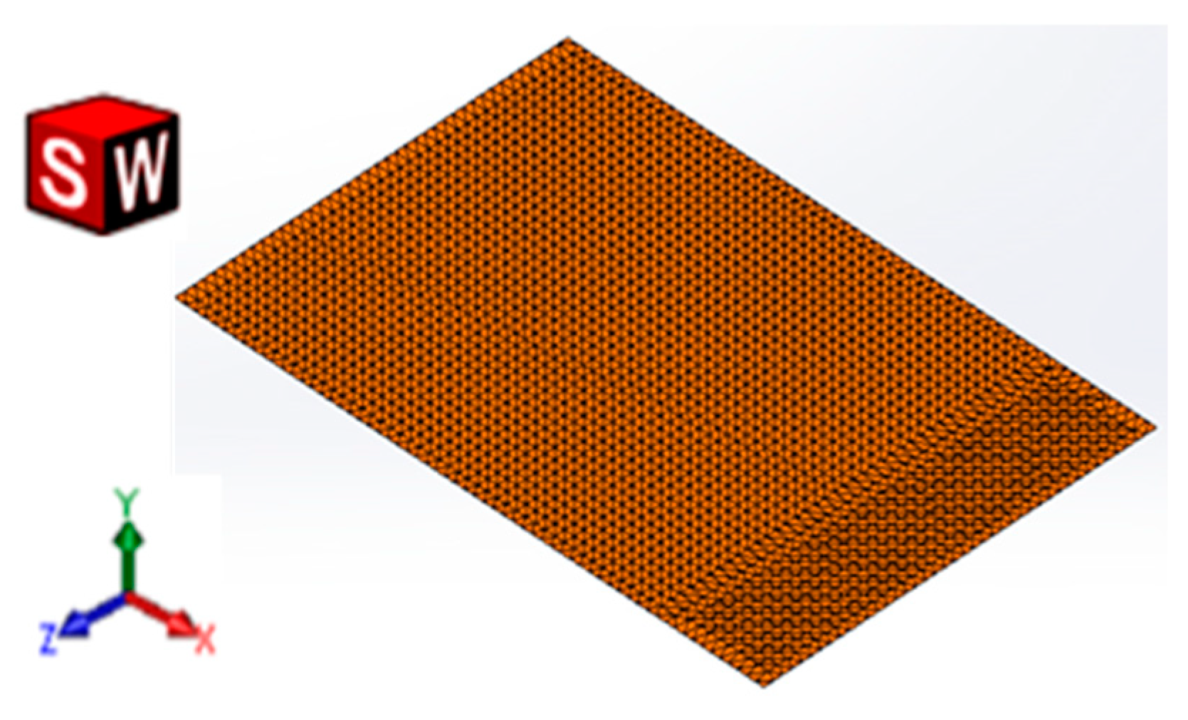
Figure 1. A 3D meshing model of a composite plate.
Psf 04 00031 g001
Figure 2. (a) Overall view of vibration test set-up, (b) Half power bandwidth method.
Psf 04 00031 g002
Figure 3. Frequency response function for [0]10 specimen.
Psf 04 00031 g003
Figure 4. Variation of natural frequencies with stacking sequences and fiber orientations.
Psf 04 00031 g004
Figure 5. Variation of damping factors with stacking sequences and fiber orientations.
Psf 04 00031 g005
Figure 6. Mode shapes of the optimum frequency configuration: (a) first mode, (b) second mode, and (c) third mode.
Psf 04 00031 g006
Table 1. Various configurations used for this study.
Run No.Input Parameters
1st Ply (A)2nd Ply (B)3rd Ply (C)4th Ply (D)5th Ply (E)
CodedActualCodedActualCodedActualCodedActualCodedActual
111111
212±35°2±35°2±35°2±35°
313±45°3±45°3±45°3±45°
41490°490°490°490°
52±35°12±35°3±45°490°
62±35°2±35°1490°3±45°
72±35°3±45°490°12±35°
82±35°490°3±45°2±35°1
93±45°13±45°490°2±35°
103±45°2±35°490°3±45°1
113±45°3±45°12±35°490°
123±45°490°2±35°13±45°
13490°1490°2±35°3±45°
14490°2±35°3±45°1490°
15490°3±45°2±35°490°1
16490°490°13±45°2±35°
Table 2. Orthotropic material properties for glass/polyester.
E11 (Pa)E22 (Pa)E33 (Pa)G12 (Pa)G13 (Pa)G23 (Pa)V12V13V23ρ (g/m3)
4.46 × 10101.21 × 10101.21 × 10104.1 × 1094.1 × 1094.18 × 1090.2640.2640.4452.03 × 106
Table 3. Comparison between numerical and experimental results.
Run No.Specimen LayoutNumerical Natural Frequency
(Hz)
Experimental Natural Frequency
(Hz)
Damping Factor
ζ
1[0]10121.43119.560.2
2[0/±35/±35/±35/±35]s106.3105.50.65
3[0/±45/±45/±45/±45]s101.0399.70.274
4[0/90/90/90/90]s96.32894.230.33
5[±35/0/±35/±45/90]s98.45797.640.21
6[±35/±35/0/90/±45]s93.81192.330.22
7[±35/±45/90/0/±35]s80.50579.320.59
8[±35/90/±45/±35/0]s78.72577.690.26
9[±45/0/±45/90/±35]s91.4790.640.325
10[±45/±35/90/±45/0]s76.22875.820.332
11[±45/±45/0/±35/90]s85.1484.170.254
12[±45/90/±35/0/±45]s76.32275.910.34
13[90/0/90/±35/±45]s86.41485.840.4
14[90/±35/±45/0/90]s76.581760.41
15[90/±45/±35/90/0]s71.35270.940.87
16[90/90/0/±45/±35]s76.23375.960.37
Table 4. Analysis of variance of frequency and damping results.
FactorFrequency ResultsDamping Results
Average η by Factor Level (dB)Average η by Factor Level (dB)
1234Rank1234Rank
A−40.5−38.84−38.28−37.78 *110.6629.2529.84713.6132 *2
B−39.88−38.83−38.47−38.22 *28.98911.44612.773 *10.1664
C−39.37−38.78−38.73−38.54 *38.38613.031 *9.89512.0631
D−38.78 *−38.95−38.81−38.85511.38411.1749.25411.562 *5
E−38.58 *−38.88−38.98−38.96411.18713.319 *9.5769.2923
* Optimum level.
Table 5. Comparison between the verification test result and additive model prediction.
Optimum ConditionCombination of Input ParametersVerification Test ResultModel PredictionPrediction Error (%)
Min Freq.A4B4C4D1E1[90/90/90/0/0]s68.57865.9783.8
Max DampingA4B3C2D4E2[90/±45/±35/90/±35]s0.970.934
Publisher’s Note: MDPI stays neutral with regard to jurisdictional claims in published maps and institutional affiliations.