Abstract
This article investigates the construction of a wind power generator requiring the lowest possible cost. The proposed model is an Axial Flux Permanent Magnet (AFPM) Synchronous Machine, which contains two iron rotors and a coreless stator between them, constructed from resin. The scientific contribution relates to the coupling of economic and technical parameters, which will clarify the feasibility, i.e., a wind turbine construction capable of producing approximately 3.5 KW, using a simple mill and a generator of nominal rotor speed 100 rpm. Such studies are few in international literature and mainly concern low levels of rotor speed in relation to the produced output power. For the generator dimensioning, analytical equations are used, while the type and the dimensions of the magnets are determined, before the start of dimensioning. The authors carried out research in the international market, ending up with specific cost-effective magnets, while trying to adjust the remaining dimensions and materials of the machine based on these cost-effective magnets and the aforementioned nominal values of the generator. The machine, whose dimensions are derived by analytical equations, was simulated and analyzed using the Two-Dimensional Finite Element Method (2D-FEM) and the Three-Dimensional Finite Element Method (3D-FEM), for comparison purposes. Moreover, an economic analysis of the generator and its individual parts was conducted. Finally, a novel idea for reducing the total generator cost is proposed, by replacing the rotor disks with rings. The investigation revealed that analytical equations can predict with satisfactory accuracy the generator’s parameters. In addition, as permanent magnets are the most expensive materials in the construction, their predetermination using low-cost magnets can reduce the construction cost. Finally, the proposed concept of a ring-shaped rotor instead of a disk rotor, provides a cost reduction of up to 20%.
1. Introduction
Designing an electromechanical system is a challenging procedure because of several factors that should be taken into account. Two of the most important aspects that should be considered while designing a reliable and effective construction, are the initial system cost and the repair cost. Both factors are crucial, as designers should construct the system with the most cost-effective but durable materials, at the minimum quantity required to ensure high power production. Particularly, the wind generator industry imposes use of materials with great reliability and long lifetime since any fault can create serious problems in the system. In addition, wind turbines are usually placed in isolated, often inaccessible areas, while some faults require the disconnection of the generator, thus reducing the energy production.
In the literature, many studies have investigated both design optimization [1,2,3,4,5,6,7,8,9,10,11,12,13,14] and fault identification [15,16,17,18,19,20,21,22,23,24] of wind generators. However, a small proportion of these studies investigated the financial impact on the generator construction. Moreover, the majority of studies concern the design of machines with nominal speed much higher than 100 rpm. In [1] a wind generator of 1 kW and 100 rpm, is optimized utilizing a Genetic Algorithm (GA), in order to produce the lowest cogging torque and the highest efficiency. The machine topology contains a double-sided rotor, a single stator and has nominal output power of 1 kW, which is contrary to the generator investigated in this article, that has to provide approximately 3.5 kW in output. Likewise, in [9], general sizing equations and the GA are used for optimization of a wind generator with nominal power of 1 kW and nominal speed of 100 rpm. In [12,25,26,27,28,29,30,31,32,33,34,35,36], design optimization of [8,37,38,39,40,41], Axial Flux Permanent Magnet Synchronous Machines (AFPMSM) with nominal speeds much higher than 100 rpm are proposed, while the economic effect of the optimization was not examined. In [8,37,38,39,40,41], AFPMSMs are optimized using the cost factor as a parameter. More specifically, in [8], the material of the permanent magnet was examined for machine optimization purposes by means of a Particle Swarm Optimization (PSO). The economic impact on the design process is also taken into account. In [37], the differential evolution algorithm is presented for designing a single-sided AFPM machine, of nominal speed 2800 rpm, with the maximum efficiency and the minimum cost. Five independent variables were taken into account in the optimization process, while the cost of the machine materials is considered in the investigation. However, the study does not mention the total cost of the system and the individual components. In [38], a double-sided stator single-rotor topology motor, with nominal speed 3800 rpm, for automotive applications was optimized using sizing equations. The influence on the machine construction cost was also examined. In [39], a New Hybrid DOE-DE Numerical Algorithm is proposed for machine optimization, while the material cost was also taken into account, although, the economic analysis presented the cost values normalized per unit, without providing the exact system prices. In [40], a fully superconducting wind generator was designed. The solution reduces the cost of the tower and the foundation, but it is impractical because a large number of cryocoolers are needed. In [41], a AFPM YASA double rotor generator of nominal speed 60 rpm, suitable for wind power systems, is proposed. The generator was optimized by selecting the suitable Halbach magnets array, while financial analysis was also conducted aiming for an integral market survey concept. In [42], a novel axial-radial flux PM machine is proposed with very good performance but higher cost compared to a radial rotor machine. Likewise, in [43], a machine of the same structure was analyzed, which can be used for low cost home appliance applications.
In this article, an investigation was conducted in order to construct a 3–3.5 kW wind generator, with nominal speed of 100 rpm. The generator consists of two iron rotors and one stator between them, made of resin. The goal was to build a low-speed, gearless, cost-effective, simple and environmentally friendly generator, which could be installed in a residential area, even in a home garden, and would work without risk. It is unusual to develop a low-power generator with low-rotational speed and this study examined the feasibility of this concept. As previously mentioned, most of the studies in the international literature, have investigated generators with higher rotor speeds. Therefore, the authors investigated whether it is feasible from the technological and economic points of view to build such a machine capable of producing 3.5 kW at such low rotor revolutions. One of the most important optimization parameters in the procedure was the decrement in the quantity of permanent magnets that were used. However, permanent magnets with higher dimensions and higher grade contribute to a wind generator with higher output power. Consequently, the authors tried to find alternative ways to retain the output power roughly constant at 3.5 kW, exploring the possibility of increasing the generator winding coil dimensions and consequently the generator diameter. In Section 2, the authors design the machine model using analytical equations and predetermine the shape, material and dimensions of the permanent magnets of the generator. This task is performed first in order to minimize the magnets cost, while adjusting the rest of the design parameters accordingly to achieve the desired output power at the nominal speed of 100 rpm. Then, the machine is simulated using both 2D-FEM and 3D-FEM, for comparison purposes. In Section 3, the results from 2D and 3D FEM analysis are presented and compared. In addition, an economic analysis of the machine total cost and its individual parts is performed. Subsequently, in Section 4, a new idea for reducing the construction cost even more is proposed. This novel idea is based on replacing the machine rotor disks with rings, reducing the total generator cost and the iron losses of the generator. Finally, in Section 5, the main results and conclusions derived from the investigation are discussed, while in Section 6 future extensions of this study are proposed.
2. Materials and Methods
2.1. Designing the Generator Using Analytical Equations [44,45,46]
The first step before simulating every system in FEM is to compute its basic parameters using analytical equations. The use of analytical equations demands less time compared to FEM and can provide a reference point for starting the design. Considering that the desired wind generator should have an output power approximately 3.5 kW, nominal frequency 50 Hz and nominal speed 100 rpm, the number of pole pairs can be exported utilizing the fundamental equation related to synchronous machines [47]:
where ns is the generator nominal speed, is the generator fundamental frequency, and p are the machine pole pairs. Afterwards, the number of winding coils can be computed using Equation (2):
where Q is the total number of machine coils. According to [44], Equation (2) can be successfully applied when the number of generator poles is divided by four and the winding is single-layer. Consequently, using the above equations, the generator contains 60 magnets in each rotor, while its winding consists of 45 coils.
The outer and inner generator radius can be calculated by Equations (3) and (4):
where Td is the torque given by Equation (5):
ksc is the stator coefficient, kec is the winding edge coefficient, and kr the radius coefficient, calculated by (6), (7), and (8), respectively:
Jmax is the maximum current density, tw is the stator thickness, kf is the coil fill factor equal to 0.55, q is the number of coils per phase, the quantity sr is determined as equal to 0.9, and Bp is the amplitude of the first harmonic of the magnetic flux density in the airgap given by (9):
Bmg is the maximum value of the magnetic flux density in the airgap, equal to 0.528 T for a magnet of grade 35 N, while Λ can be calculated using (10):
and kp is the winding pitch factor calculated using Equation (11):
where k is calculated by (12):
z is a safety constant, P is the output power of the generator, η is the generator efficiency, while kd is the winding width distribution coefficient, which equals 1 for a single layer winding.
Finally, the quantity δc can be computed using (13):
Respectively, the number of turns in each coil can be calculated by Equation (14):
where Vphase is the rms value of the phase Electromotive Force (EMF) voltage during start-up, ravg is the average radius of the machine, la is the difference between generator outer and inner radius, la = ro − ri, k1 equals 0.2, while we is calculated by Equation (15), utilizing the cut-in wind speed as follows:
Regarding the coil leg width, it can be calculated using (16):
For the computation of the ohmic resistance of each phase, Equation (17) can be utilized as follows:
where ρt can be given by Equation (18):
tc is the maximum temperature value in which the generator can operate, and the average length of the coil turn lavg is computed by Equation (19):
The type of the magnets was predetermined and will have an influence on the remaining dimensioning procedure. As mentioned above, since the permanent magnets are the most expensive materials of the generator, the authors made a more inexpensive selection of magnets with a length of 50 mm, a width of 20 mm, and a thickness of 10 mm. The magnets are of rectangular shape, made by NdFeB and their grade is 35 N. Table 1 summarizes the most basic rotor parameters.

Table 1.
Basic rotor parameters.
Consequently, considering that the magnet length was 50 mm, the authors decided to fix the coil leg height, la, to 54 mm. Also, the stator thickness tw was set at 20 mm, in order that the distance between the magnets be greater than twice their thickness. In addition, using Equations (3) and (4), ro and ri can be calculated as being equal to 537 mm and 483 mm, respectively, as summarized in Table 2. Moreover, using (16), wc can be computed to be equal to 26.5 mm, while the number of turns per coil, Nc, is calculated using (14) and has a value of 145. Table 3 describes the basic stator parameters.
Table 2.
Generator radius.
Table 3.
Basic stator parameters.
2.2. Designing the Generator Using OpenAFPM 2D-FEM
The OpenAFPM modeling tool is a design software for Axial Flux Permanent Magnet Generators for wind electric systems https://www.openafpm.net/, which uses 2D-FEM. More specifically, the selected tool was UserAFPM. This tool was used to validate the performance of a specific generator geometry, by performing a Finite Element Analysis (FEA).
In order for the software to export the results, some basic parameters should be included. The generator input parameters used in the OpenAFPM 2D-FEM program are the same as those used for 3D-FEM simulation using Opera 18R2 software, and consequently the same as those calculated using the analytical equations.
Table 4 summarizes the blade rotor inputs used for the simulation. In addition, the copper resistivity is set to 1.678 × 10⁻⁸ Ω·m, the copper density is set to 8.94 g/cm3, the iron density is taken as being equal to 7.87 g/cm3, and the resin density is taken as equal to 1.36 g/cm3. Regarding the financial parameters the cost of each machine material and the labor cost, according to the current prices in the Hellenic/Greek market in September 2023, are summarized in Table 5.
Table 4.
Blade rotor inputs.
Table 5.
Cost of machine materials and labor cost.
In addition, both the transmission cable losses are considered to amount to 10%, while the resulting stator nominal temperature is equal to 57.7 °C.
2.3. Designing the Generator Using 3D-FEM
In this section, the generator, based on dimensions provided by the above analytical calculations, is modeled using 3D-FEM in Opera 18R2 software. The 3D-FEM is an accurate simulation tool, especially for constructions such as the AFPM synchronous machine, which has an inherent three-dimensional geometry. More specifically, in this machine type, the magnetic flux density is dependent on the radius, and this phenomenon is enhanced by the fact that the generator has a great rotor diameter compared to its axial length [49]. As mentioned earlier, the machine consists of two rotors and one coreless stator between them, constructed of resin. The stator winding is star-connected, non-overlapping, single-layer, of trapezoidal shape, consisting of 45 coils, and as depicted in Figure 1.
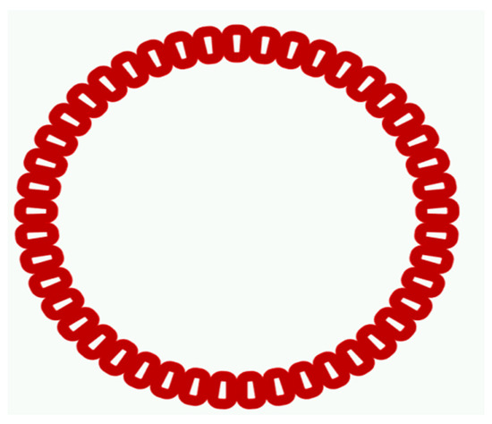
Figure 1.
The stator winding in 3D-FEM software.
Respectively, Figure 2 depicts the permanent magnets of the two rotors and their relative position with the generator stator winding. Each rotor contains north- and south-pole magnets, while the magnets that are opposite to each other are of different polarity. The north magnets are depicted with blue color, while the south magnets are depicted with green color.
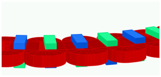
Figure 2.
The magnets and the stator winding in 3D-FEM software.
Figure 3 illustrates the meshed FEM model of the generator. The 3D model consists of 4,835,673 elements, while the transient analysis solver with motion was used for computational purposes. The light green color represents the two rotor iron disks of the generator. The stator disk does not appear in the figure, as the resin, of which it consists, was simulated with air properties.
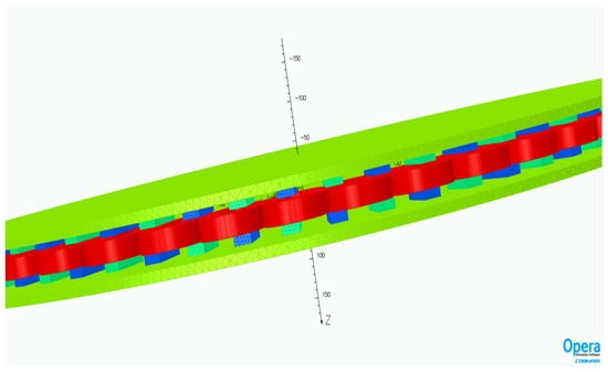
Figure 3.
The meshed FEM model of the generator.
2.4. The Mass Production versus Dispersed Construction Economics—Economic Evaluation and Feasibility of a Dispersed Produced Low Speed Small Generator
In this section, the generator, based on dimensions provided by the low nominal rotational speed results in the mass increase of any rotating power transformer of a given rated power. The required torque of such a machine results in higher load on the generator mechanical elements. So, both, the resulting raw material and labor cost increase, constituting a good reason to avoid such low speed machines. Our aim to examine an electric generator rated in the domain 3 kW to 6 kW and 160 rpm to 80 rpm should not be considered serious following the above reasoning, which is valid for the current electric generator concepts based on the current industrial production system as it has been developed until now all over the world. This current production conception is adaptable to the industrial machine tools, robotics, and relevant raw material and spare parts market, permitting high accuracy machining, fast production rate, optimal design conception, in this production frame, and feasible price within an international market.
The proposed generator concept in this paper is based on a non-massive production system providing a very low speed generator, impossible to survive among massively produced high-speed generators.
The main reason to examine such a non-trivial concept is the recognition, consideration, and attractiveness of a motive to produce goods providing social value and not only exchange value. If the generator additive value is recognized, accounted, and required as socially added value, a calmer production environment could be considered in the place of massive, concentrated production units. The low speed generator proposed here could be considered in harmonic combination with an appropriate motor, a low speed wind generator sail-mill concept defined on the same dispersed, but not massive, production methods. This low-speed electricity producing windmill needs a low-speed generator, not existing in the market, to integrate a small wind generator able to provide electricity with a high percentage of value addition within local communities who are able to produce their electricity production infrastructure. This electricity production mode can support the social coherence establishment and maintenance as a product between local community members’ education times their economy. Education and economy are, of course, interacting so their product, namely, the community social coherence, the so-called communion, is a nonlinear product, able to be examined under a law system correlating the law of nature, the technical norms and standards, and the society law. This law system is based on the relation of society law with the product of norms/standards times the nature law. Society law must be distinguished between the other laws and the state law especially. The society law governs the intensity of social relations, the motives synthesized with knowledge times mind and senses. The intensity provided by the social law is produced by the laws of technology, the norms and the standards times the laws of nature; it is a product of the human activity times the nature. The ethics and the social aesthetics should be combined with the technical standards and norms despite the fact that, historically, they are considered as completely irrelevant concepts during the recent five centuries after the Renaissance and the illumination in western Europe, first and then the rest of correlated countries today. If the results of the technical standards use and the norms application could be recognized and evaluated for their result on the society body, the relation between standards and ethics would be obvious.
In most social activity cases, the products of the following:
- the education/culture times economy,
- the nature law times norms/standards
- the use value times exchange value,
Namely, the communion, the society law, and the value (the social value) are not accounted at all. The main law used in practice economy law, governing our social life, is the so-called law of supply and demand. The relation among goods conception, goods development, and goods production is not in consideration in this well-oriented social, scientific and practice field of economics. The examination of the global (social) value relation with the product of the law times the communion (society intensity) as they are presented above, is applied in the case of this special low speed generator given both the technical norms governing its concept and the laws of physics (nature is ‘physis’, φύσις in Greek). So, if the society intensity (the communion) is produced by the education/culture times the social economy, then mass production of goods that people do not have access to in their production chain, creates a mass of consuming goods out of social culture and under the control of ‘specialists’ structures’ strongly correlated and depending on the owners of the production infrastructure. Knowledge is well conserved and protected as intellectual property in the frames and the law of specialized cognition areas and levels and subjects of training. A step towards the production of an electrical generator, suitable to be constructed using widely dispersed machinery like laser cutters, small lathes, welding units, etc., can be considered under the possibility of the social coherence reinforcement. The key reason to do so is the development of the social coherence produced by the constructors’ culture times their economy improvement.
This product, the culture times the economy makes the difference between centralized mass production and dispersed integrated construction. The first provides high exchange value products, cost effective to increase consumption. The second provides both exchange and use valued products able to be developed and producing a social intensity value as a product of the construction culture times the local economy. This product does not exist in communities consuming the majority of goods without any participation in their production. A non-producing society, or a society specialized to produce few goods not related to them, has no coherence and future.
An accountable benefit of dispersed against massive production cannot yet be defined and calculated in the frame of ordinary/current techno-economic feasibility criteria. Integrated criteria on a holistic social evaluation procedure, produced from cultural evaluation criteria times technological criteria (accordance to normalized practices and production standards) are introduced to overcome the lack of accountable measures of the distance between mass production and dispersed construction. This is not the main subject of this paper but the general relation among common values, culture, and economy is simply written as:
Common value = culture × economy
In the above relation the symbol: × means a holistic production operation between entities described with more than one characteristic. For the sake of resemblance to mind behavior, the term noetic is introduced for such operations. So, we establish noetic addition, production, and exposure to a force. The noetic (or mind) operations can be detected in the neurons systems. So, the ‘noetic price’ of the communion value is a product of the cultural value ‘noetic price’ times the economic value ‘noetic price’. If the economic value price is measured by money, the cultural value should not be, because the culture is qualitatively different from the economy, so cultural values should be measured by different units rather than economic value measurement. It is obvious that if a measure of the culture appears, the measure of the social value will be equal to the product of the culture times the economy measures.
Based on the above described approach, the question, why a heavy machine, demanding laborious construction is preferred to a lower weight and automatically produced machine has the following answer: The communion value, deduced as a product of the cultural value times the economic value of the machine is more important than the exchange value produced by experts and specialized workers but is unable to communicate with other specialists and machines irrelevant to their cognition, knowledge, and experience fields.
Following that briefly discussed above holistic evaluation of the machine
- conception result
- production result
- operation result
The social value hypostases are suitable to evaluate society coherence.
This society coherence is internationally used to develop, evaluation methods of human activities. The common methods follow isolation of the exchange value, the money priced method based on the supply and demand law. It must be noted that this law is not valid on the machines conceptual design practices and also among human relations practices.
Consequently, how could one imagine our reality without all those everyday new surprising events and concepts? The demand of new concepts can never be satisfied by any supply because new concepts have never been in the market before their appearance. So, in order to apply the ‘supply-demand law’, one has to construct both supply and demand of a non-existing, and not yet priced, prototype within the community where it is of interest to address the new prototype. It must be noted that new things have no demand and zero supply. It must also be noed that new things are generated after social interaction of people and artifacts.
So, the reason why we are examining such a low speed heavy and laborious machine but suitable to be constructed everywhere, is the resulting social coherence developed and enforced by such production methods against the massive production of consumption goods.
3. Results
In this section, the results obtained from the simulation using both 2D and 3D FEM analysis are presented and compared. In addition, an economic analysis of the total cost of the generator and its parts is presented.
3.1. Simulation Results Using 3D-FEM
In this paragraph, the 3D-FEM simulation results are presented and discussed. Figure 4 depicts the generator output voltage when the generator has its nominal speed and load. Respectively, Figure 5 illustrates the generator current for the nominal speed of 100 rpm. As can be seen from these figures, at the nominal speed the machine has an rms EMF voltage of 219 V and rms current of 5.1 A. Consequently, the generator output power can be calculated to be approximately equal to 3350 W.
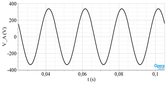
Figure 4.
The EMF voltage of phase A at nominal generator speed.
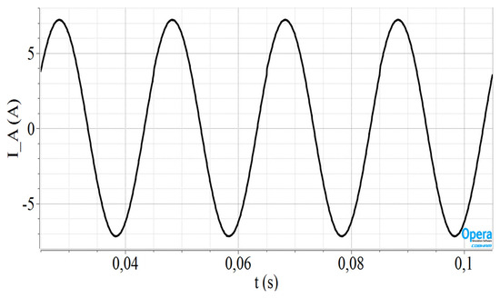
Figure 5.
The current of phase A at nominal generator speed.
3.2. Economic Cost Estimation Results Using OpenAFPM 2D-FEM
In this paragraph, the results derived by 2D-FEM simulation using OpenAFPM are presented and compared to those of the 3D-FEM simulation. The comparison is held for validation purposes, while an economic analysis of the generator, using OpenAFPM software, is also presented. As the simulation model was validated previously with 3D-FEM, for the financial analysis, the OpenAFPM tool is used, which enables quicker and simpler analysis. More specifically, the OpenAFPM software needs 15 min to provide results, while the 3-FEM using Opera 18R2 needs about 2 days.
The basic input parameters of the program have already been discussed in the previous sections and are kept the same as in the 3D-FEM simulation.
Figure 6 depicts the magnetic flux density in different machine regions, while Figure 7 shows the estimated generator efficiency versus the rotor speed. This is the expected efficiency, given that an optimization of the generator dimensions has not been achieved because of the low-cost permanent magnets. As the market is unpredictable, it makes no sense to make precise techno-economic calculations. The maximum efficiency is achieved for a rotor speed equal to 100 rpm, which is the nominal speed. In addition, efficiency is expected to decrease at very low or very high wind speeds. The definition of the generator efficiency can be given by (20):
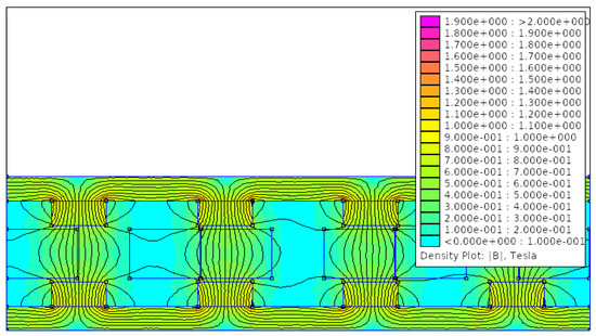
Figure 6.
The magnetic flux density of the generator derived by 2D-FEM.
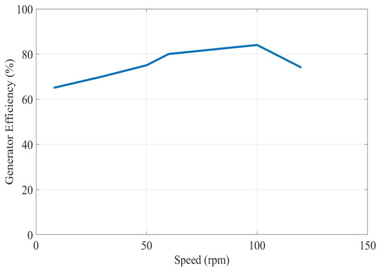
Figure 7.
The generator efficiency versus rotor speed.
Consequently, it is clear that the efficiency depends on the dimensions of the generator and the rotor speed.
Table 6 summarizes the stator output parameters. In the OpenAFPM software, the stator current at the nominal wind speed was preset by the authors as an input parameter equal to 5.1 A, in other words with the value that was provided by 3D-FEM Opera 18R2 software. Then, the software returns the rms value of the EMF voltage at the nominal wind speed. Observing Table 6, this value is equal to 224.525 V, which is close to the value of 219 V that the 3D-FEM simulation provides. The average length of coil-turn values calculated by OpenAFPM and Equation (19) are 202.16 mm and 209.51 mm, respectively, while the phase resistance is calculated at approximately 4.7 Ohm using the 2D-FEM analysis, and in the 3D-FEM software the value of 4.2 Ohm is used, calculated by Equation (17). The above values are adequately close to each other, and the small deviations result from the more accurate analysis performed in three dimensions due to the inherent three-dimensional geometry of the AFPM synchronous machine. Finally, the generator output value is 3435.23 W which is close to the value calculated by 3D-FEM.
Table 6.
Generator stator output parameters derived from OpenAFPM.
Table 7 presents the generator losses calculated by OpenAFPM, while Table 8 computes the masses of the different parts of the generator, the total generator mass, the mass of the bearing hub, and the blade rotor mass.
Table 7.
Generator losses calculated by OpenAFPM.
Table 8.
Masses of generator parts calculated by OpenAFPM.
Finally, Table 9 computes the total generator cost and the cost of its individual parts. The calculation is achieved using the material prices presented in Table 5 and the mass of each material calculated in Table 8.
Table 9.
Generator cost estimation.
From Table 9, it can be observed that the total generator cost amounts to EUR 1767.53.
4. Suggestion for Novel Generator Concept
In this section, the authors propose a new idea for generator design which reduces the total construction cost. In Figure 8, the meshed FEM model of this novel generator in front and side view, is depicted. The 3D model consists of 3,745,423 elements, while the transient analysis solver with motion was used for computational purposes. The stator disk, as previously conducted, does not appear in the figure as it is made of resin and has been determined in the software with the properties of air. The rotor disks are illustrated with a light green color, while each of them is made of a thin ring. This representation has been carried out because the real model of the machine, which will be constructed soon and be presented in a future article, will contain two rings for rotors. This solution is proposed in order to reduce the cost of the generator construction, using as simple and inexpensive materials as possible.
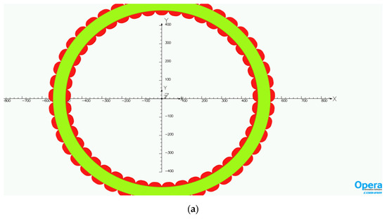
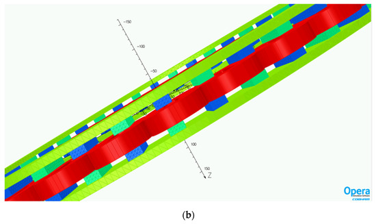
Figure 8.
The meshed FEM model of the novel generator: (a) front view, (b) side view.
Figure 9 and Figure 10 present the EMF voltage and the stator current of the machine with the novel design, when the rotor speed and the load are nominal. Looking at these figures it can observed that the replacement of the two rotor disks with two rings will not change the values of the generator exported voltage and current. Consequently, the generator output power will not be reduced. On the other hand, as less iron quantity is used, the iron losses of the machine will be reduced, together with the total generator cost.
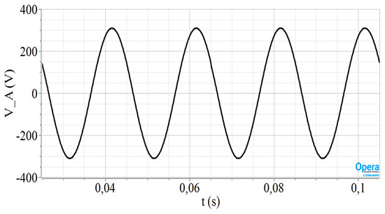
Figure 9.
Simulation results for the new generator construction: The EMF voltage of phase A at nominal generator speed.
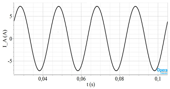
Figure 10.
Simulation results for the new generator construction: The current of phase A at nominal generator speed.
As shown in Table 9, the cost of iron amounts to EUR 242.41 €, for a generator with two rotor disks, while the total volume of the rotor disks is equal to 18,118.8 cm3. In this section, the new total volume of the rotor disks will be computed using Equation (21):
where D and d are the outer and inner diameters of the ring respectively, and h is the height of the ring. Consequently, the total volume of the two rotors is calculated to be equal to 3843.36 cm3 and by considering that the iron density is 7.874 g/cm3 the total mass of the rotor disks is 30.2626 kg. Then using the iron price given in Table 5, the estimated cost of the iron turns out to be equal to EUR 51.446. The cost estimate for the proposed novel generator model is presented in Table 10. It can be expected that the use of the two rings instead of the two rotor disks reduces the total cost by about EUR 200, which is significant if large-scale generator production is considered.
Table 10.
Cost estimation for the proposed novel generator model.
Finally, Table 11 presents the total labor cost in a few European countries. The generator needs about five working days to be constructed and we make the assumption that the raw material prices are roughly constant in these European countries.
Table 11.
Total labor cost estimation in different European countries [50].
5. Discussion
In this study, an AFPM Synchronous Generator, suitable for wind power applica-tions, of nominal speed 100 rpm and nominal output power approximately 3–3.5 kW was dimensioned and investigated. The dimensioning procedure was based on analytical equations, while the shape, the material, and the dimensions of the permanent magnets were preset, in order for the machine to be designed using, affordable magnets. Consequently, the authors tried to adjust the rest of the parameters of the generator to the desired output values to reduce the cost of the permanent magnets, which is the most expensive material of the machine.
Then the generator was simulated using both 2D-FEM and 3D-FEM, while the simulation results were discussed regarding their accuracy. The comparison showed that these results are quite close to each other, but some deviations exist as a three-dimensional analysis will provide more accurate results as it considers the inherent 3d geometry of this machine type. The rms values of the EMF voltage and the stator current, at the nominal wind speed and load, are calculated roughly as equal to 220 V and 5.1 A, respectively, resulting in an output generator power close to 3.5 kW.
In addition, an economic analysis of the generator was conducted using the OpenAFPM simulation software. The analysis reveals that the total cost of the generator, using the two rotor disks construction, is EUR 1767.53.
Subsequently, the authors proposed a new idea for constructing the two generator rotors using rings instead of disks. This modification will not affect the rms values of the generator voltage and current but will reduce the iron losses and the total construction cost by reducing the volume of the utilized iron. The estimated total construction cost of the proposed generator will be EUR 1576.569, approximately EUR 200 less than the initial estimated cost. This money-saving is vital, especially in large scale generator production, where the goal is to produce at high electric energy levels using simple and cost-effective materials.
Finally, the next step of this study includes the construction of the generator in the laboratory for further validation purposes as well as the installation of the machine in a real wind power system. As wind parks contain a great number of wind turbines, the authors tried to find a solution to reduce the total cost. The coupling of economic and technical parameters is a very important issue, which has not been studied sufficiently in the international literature, especially for low-speed generators. Therefore, the authors investigated, if it is financially beneficial to construct a simple and environmentally friendly generator, capable of producing 3.5 kW in 100 rpm nominal rotor speed. This machine could be powered by a mill and could be safely used, in residential areas, even in residences. The study proved that it is technically effective to construct a low-power generator with low-rotational speed, if rings instead of rotor disks are used, thus reducing the size and cost of the structure.
6. Hints for Further Results
Apart from building the generator in the laboratory, an issue for further consideration could be a feasibility study regarding the geography of the machine production. Every feasibility study shows whether a business idea is viable, the technical and financial obstacles arising from the idea, while serving the industry to produce at the lowest possible cost. As both raw materials and labor costs vary from country to country, the authors consider that the economic variations resulting from generator manufacture in different countries should be studied in more detail, using simple economic models. Already from the present study, which considers the cost of raw materials to be constant in the investigated countries, it can be seen that the production cost increases considerably if the same generator is manufactured in France instead of Bulgaria. Therefore, a more detailed coupling of technical and economic parameters from the point of view of the manufacturing country could be an interesting future study.
Author Contributions
All authors contributed to this paper: investigation, methodology, software, validation A.C.B., R.P. and D.C.; writing A.C.B. and D.C.; project administration C.C. and D.C.; review and editing D.C. All authors have read and agreed to the published version of the manuscript.
Funding
This research received no external funding.
Data Availability Statement
Data are contained within the article.
Acknowledgments
The authors would like to thank the Laboratory of Electromechanical Energy Conversion at the University of Patras, for providing access to its facilities, to conduct our simulations using the Opera 18R2 software. In addition, the author would like to acknowledge the contribution of Georgios Orfanoudakis for his fruitful advice in the improvement on the text from scientific and syntax points of view and Gareth Owens, HMU—International Relations Office, for his comments and improvements regarding the English language.
Conflicts of Interest
The authors declare no conflict of interest.
References
- Taran, N. Efficiency Optimi Ization of an Axial Flu Ux Permanent Magnet Synchrono Ous Generator for Low w Speed Wind. In Proceedings of the 2014 22nd Iranian Conference on Electrical Engineering, Tehran, Iran, 20–22 May 2014; IEEE: Piscataway, NJ, USA, 2014; pp. 539–544. [Google Scholar]
- Kappatou, J.C.; Zalokostas, G.D.; Spyratos, D.A. 3-D FEM Analysis, Prototyping and Tests of an Axial Flux Permanent-Magnet Wind Generator. Energies 2017, 10, 1269. [Google Scholar] [CrossRef]
- Lee, S.H.; Kim, Y.J.; Lee, K.S.; Kim, S.J. Multiobjective Optimization Design of Small-Scale Wind Power Generator with Outer Rotor Based on Box-Behnken Design. IEEE Trans. Appl. Supercond. 2016, 26, 5202605. [Google Scholar] [CrossRef]
- Saruwatari, M.; Yun, K.; Iwakuma, M.; Tamura, K.; Hase, Y.; Sasamori, Y.; Izumi, T. Design Study of 15-MW Fully Superconducting Generators for Offshore Wind Turbine. IEEE Trans. Appl. Supercond. 2016, 26, 5206805. [Google Scholar] [CrossRef]
- Nakamura, K.; Ichinokura, O. Super-Multipolar Permanent Magnet Reluctance Generator Designed for Small-Scale Wind-Turbine Generation. IEEE Trans. Magn. 2012, 48, 3311–3314. [Google Scholar] [CrossRef]
- Imanuddin, N.; Furqani, J.; Rizqiawan, A. Effects of Radial Divided Magnet Shifting on Cogging Torque of Axial Flux Permanent Magnet Generator for Small Scale Wind Turbine. In Proceedings of the 2023 4th International Conference on High Voltage Engineering and Power Systems (ICHVEPS), Sanur-Denpasar, Indonesia, 6–10 August 2023; pp. 555–560. [Google Scholar] [CrossRef]
- Kappatou, J.C.; Zalokostas, G.D.; Spyratos, D.A. Design Optimization of Axial Flux Permanent Magnet (AFPM) Synchronous Machine Using 3D FEM Analysis. J. Electromagn. Anal. Appl. 2016, 8, 247–260. [Google Scholar] [CrossRef]
- Latoufis, K.; Troullaki, K.; Pazios, T.; Hatziargyriou, N. Design of Axial Flux Permanent Magnet Generators Using Various Magnetic Materials in Locally Manufactured Small Wind Turbines. In Proceedings of the 2016 22nd International Conference on Electrical Machines, ICEM 2016, Lausanne, Switzerland, 4–7 September 2016; pp. 1545–1551. [Google Scholar] [CrossRef]
- Taran, N.; Ardebili, M. A Novel Approach for Efficiency and Power Density Optimization of an Axial Flux Permanent Magnet Generator through Genetic Algorithm and Finite Element Analysis. In Proceedings of the 2014 IEEE 23rd International Symposium on Industrial Electronics (ISIE), Istanbul, Turkey, 1–4 June 2014; pp. 709–714. [Google Scholar] [CrossRef]
- Zhao, X.; Niu, S.; Fu, W. Sensitivity Analysis and Design Optimization of a New Hybrid-Excited Dual-PM Generator with Relieving-DC-Saturation Structure for Stand-Alone Wind Power Generation. IEEE Trans. Magn. 2020, 56, 7504105. [Google Scholar] [CrossRef]
- Labuschagne, C.J.J.; Kamper, M.J. Design Optimisation and Comparison of Non-Overlap Winding PM Wind Generators for Active and Passive Battery Charging Systems. In Proceedings of the 23rd International Conference on Electrical Machines, ICEM Alexandroupoli, Greece, 3–6 September 2018; pp. 690–696. [Google Scholar] [CrossRef]
- Beik, O.; Al-Adsani, A.S. A Wind Turbine Generator Design and Optimization for DC Collector Grids. IEEE J. Emerg. Sel. Top. Power Electron. 2022, 10, 484–493. [Google Scholar] [CrossRef]
- Bhuiyan, N.A.; McDonald, A. Optimization and Comparison of Flux-Concentrating Nd-Fe-B Generator Considering Variable Power Factor and Wind Conditions for a 6MW Offshore Wind Turbine. In Proceedings of the 53rd International Universities Power Engineering Conference, UPEC 2018, Glasgow, UK, 4–7 September 2018; pp. 1–5. [Google Scholar] [CrossRef]
- Karmaker, H.; Ho, M.; Kulkarni, D. Comparison between Different Design Topologies for Multi-Megawatt Direct Drive Wind Generators Using Improved Second Generation High Temperature Superconductors. IEEE Trans. Appl. Supercond. 2015, 25, 5201605. [Google Scholar] [CrossRef]
- Barmpatza, A.C.; Kappatou, J.C. Study of the Total Demagnetization Fault of an AFPM Wind Generator. IEEE Trans. Energy Convers. 2021, 36, 725–736. [Google Scholar] [CrossRef]
- Minaz, M.R.; Akcan, E. An Effective Method for Detection of Demagnetization Fault in Axial Flux Coreless PMSG with Texture-Based Analysis. IEEE Access 2021, 9, 17438–17449. [Google Scholar] [CrossRef]
- Chen, H.; Qu, R.; Li, J.; Li, D. Demagnetization Performance of a 7 MW Interior Permanent Magnet Wind Generator with Fractional-Slot Concentrated Windings. IEEE Trans. Magn. 2015, 51, 8205804. [Google Scholar] [CrossRef]
- Hsieh, M.F.; Yeh, Y.H. Rotor Eccentricity Effect on Cogging Torque of PM Generators for Small Wind Turbines. IEEE Trans. Magn. 2013, 49, 1897–1900. [Google Scholar] [CrossRef]
- Huang, Z.; Zhao, A.; Huang, X.; Zhu, B.; Jiang, Y.; Jin, Z. Short-Circuit Fault Simulations in an HTS Wind Generator with Different Mechanical Conditions. IEEE Trans. Appl. Supercond. 2018, 28, 5204606. [Google Scholar] [CrossRef]
- Lamprokostopoulos, A.; Mitronikas, E.; Barmpatza, A. Detection of Demagnetization Faults in Axial Flux Permanent-Magnet Synchronous Wind Generators. Energies 2022, 15, 3220. [Google Scholar] [CrossRef]
- Barmpatza, A.C.; Kappatou, J.C. Study of a Combined Demagnetization and Eccentricity Fault in an AFPM Synchronous Generator. Energies 2020, 13, 5609. [Google Scholar] [CrossRef]
- Wang, A.; Wang, C.; Wang, H. Performance and Demagnetization Analysis of the Permanent Magnet Generator with FSCW for Small Scale Wind Power Systems. In Proceedings of the 2014 17th International Conference on Electrical Machines and Systems, ICEMS 2014, Hangzhou, China, 22–25 October 2014; Volume 483, pp. 483–487. [Google Scholar] [CrossRef]
- Guo, Y.; Ding, Y.; Jin, P. Demagnetization Analysis of a V-Shape PM Salient Pole Wind Generator under Sudden Short-Circuits after Rated Load Condition. In Proceedings of the 2020 12th IEEE PES Asia-Pacific Power and Energy Engineering Conference, APPEEC, Nanjing, China, 20–23 September 2020. [Google Scholar] [CrossRef]
- Barmpatza, A.C. The Neutral Voltage Difference Signal as a Means of Investigating Eccentricity and Demagnetization Faults in an AFPM Synchronous Generator. Machines 2023, 11, 647. [Google Scholar] [CrossRef]
- Abd-Rabou, A.S.; Marei, M.I.; El-Sattar, A.A.; Basha, M.A. Multiobjective Design Optimization of Axial Flux Permanent Magnet Brushless DC Micromotor Using Response Surface Methodology and Multi-Verse Optimization Algorithm. In Proceedings of the 2019 IEEE Jordan International Joint Conference on Electrical Engineering and Information Technology, Amman, Jordan, 9–11 April 2019; pp. 13–18. [Google Scholar] [CrossRef]
- Mahmoudi, A.; Kahourzade, S.; Ping, H.W.; Gandomkar, A. Design Optimization and Analysis of AFPM Synchronous Motor Considering Electrical and Thermal Parameters. In Proceedings of the 1st International Future Energy Electronics Conference, IFEEC 2013, Tainan, Taiwan, 3–6 November 2013; pp. 562–567. [Google Scholar] [CrossRef]
- Wang, C.; Zhang, Z.; Liu, Y.; Geng, W.; Gao, H. Effect of Slot-Pole Combination on the Electromagnetic Performance of Ironless Stator AFPM Machine with Concentrated Windings. IEEE Trans. Energy Convers. 2020, 35, 1098–1109. [Google Scholar] [CrossRef]
- Hwang, C.C.; Li, P.L.; Chuang, F.C.; Liu, C.T.; Huang, K.H. Optimization for Reduction of Torque Ripple in an Axial Flux Permanent Magnet Machine. IEEE Trans. Magn. 2009, 45, 1760–1763. [Google Scholar] [CrossRef]
- Taran, N.; Rallabandi, V.; Ionel, D.M. WAVED: A Coreless Axial Flux PM Motor for Drive Systems with Constant Power Operation. In Proceedings of the ITEC 2019–2019 IEEE Transportation Electrification Conference and Expo, Detroit, MI, USA, 19–21 June 2019. [Google Scholar] [CrossRef]
- Yang, X.; Patterson, D.; Hudgins, J. Multi-Objective Design Optimization of a Single-Sided Axial Flux Permanent Magnet Machine. In Proceedings of the 2013 International Conference on Electrical Machines and Systems, ICEMS 2013, Busan, Republic of Korea, 26–29 October 2013; pp. 822–825. [Google Scholar] [CrossRef]
- Li, Q.; Wang, J.; Ge, S.; Jian, G.; Li, L.; Geng, W.; Zhang, Z. Analysis and Optimization of Winding Losses of Axial Flux Permanent Magnet Machine with Concentrated Winding Flat Wires. IEEE Trans. Transp. Electrif. 2023, 99, 1. [Google Scholar] [CrossRef]
- Zhang, Z.; Wang, C.; Geng, W. Design and Optimization of Halbach-Array PM Rotor for High-Speed Axial-Flux Permanent Magnet Machine with Ironless Stator. IEEE Trans. Ind. Electron. 2020, 67, 7269–7279. [Google Scholar] [CrossRef]
- Gao, B.; Cheng, Y.; Wang, Y.; Zhao, T.; Ding, L.; Cui, S.; Liu, X.; Shi, Y. Optimal Design of PCB Coreless Axial Flux Permanent Magnet Synchronous Motor With Arc Windings. IEEE Trans. Energy Convers. 2023, 41, 55–64. [Google Scholar] [CrossRef]
- Wang, C.; Han, J.; Zhang, Z.; Hua, Y.; Gao, H. Design and Optimization Analysis of Coreless Stator Axial-Flux Permanent Magnet In-Wheel Motor for Unmanned Ground Vehicle. IEEE Trans. Transp. Electrif. 2022, 8, 1053–1062. [Google Scholar] [CrossRef]
- Yu, F.; Chen, H.; Yan, W.; Pires, V.F.; Martins, J.F.A.; Rafajdus, P.; Musolino, A.; Sani, L.; Aguirre, M.P.; Saqib, M.A.; et al. Design and Multiobjective Optimization of a Double-Stator Axial Flux SRM with Full-Pitch Winding Configuration. IEEE Trans. Transp. Electrif. 2022, 8, 4348–4364. [Google Scholar] [CrossRef]
- Min, S.G. Analytical Design and Optimization of Axial Flux Permanent Magnet Machines with Slotless Structure. IEEE Trans. Transp. Electrif. 2022, 8, 1994–2004. [Google Scholar] [CrossRef]
- Yang, X.; Patterson, D.; Hudgins, J. Design Optimization of Single-Sided Axial Flux Permanent Magnet Machines by Differential Evolution. In Proceedings of the 2014 International Conference on Electrical Machines, ICEM 2014, Berlin, Germany, 2–5 September 2014; pp. 1090–1095. [Google Scholar] [CrossRef]
- Di Gerlando, A.; Foglia, G.M.; Iacchetti, M.F.; Perini, R. Sizing Comparison of Axial Flux PM Motors, for Automotive Application. In Proceedings of the 2014 International Conference on Electrical Machines, ICEM 2014, Berlin, Germany, 2–5 September 2014; pp. 1409–1414. [Google Scholar] [CrossRef]
- Taran, N.; Rallabandi, V.; Ionel, D.M.; Heins, G.; Patterson, D.; Zhou, P. Design Optimization of Electric Machines with 3D FEA and a New Hybrid DOE-DE Numerical Algorithm. In Proceedings of the 2019 IEEE International Electric Machines & Drives Conference, IEMDC 2019, San Diego, CA, USA, 12–15 May 2019; pp. 603–608. [Google Scholar] [CrossRef]
- Hoang, T.K.; Quéval, L.; Berriaud, C.; Vido, L. Design of a 20-MW Fully Superconducting Wind Turbine Generator to Minimize the Levelized Cost of Energy. IEEE Trans. Appl. Supercond. 2018, 28, 2–6. [Google Scholar] [CrossRef]
- Landi, G.; Musolino, A.; Sani, L.; Simonelli, C. Design Criteria for an Axial Flux Wind Generator with Halbach Array Permanent Magnets. In Proceedings of the 12th International Conference on Renewable Energy Research and Applications, ICRERA 2023, Oshawa, ON, Canada, 29 August–1 September 2023; pp. 213–218. [Google Scholar] [CrossRef]
- Sun, S.; Jiang, F.; Li, T.; Xu, B.; Yang, K. Design and Optimization of a Novel Axial-Radial Flux Permanent Magnet Machine. IEEE Trans. Appl. Supercond. 2020, 30, 5205106. [Google Scholar] [CrossRef]
- Liu, C.; Yang, F.; Zhang, W.; Wang, Y. Design Optimization of a Novel Axial-Radial Flux Permanent Magnet Claw Pole Machine with SMC Cores and Ferrite Magnets. CES Trans. Electr. Mach. Syst. 2023, 7, 358–365. [Google Scholar] [CrossRef]
- Kamper, M.J.; Wang, R.J.; Rossouw, F.G. Analysis and Performance of Axial Flux Permanent-Magnet Machine with Air-Cored Nonoverlapping Concentrated Stator Windings. IEEE Trans. Ind. Appl. 2008, 44, 1495–1504. [Google Scholar] [CrossRef]
- Rossouw, F.G. Analysis and Design of Axial Flux Permanent Magnet Wind Generator System for Direct Battery Charging Applications. Ph.D. Dissertation, University of Stellenbosch, Stellenbosch, South Africa, 2009; 140p. [Google Scholar]
- Eindhoven, T.U.; Version, D. Design and Development of a High-Speed Axial-Flux Permanent-Magnet Machine Design and Development of a High-Speed Axial-Flux Permanent-Magnet Machine. Electromechanics Power Electron. 2019, 1, 242. [Google Scholar] [CrossRef]
- Li, X.; Zhou, Y.; Han, L.; Zhang, D.; Zhang, J.; Qiu, Q.; Dai, S.; Zhang, Z.; Xia, D.; Zhang, G.; et al. Design of a High Temperature Superconducting Generator for Wind Power Applications. IEEE Trans. Appl. Supercond. 2011, 21, 1155–1158. [Google Scholar] [CrossRef]
- Super Magnetic Shop. Available online: https://supermagneticshop.com/product/magnetic-block-50x20x10-neodymium/ (accessed on 10 September 2023).
- Giulii Capponi, F.; De Donato, G.; Caricchi, F. Recent Advances in Axial-Flux Permanent-Magnet Machine Technology. IEEE Trans. Ind. Appl. 2012, 48, 2190–2205. [Google Scholar] [CrossRef]
- Eurostat. Available online: https://ec.europa.eu/eurostat/en/web/products-eurostat-news/w/ddn-20230330-3 (accessed on 18 September 2023).


Disclaimer/Publisher’s Note: The statements, opinions and data contained in all publications are solely those of the individual author(s) and contributor(s) and not of MDPI and/or the editor(s). MDPI and/or the editor(s) disclaim responsibility for any injury to people or property resulting from any ideas, methods, instructions or products referred to in the content. |
© 2024 by the authors. Licensee MDPI, Basel, Switzerland. This article is an open access article distributed under the terms and conditions of the Creative Commons Attribution (CC BY) license (https://creativecommons.org/licenses/by/4.0/).