Article

Density Functional Theory Insight into Chemical Vapor Infiltration

Department of Mechanical and Aerospace Engineering, University at Buffalo, The State University of New York, Jarvis Hall, Mary Putnam Way, Amherst, NY 14260, USA
*
Author to whom correspondence should be addressed.
Methane 2023, 2(4), 415-425; https://doi.org/10.3390/methane2040028
Submission received: 22 September 2023 / Revised: 27 October 2023 / Accepted: 31 October 2023 / Published: 9 November 2023

Abstract

:
Chemical Vapor Infiltration (CVI) has proven remarkably successful in producing strong and lightweight ceramic matrix composite materials. This technology has matured to regular industrial use. However, two fundamental problems remain, and those are the formation of pores and depositing of weaker material than silicon carbide ( S i C ), namely, Si. Definitive knowledge of the molecular mechanism would catalyze an advance in the chemical precursors used in CVI. In this work, the CVI reaction is modeled using density functional theory (DFT) calculations. The DFT calculations here use the Bayesian Error Estimation Functional with van der Waals correction (BEEF-vdW). The main findings begin with C deposition determining the rate of solid S i C growth due to Si being far more reactive. Therefore, increasing the C content of the precursor is a logical CVI strategy. Methane ( C H 4 ) is more reactive than ethane ( C 2 H 6 ) and ethylene ( C 2 H 2 ) and would be effective as an additive to the chemical precursor. Increasing the deposition rate of C has the benefit of decreasing pure Si deposits. Si melts at 1410 °C and CMCs are used in high-temperature settings beyond this melting point, including in aeroengines and nuclear fuel cladding.

1. Introduction

Chemical Vapor Infiltration (CVI) is a densification process to close out pores in ceramic matrix composites (CMCs). CVI often leads to silicon (Si) deposition instead of a desired silicon carbide ( S i C ) deposition if an inappropriate choice of chemical precursor is used. Si weakens the flexural strength and lowers the temperature resistance of the CMC. In aerospace and nuclear applications, the final CMC must be resilient under high temperatures, which are often above the melting point of Si at 1410 °C. CMCs are used in aeroengines, which often operate at temperatures as high as 1700 °C [1]. Another common application is nuclear fuel cladding as it must be resilient at high temperatures for safety reasons [2]. The analogous process for deposition, chemical vapor deposition, is an important process for semiconductors [3]. A long literature record establishes that S i C is lightweight and resistant to high temperatures approaching 2000 °C [4]. Another impact of precursor choice is the porosity of the final product. The formation of pores comes from the product gases from the deposition reaction [5,6,7,8]. Higher porosity decreases flexural strength; therefore, it is crucial to understand the deposition mechanism of CVI to ensure the densification quality.
CVI was developed in the 1960s [4]. The CVI process consists of a chemical vapor precursor mix infiltrating a fiber mesh preform to deposit the solid matrix. The common choice of fibers are often C or S i C . The fibers are often continuous and mechanically braided. The fiber mesh typically occupies only 40% of the final volume of the CMC [9]. Methyltrichlorosilane (MTS or C H 3 S i C l 3 ) is often selected as the precursor and several studies have been reported for its complex gas phase thermochemistry [10,11,12,13]. These studies have identified a few important intermediates directly involved in the final deposition step of the reaction network [10,11,12]. DFT has been used to elucidate the reaction mechanism [14,15,16]. Yet another technique has been to use ab initio molecular dynamics to find reaction pathways [17]. Nevertheless, characteristics of an appropriate choice of chemical precursor mixture for CVI is an issue for debate. Therefore, the authors perform DFT calculations to provide insights for precursor choices.
The DFT calculations in this work answer explicit questions about the properties of the chemical precursor choice for CVI. The options are to change the ratios of C, H, and Si, at least. Desenfant et al. [8] provide an overview of the spectrum of precursors that have been used in CVI. There exists a variety of chemical precursors to choose from [4]. In addition to methyltrichlorosilane ( C H 3 S i C l 3 , MTS), high-carbon content precursors have been investigated. Two leading examples are C 2 H 5 S i C l 3 and ( C H 3 ) 2 S i C l 2 . Other ideas have been to place another hydrocarbon species such as methane ( C H 4 ) in the precursor mixture and include hydrochloric acid (HCl) to alleviate Si buildup. CVI could benefit from using methane due to methane’s relative abundance compared to the amount that methane is used as a fuel. The chemical insight from DFT will provide guidance on the experimental design of chemical precursor mixes for CVI.
The Chemical Vapor Infiltration section lays out the key reaction mechanism and the elementary steps for DFT. The CVI section is split into two subsections: reactions concerning S i C versus Si deposition and reactions concerning pore formation. The Computational Methods section states the specifics of the DFT calculations and transition state search for reproducibility purposes. The Results and Discussion section is split into a subsection on the reaction mechanism computed with DFT and a subsection on the suggested chemical precursor choice for the CVI process.

2. Chemical Vapor Infiltration

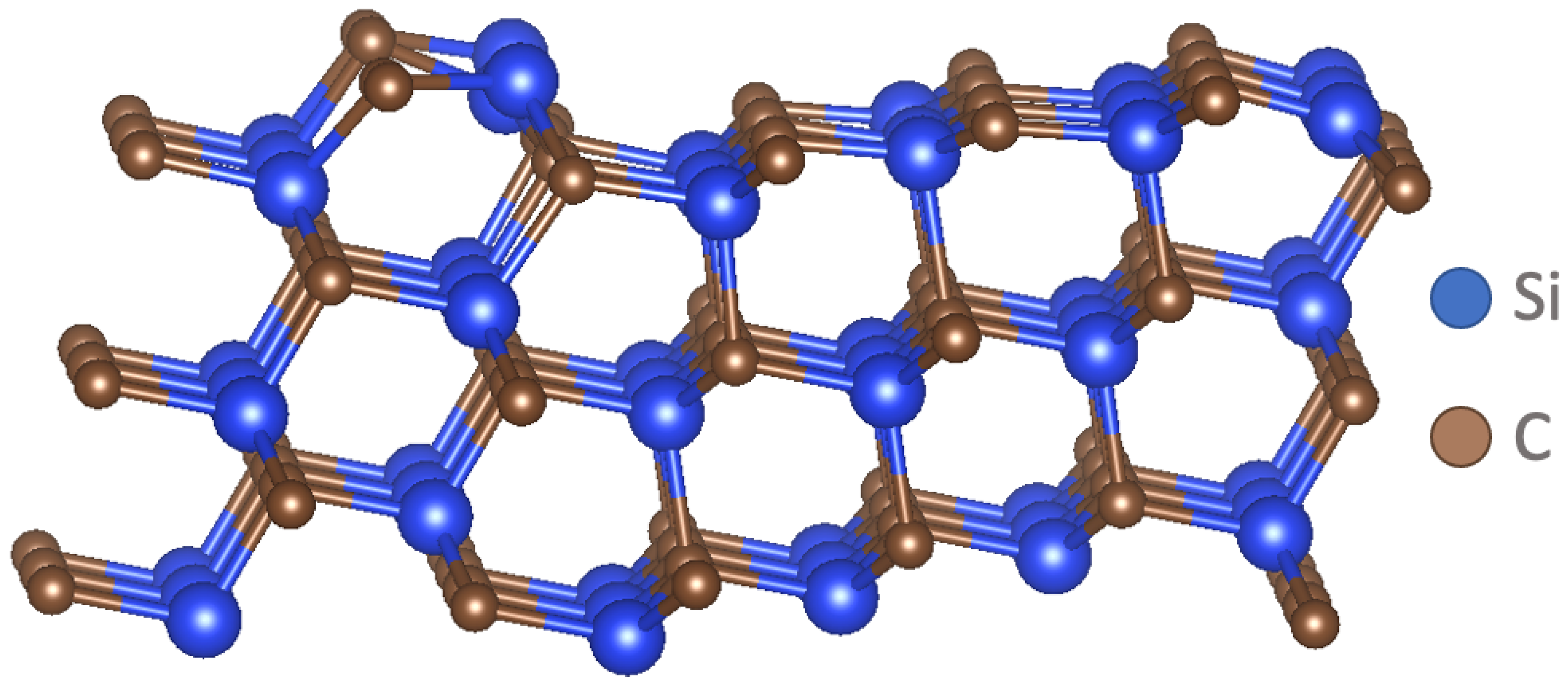
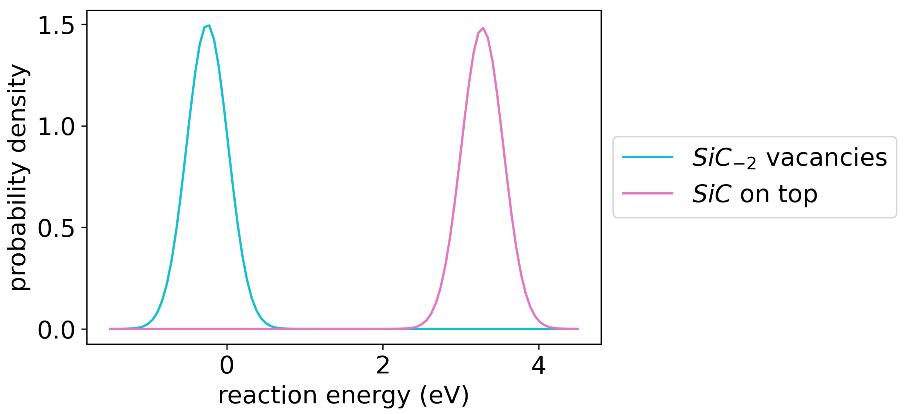
2.1. SiC versus Si Deposition

The overall reaction for MTS deposition on S i C is
C H 3 S i C l 3 + S i C S i C + 3 H C l
The overall reaction is divided into reaction steps that form the reaction mechanism. The full S i C crystal used in DFT calculations is visualized in Figure 1. A thermodynamic evaluation of Si-containing intermediates depositing Si versus S i C is sought [8]. Si is an issue, especially at the matrix–fiber interface, because it weakens the flexural strength of the CMC [4,18]. Si prevents fiber detachment from the matrix and is associated with lower flexural strength. Two intermediates that exist in the gas phase are S i C l 2 (dichlorosilane) [15] and S i C l 3 (trichlorosilane) [12]. The deposition reactions of these two intermediates on Si are visualized in Figure 2. In both reactions, the Si deposits and the Cl react with H to form hydrochloric acid (HCl). The reaction involving S i C l 3 produces more product gas, HCl, than the reaction involving S i C l 2 2 . Equation (2) yields no overall change in the number of gas molecules. The starting two S i C l 2 ( g ) 2 gas molecules and two H 2 ( g ) gas molecules are replaced by four H C l ( g ) gas molecules. Equation (3) yields an increase of one gas molecule. In Equation (3), the starting three S i C l 3 ( g ) gas molecules and two H 2 ( g ) gas molecules are replaced by six H C l ( g ) gas molecules. Notably, an experimental study by Lu et al. [6] identified S i C l 2 2 as a key reaction intermediate. The presence of product gas blocks the transport of reactants into the material coming from the surface. The gases become trapped and form pores when the surface of the material has been sealed upon the completion of the CVI process [19]. The reactions are as follows:
2 S i C l 2 ( g ) 2 + S i + 2 H 2 ( g ) S i + 2 + 4 H C l ( g )
2 S i C l 3 ( g ) + S i + 3 H 2 ( g ) S i + 2 + 6 H C l ( g )
The mechanistic question that these two reactions answer is which intermediate, either dichlorosilane ( S i C l 2 ( g ) 2 ) or trichlorosilane ( S i C l 3 ( g ) ), is more reactive towards depositing on the Si surface.
The same two intermediates, dichlorosilane and trichlorosilane, deposit Si on S i C . A mechanistic possibility is tested by changing the starting state of the S i C surface. Either the Si of dichlorosilane or trichlorosilane can fill either the vacancies of C or Si. The reactions to form C vacancies are
2 S i C l 3 ( g ) + S i 2 C 2 + 3 H 2 ( g ) S i C 2 + 6 H C l ( g )
2 S i C l 2 ( g ) 2 + S i 2 C 2 + 2 H 2 ( g ) S i C 2 + 4 H C l ( g )
In this work, a negative subscript indicates missing atoms relative to a complete slab of 54 C atoms and 54 S atoms. For example, S i C 2 refers to S i 54 C 52 . The reactions to fill Si vacancies are
2 S i C l 3 ( g ) + S i 2 C + 3 H 2 ( g ) S i C + 6 H C l ( g )
2 S i C l 2 ( g ) 2 + S i 2 C + 2 H 2 ( g ) S i C + 4 H C l ( g )
The four reactions of Equations (4)–(7) regarding the deposition of Si on S i C are shown in Figure 3.
The C deposition mechanism is the next piece to address. Sukkaew et al. [14] and Danielsson [16] performed quantum chemical calculations of the CVI reactions using DFT and transition state theory. The active intermediates that participated in deposition were C 2 H 4 , C 2 H 2 , C H 4 , and C H 3 [14]. C 2 H 6 is also a gas-phase intermediate [12]. C H 3 was supported as key species in the experimental work by Lu et al. [6]. C H 4 is then investigated with a transition state search to reveal its mechanism and activation barrier. During reaction, C H 4 transforms to C H 3 and fills a C surface vacancy.
Deposition of C by C 2 H 2 and C 2 H 6 , respectively, are compared in the pore formation section. Two types of mechanisms are considered. One mechanism is the filling of C vacancies. The other mechanism is the forming of Si vacancies. These two intermediates that both deposit two carbons but produce different amounts of H 2 ( g ) show how the final porosity of the material is influenced by the chemistry of the precursor.

2.2. Pore Formation

C 2 H 2 and C 2 H 6 thermodynamic adsorption are computed with DFT to reveal the effect of the C:H ratio on the deposition rate, because C 2 H 2 yields less H 2 than C 2 H 6 and would therefore produce a less porous product. Moreover, less H 2 ( g ) translates to more penetration into the material of the precursor mix, yielding a more uniform porosity distribution and potentially less CVI time. The time of CVI is an important manufacturing consideration [20].
The following CVI reactions are calculated with DFT, beginning with the C 2 H 2 deposition of C:
C 2 H 2 ( g ) + S i C S i C + 2 + H 2 ( g )
C 2 H 2 ( g ) + S i C 2 S i C + H 2 ( g )
The intermediate C 2 H 6 leads to two further unique reactions mirroring the above two reactions. Figure 4 shows the reactions of the C deposition.
C 2 H 6 ( g ) + S i C S i C + 2 + 3 H 2 ( g )
C 2 H 6 ( g ) + S i C 2 S i C + 3 H 2 ( g )
During CVI, S i C is deposited in pores, and the pores at the surface fill before the pores fill in the material [19]. At the surface, the concentration of the precursor mixture is high. Product gases from the reaction in the material decrease the concentration of the precursor mixture in the material, slowing the deposition rate of solid S i C in the material. The precursor mixture must diffuse through the product gases. The result is that the surface seals, effectively ending CVI and leaving pores in the material. One strategy is to decrease the pressure to allow for faster transport out of product gases [20]. However, the downside is that less pressure means less concentration of the precursor mixture and longer time needed to deposit, slowing the manufacturing time. Producing less gas while depositing solid would be advantageous. C 2 H 2 would provide this benefit over C 2 H 6 with an equal deposition rate.

3. Computational Methods

DFT calculations were conducted with the Vienna ab initio simulation Package (VASP) [21]. Plane-wave pseudopotentials represented the core electrons of the nuclei, and the plane wave cutoff for inclusion was 400 eV. The ionic convergence criteria was set to 0.01 eV/Å. The electronic convergence criteria was set to 0.001 eV. The k-points were 4 × 4 × 1 Monkhorst–Pack. Gaussian smearing was used with a width of 0.05 eV.
The Bayesian Error Estimation Functional with van der Waals correction (BEEF-vdW) was used [22]. Furthermore, BEEF-vdW, a generalized gradient approximation functional like PBE, is an appropriate functional for this system considering that the material is not an oxide. BEEF-vdW provides a UQ of its computed energy. The gas molecule entropies were obtained from the National Institute of Standards and Technology Chemistry Webbook (NIST). The entropy of ethane, C 2 H 6 , was not available on NIST and was substituted with the entropy of ethylene, C 2 H 4 . The temperature was set to 1000 °C [4]. The harmonic oscillator approach was used to compute the zero-point energy correction [23].
The transition state searches were conducted with the growing string method [24]. The single-ended string began the transition state searches [25]. Then, to achieve convergence, the double-ended growing string was run from the result of single-ended growing string. The single-ended string may converge on its own. The single-ended string transition state search began with the converged reactant intermediate state. The bond broke, and additions and torsions were set. The single-ended string added nodes or ionic positions along the reaction path, accordingly, and with gradient information from DFT.

4. Results and Discussion

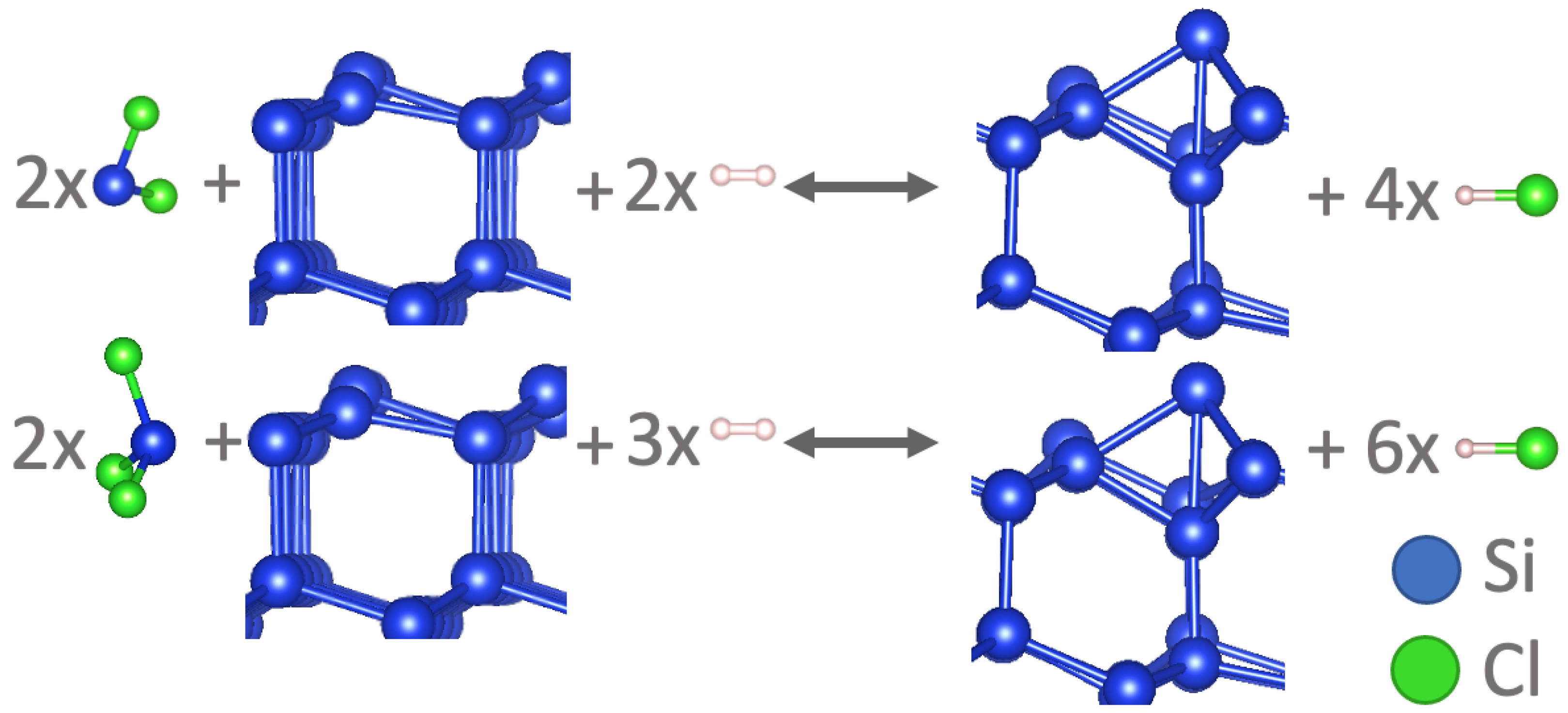
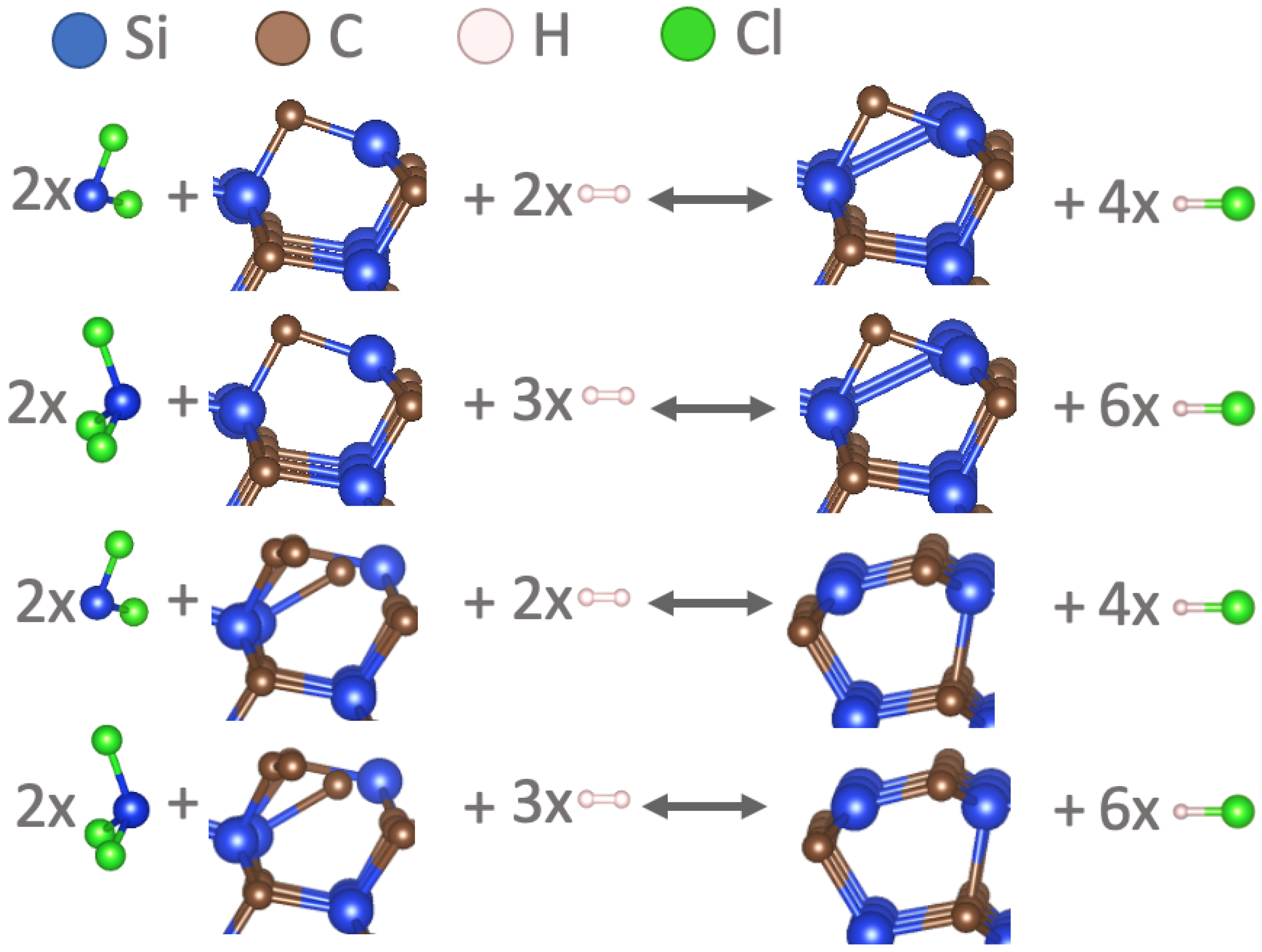
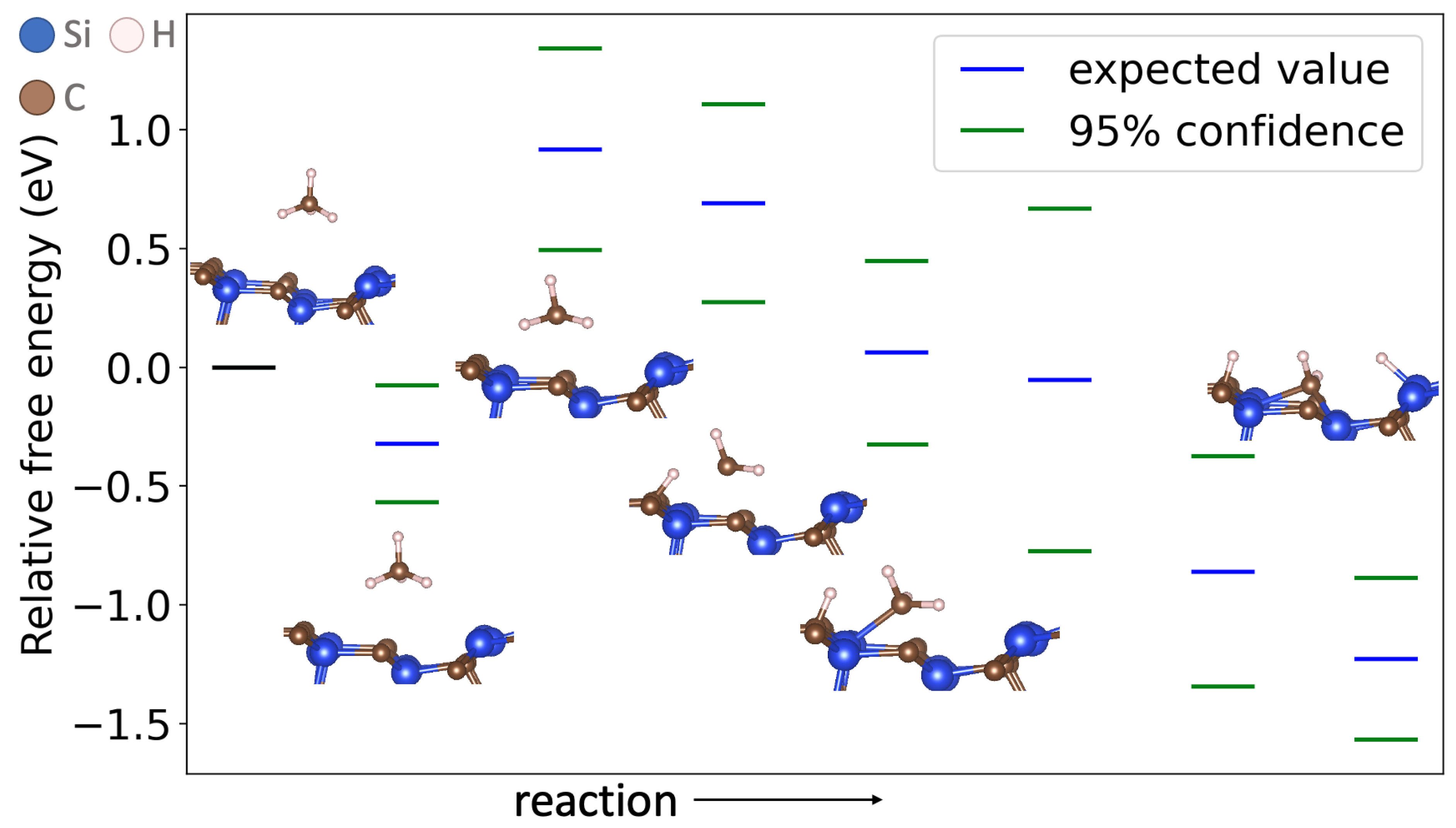
4.1. Reaction Mechanism

All results for the reactions listed in the CVI section are reported in Table 1. The mean energies and standard deviations of each reaction are listed. The first five reactions are C-depositing reactions. Alternately, C-depositing reactions and S-depositing reactions deposit S i C . The first four reactions compare two intermediates, acetylene ( C 2 H 2 ) and ethane ( C 2 H 6 ), depositing into C vacancies or depositing to create Si vacancies, and those are relevant to pore formation. The methane ( C H 4 ) deposition reaction is into a C vacancy. The remaining reactions are Si-depositing. Si reactions are for S i C and Si (solid phase).
The results for the two intermediates related to pore formation are visualized in Figure 5. Their reactions deposit the same amount of C but produce differing quantities of product gas. One may see that, despite ethane being favored over acetylene, the uncertainty overlaps considerably (Figure 5). The two intermediates are essentially competitive in adsorption. Therefore, acetylene would be preferred to adsorb because it produces less product gas and would lead to less porosity in the final material. By producing less product gas, more precursor gas is able to transport into the material. With more precursor gas in the material, the solid deposition rate increases, decreasing porosity.
Figure 5 is contrasted with Figure 6, where there is a clear difference in thermodynamic distinction. C 2 H 6 prefers to deposit C in vacancies rather than on top of a complete S i C surface. This difference could be attributed to the instability of the S i C vacancy structure. The significance is that the C deposition rate controls the growth of solid S i C . Excess C is not deposited on filled S i C surfaces due to not being thermodynamically favorable (results in Table 1).

4.2. Methane Deposition

The methane ( C H 4 ) deposition reaction converged to an exact transition state. C H 3 is a molecule formed along the reaction coordinate [6,14]. The free energy profile, including uncertainty quantification from BEEF-vdW and key structures, are shown in Figure 7. The activation barrier is from the first C-H bond breaking. The other C-H bond-breaking steps do not exhibit activation barriers with the possible exception of the second C-H bond breaking. There might be an activation barrier but the margin is within the uncertainty of the DFT. DFT errors tend to be correlated [26,27]. Therefore, the overall transition state has a strong probability as predicted by DFT of being the first C-H bond breaking in spite of the overlap of the 95% confidence intervals as the reaction proceeds, due to the correlation effect. The Hs adsorb on both C and S in the final state. These mechanistic results are consistent with C H 3 being an important and active intermediate that deposits C [14].

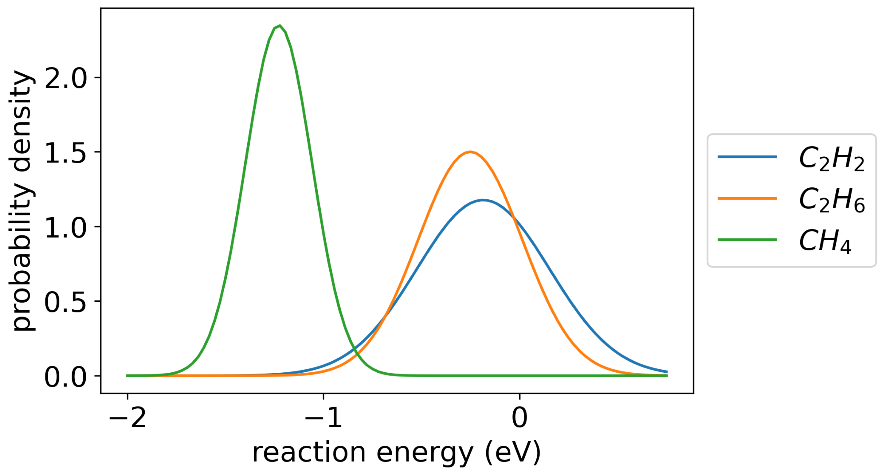
4.3. Summary of Thermodynamics

Figure 8 shows the order of thermodynamic favorability of the CVI reactions. Moreover, it shows the amount of product gas leading to porosity. Acetylene is the least thermodynamically favorable reaction, yet it produces the least hydrogen gas and, therefore, the least final porosity while being of similar thermodynamic favorability as ethane. Ethane produces the most product gas to yield the most final porosity. Both of these C2 intermediates prefer to fill C vacancies formed by strongly-depositing Si. Methane is the most favorable intermediate for depositing C, and it is an intermediate producer of pores compared with acetylene and ethane. Si deposition in general is more favorable than C deposition. Si deposition on either surface produces twice as much product gas as it consumes. Si most favorably deposits on S i C ; however, Si favorably deposits on Si than C deposits on S i C , leading to Si deposits. Notably, S i C l 2 produces less product gas than S i C l 3 and is less reactive.

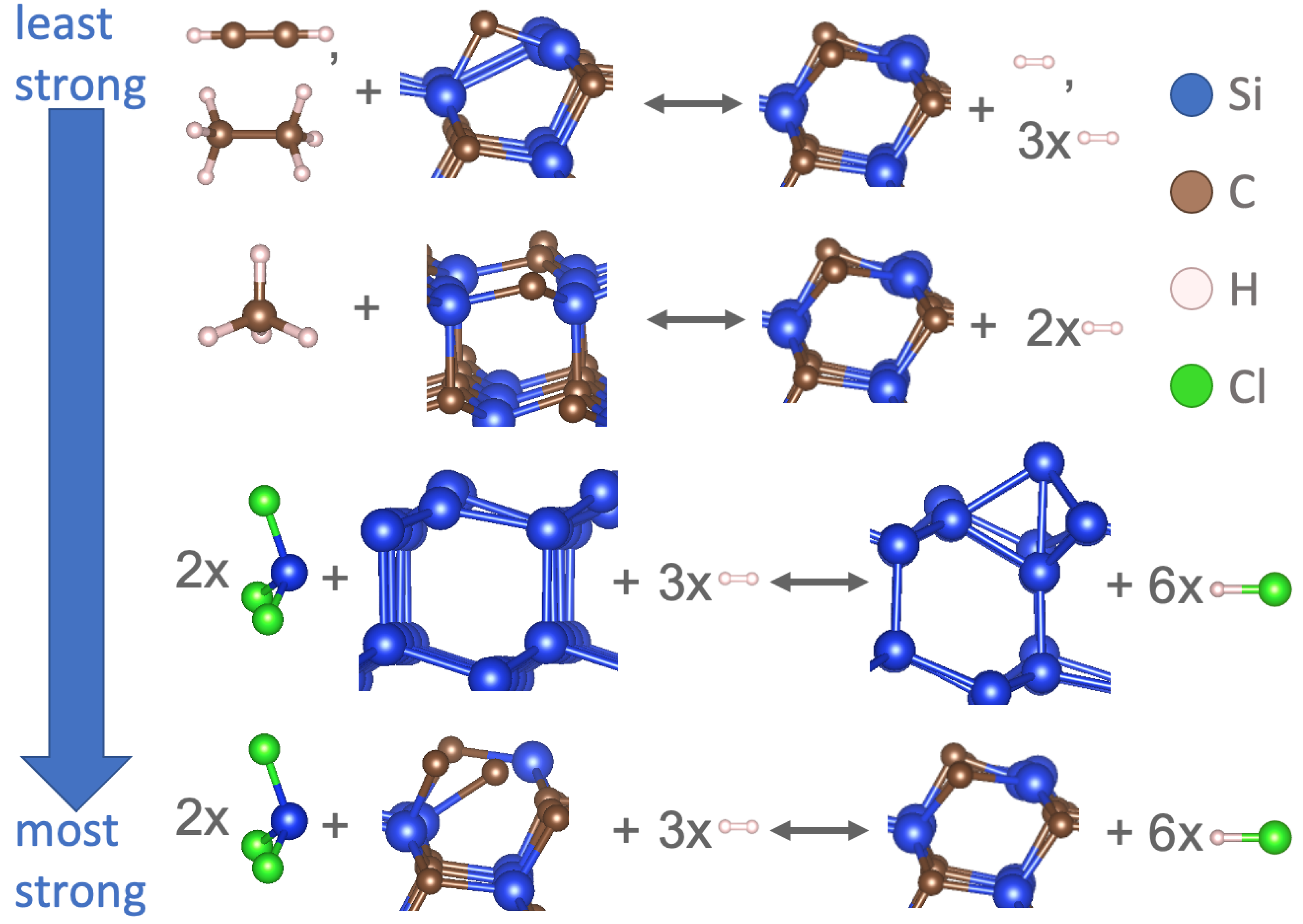
4.4. Chemical Precursor Suggestions

The most significant strategy is to add C H 4 to the chemical precursor, as this molecule is the most reactive for depositing C. In general, extra hydrocarbon species [28] in the precursor mix to increase the C:Si ratio helps. Depositing C increases the rate of CVI and also decreases the fraction of undesirable solid Si forming. The speed of the CVI process matters in manufacturing [20]. The chlorosilane intermediates are more reactive than hydrocarbon intermediates, both supported by literature and DFT calculations here [8,29,30]. For this reason, HCl [31] has been added to abate Si growth [8]. It is a worthwhile strategy given the reaction mechanism. HCl is a product of the Si growth reactions, and adding more of the HCl product drives the reaction back towards the reactants. Moreover, if S i C l 2 is increased in the precursor mix to the exclusion of S i C l 3 , the result would be less Si deposits and less porosity.
Porosity from CVI is due in most part to the gaseous reaction products. The idea that acetylene adsorbs as readily as ethane can lead to a chemical precursor strategy to reduce the amount of gases produced. An example is vinyltrichlorosilane (VTS, C 2 H 3 S i C l 3 ) [8]. There is more carbon and less hydrogen in this precursor. For every carbon deposited, less gaseous hydrogen is released in contrast to MTS ( C H 3 S i C l 3 ).

5. Conclusions

The key reaction mechanism steps of the Chemical Vapor Infiltration (CVI) of silicon carbide ceramic matrix composites (CMCs) have been computed using density functional theory (DFT). The goal and outcome were to provide guidance on chemical precursor choice. DFT has provided the foundational chemical insight. Si deposition on S i C is favored to Si deposition on Si. Nonetheless, Si deposition of any kind is thermodynamically favorable to C deposition. Therefore, any strategy to increase the amount of C relative to Si in the precursor mix is beneficial. C H 4 is thermodynamically favored to the other C-containing intermediates computed here and is suggested as an addition to the chemical precursor. Should decreasing porosity be the priority, more than Si mitigation and speed, using a precursor with a high C:H ratio is suggested, such as vinyltrichlorosilane (VTS, C 2 H 3 S i C l 3 ). Any strategy to maximize dichlorosilane ( S i C l 2 ) and minimize trichlorosilane ( S i C l 3 ) is beneficial for both mitigating Si deposits and decreasing porosity.
During CVI, the precursor mix penetrates inside the pores of the material yet loses concentration the deeper it penetrates. The loss of precursor concentration is due to being consumed by reaction and also the filling of the pores by the gaseous reaction product. Therefore, in future work, a combined reaction and transport model will be made to predict the results of the CVI process.

Author Contributions

E.A.W. originates the idea for this manuscript. J.J.M. assist in the code development and run cases with E.A.W. and J.C. participated with the analysis. All three authors collaborate on composing and finalizing this manuscript. All authors have read and agreed to the published version of the manuscript.

Funding

Funding for this project was provided, in part, by LIFT, the Detroit-based national manufacturing innovation institute operated by ALMMII, the American Lightweight Materials Manufacturing Innovation Institute, a Michigan-based nonprofit, 501(c)3 as part of the ONR Grant N00014-21-1-2660.

Institutional Review Board Statement

Not applicable for our study.

Informed Consent Statement

Not applicable for our study.

Data Availability Statement

Data related to this study is available upon request to the corresponding author.

Conflicts of Interest

The authors declare no conflict of interest.

References

  1. An, Q.; Chen, J.; Ming, W.; Chen, M. Machining of SiC ceramic matrix composites: A review. Chin. J. Aeronaut. 2021, 34, 540–567. [Google Scholar] [CrossRef]
  2. Nagaraju, H.T.; Nance, J.; Kim, N.H.; Sankar, B.; Subhash, G. Uncertainty quantification in elastic constants of SiCf/SiCm tubular composites using global sensitivity analysis. J. Compos. Mater. 2023, 57, 63–78. [Google Scholar] [CrossRef]
  3. Kakanakova-Georgieva, A.; Ivanov, I.G.; Suwannaharn, N.; Hsu, C.-W.; Cora, I.; Pécz, B.; Giannazzo, F.; Sangiovanni, D.G.; Gueorguiev, G.K. MOCVD of AlN on epitaxial graphene at extreme temperatures. CrystEngComm 2021, 23, 385–390. [Google Scholar] [CrossRef]
  4. Arai, Y.; Inoue, R.; Goto, K.; Kogo, Y. Carbon fiber reinforced ultra-high temperature ceramic matrix composites: A review. Ceram. Int. 2019, 45, 14481–14489. [Google Scholar] [CrossRef]
  5. Fédou, R.; Langlais, F.; Naslain, R. A Model for the Isothermal Isobaric Chemical Vapor Infiltration (CVI) in a Straight Cylindrical Pore. Application to the CVI of SiC. J. Mater. Synth. Process. 1993, 1, 61–74. [Google Scholar]
  6. Lu, C.; Cheng, L.; Zhao, C.; Zhang, L.; Xu, Y. Kinetics of chemical vapor deposition of SiC from methyltrichlorosilane and hydrogen. Appl. Surf. Sci. 2009, 255, 7495–7499. [Google Scholar] [CrossRef]
  7. Vignoles, G. Advances in Composites Manufacturing and Process Design; Woodhead Publishing: Cambridge, UK, 2015; pp. 415–458. [Google Scholar]
  8. Desenfant, A.; Laduye, G.; Vignoles, G.; Chollon, G. Kinetic and gas-phase study of the chemical vapor deposition of silicon carbide from C2H3SiCl3/H2. J. Ind. Eng. Chem. 2021, 94, 145–158. [Google Scholar] [CrossRef]
  9. Snead, M.A.; Katoh, Y.; Koyanagi, T.; Singh, G.P. SiC/SiC Cladding Materials Properties Handbook; Oak Ridge National Lab. (ORNL): Oak Ridge, TN, USA, 2017. [Google Scholar]
  10. Ge, Y.; Gordon, M.S.; Battaglia, F.; Fox, R.O. Theoretical Study of the Pyrolysis of Methyltrichlorosilane in the Gas Phase. 1. Thermodynamics. J. Phys. Chem. A 2007, 111, 1462–1474. [Google Scholar] [CrossRef]
  11. Ge, Y.; Gordon, M.S.; Battaglia, F.; Fox, R.O. Theoretical Study of the Pyrolysis of Methyltrichlorosilane in the Gas Phase. 2. Reaction Paths and Transition States. J. Phys. Chem. A 2007, 111, 1475–1486. [Google Scholar] [CrossRef]
  12. Ge, Y.; Gordon, M.S.; Battaglia, F.; Fox, R.O. Theoretical Study of the Pyrolysis of Methyltrichlorosilane in the Gas Phase. 3. Reaction Rate Constant Calculations. J. Phys. Chem. A 2010, 114, 2384–2392. [Google Scholar] [CrossRef]
  13. Allendorf, M.D.; Kee, R.J. A Model of Silicon Carbide Chemical Vapor Deposition. J. Electrochem. Soc. 1991, 138, 841. [Google Scholar] [CrossRef]
  14. Sukkaew, P.; Danielsson, O.; Kordina, O.; Janzen, E.; Ojamae, L. Ab Initio Study of Growth Mechanism of 4H–SiC: Adsorption and Surface Reaction of C2H2, C2H4, CH4, and CH3. J. Phys. Chem. C 2017, 121, 1249–1256. [Google Scholar] [CrossRef]
  15. Sukkaew, P.; Kalered, E.; Janzen, E.; Kordina, O.; Danielsson, O.; Ojamae, L. Growth mechanism of SiC chemical vapor deposition: Adsorption and surface reactions of active Si species. J. Phys. Chem. C 2018, 122, 648–661. [Google Scholar] [CrossRef]
  16. Danielsson, O.; Karlsson, M.; Sukkaew, P.; Pedersen, H.; Ojamae, L. A Systematic Method for Predictive In Silico Chemical Vapor Deposition. J. Phys. Chem. C 2020, 124, 7725–7736. [Google Scholar] [CrossRef]
  17. Sangiovanni, D.G.; Faccio, R.; Gueorguiev, G.K.; Kakanakova-Georgieva, A. Discovering atomistic pathways for supply of metal atoms from methyl-based precursors to graphene surface. Phys. Chem. Chem. Phys. 2023, 25, 829–837. [Google Scholar] [CrossRef]
  18. Hussey, A.; De Meyere, R.; Deck, C.; Armstrong, D.; Zayachuk, Y. Statistically sound application of fiber push-out method for the study of locally non-uniform interfacial properties of SiC-SiC fiber composites. J. Eur. Ceram. Soc. 2020, 40, 1052–1056. [Google Scholar] [CrossRef]
  19. Cha, C.M.; Liliedahl, D.; Sankaran, R.; Ramanuj, V. Microstructural and infiltration properties of woven preforms during chemical vapor infiltration. J. Am. Ceram. Soc. 2022, 105, 4595–4607. [Google Scholar] [CrossRef]
  20. Petroski, K.; Poges, S.; Monteleone, C.; Grady, J.; Bhatt, R.; Suib, S. Rapid Chemical Vapor Infiltration of Silicon Carbide Minicomposites at Atmospheric Pressure. ACS Appl. Mater. Interfaces 2018, 10, 4986–4992. [Google Scholar] [CrossRef]
  21. Kresse, G.; Furthmüller, J. Efficient iterative schemes for ab initio total-energy calculations using a plane-wave basis set. Phys. Rev. B 1996, 54, 11169–11186. [Google Scholar] [CrossRef]
  22. Wellendorff, J.; Lundgaard, K.T.; Møgelhøj, A.; Petzold, V.; Landis, D.D.; Nørskov, J.K.; Bligaard, T.; Jacobsen, K.W. Density functionals for surface science: Exchange-correlation model development with Bayesian error estimation. Phys. Rev. B 2012, 85, 235149. [Google Scholar] [CrossRef]
  23. Canavan, J.; Giewont, K.; Kyriakidou, E.A.; Walker, E.A. Feasibility of Methane Oxidation on SSZ-13 Bridged Pd2Ox Sites: A Theoretical Study. J. Phys. Chem. C 2022, 126, 17123–17134. [Google Scholar] [CrossRef]
  24. Jafari, M.; Zimmerman, P.M. Reliable and efficient reaction path and transition state finding for surface reactions with the growing string method. J. Comput. Chem. 2017, 38, 645–658. [Google Scholar] [CrossRef]
  25. Zimmerman, P.M. Single-ended transition state finding with the growing string method. J. Comput. Chem. 2015, 36, 601–611. [Google Scholar] [CrossRef]
  26. Walker, E.; Ammal, S.C.; Terejanu, G.A.; Heyden, A. Uncertainty quantification framework applied to the water–gas shift reaction over Pt-based catalysts. J. Phys. Chem. C 2016, 120, 10328–10339. [Google Scholar] [CrossRef]
  27. Medford, A.J.; Wellendorff, J.; Vojvodic, A.; Studt, F.; Abild-Pedersen, F.; Jacobsen, K.W.; Bligaard, T.; Nørskov, J.K. Assessing the reliability of calculated catalytic ammonia synthesis rates. Science 2014, 345, 197–200. [Google Scholar] [CrossRef]
  28. Kim, J.I.; Kim, W.-J.; Choi, D.J.; Park, J.Y. Deposition of compositionally graded SiC/C layers on C–C composites by low pressure chemical vapor deposition. J. Nucl. Mater. 2002, 307–311, 1084–1087. [Google Scholar] [CrossRef]
  29. Loumagne, F.; Langlais, F.; Naslain, R.; Schamm, S.; Dorignac, D.; Sévely, J. Physicochemical properties of SiC-based ceramics deposited by low pressure chemical vapor deposition from CH3SiCl3H2. Thin Solid Films 1995, 254, 75–82. [Google Scholar] [CrossRef]
  30. Papasouliotis, G.D.; Sotirchos, S.V. Experimental study of atmospheric pressure chemical vapor deposition of silicon carbide from methyltrichlorosilane. J. Mater. Res. 1999, 14, 3397–3409. [Google Scholar] [CrossRef]
  31. Lespiaux, D.; Langlais, F.; Naslain, R.; Schamm, S.; Sevely, J. Chlorine and oxygen inhibition effects in the deposition of SiC-based ceramics from the Si C H Cl system. J. Eur. Ceram. Soc. 1995, 15, 81–88. [Google Scholar] [CrossRef]
Figure 1. Full S i C crystal cells used in DFT calculations. The vacancy occurs at the surface.
Methane 02 00028 g001
Figure 2. Reactions that deposit Si on Si.
Methane 02 00028 g002
Figure 3. Reactions that deposit Si on S i C .
Methane 02 00028 g003
Figure 4. Reactions that deposit carbon. (a) Two C from ethylene are deposited on a S i C surface. (b) Two C from ethylene are deposited into two C vacancies of the S i C surface. (c) Two C from ethane are deposited on a S i C surface, yielding more hydrogen gas. (d) Two C from ethane are deposited into two C vacancies of the S i C surface, yielding more hydrogen gas.
Methane 02 00028 g004
Figure 5. Uncertainty quantification of deposition of ethane, C 2 H 6 , and acetylene, C 2 H 2 , into the carbon vacancies in silicon carbide, S i C .
Methane 02 00028 g005
Figure 6. Uncertainty quantification of deposition of ethane, C 2 H 6 , onto C vacancies in a S i C surface versus on top of a S i C surface.
Methane 02 00028 g006
Figure 7. Methane deposition on S i C free energy including transition state (T = 1000 °C). The mean activation barrier is 0.918 (eV), with an upper bound of 1.342 and a lower bound of 0.493. The standard deviation is 0.212.
Methane 02 00028 g007
Figure 8. Summary of thermodynamic findings for CVI.
Methane 02 00028 g008
Table 1. DFT results.
Reaction EquationReaction Energy (eV)Standard Deviation (eV)
C 2 H 2 ( g ) + S i C S i C + 2 + H 2 ( g ) 3.3440.296
C 2 H 2 ( g ) + S i C 2 S i C + H 2 ( g ) −0.1850.339
C 2 H 6 ( g ) + S i C S i C + 2 + 3 H 2 ( g ) 3.2780.269
C 2 H 6 ( g ) + S i C 2 S i C + 3 H 2 ( g ) −0.2510.266
C H 4 ( g ) + S i C 1 S i C + 3 H * −1.2280.170
2 S i C l 2 ( g ) 2 + S i 2 C 2 + 2 H 2 ( g ) S i C 2 + 4 H C l −13.8931.309
2 S i C l 3 ( g ) + S i 2 C 2 + 3 H 2 ( g ) S i C 2 + 6 H C l −22.4091.480
2 S i C l 2 ( g ) 2 + S i 2 C + 2 H 2 ( g ) S i C + 4 H C l −16.0201.463
2 S i C l 3 ( g ) + S i 2 C + 3 H 2 ( g ) S i C + 6 H C l −24.5361.586
2 S i C l 2 ( g ) 2 + S i 2 + 2 H 2 ( g ) S i + 4 H C l −8.9471.389
2 S i C l 3 ( g ) + S i + 3 H 2 ( g ) S i + 2 + 6 H C l −17.4631.568
Disclaimer/Publisher’s Note: The statements, opinions and data contained in all publications are solely those of the individual author(s) and contributor(s) and not of MDPI and/or the editor(s). MDPI and/or the editor(s) disclaim responsibility for any injury to people or property resulting from any ideas, methods, instructions or products referred to in the content.

