Review

Impact of Niobium Reduction on the Microstructure and Properties of Alloy 625 Weld Overlay Claddings: A Review

by
Reylina Garcia Tayactac
1,2,*,
Mark Christian E. Manuel
1,2,
Jaime P. Honra
1,2,
Tiago Bohn Kaspary
3 and
Raimundo Cabral de Medeiros
4
1
School of Mechanical, Manufacturing and Energy Engineering, Mapúa University, Manila 1002, Philippines
2
School of Graduate Studies, Mapúa University, Manila 1002, Philippines
3
Cladtek do Brasil, Rio de Janeiro 23565-170, Brazil
4
Consórcio Ocyan & Mota-Engil Malha de Gas, Rio de Janeiro 27925-405, Brazil
*
Author to whom correspondence should be addressed.
Alloys 2025, 4(3), 12; https://doi.org/10.3390/alloys4030012
Submission received: 29 April 2025 / Revised: 30 May 2025 / Accepted: 27 June 2025 / Published: 2 July 2025

Abstract

Alloy 625 is a widely utilized nickel-based superalloy known for its excellent mechanical strength and corrosion resistance in aggressive environments. However, its high niobium (Nb) content can lead to the formation of detrimental phases, such as Laves and MC carbides, during welding processes, compromising the mechanical integrity and long-term performance of the weld overlay. This review systematically examines recent research findings on the implications of reducing Nb content in Alloy 625 weld overlays, particularly with respect to microstructure evolution, mechanical behavior, and corrosion performance. Key advancements, including the understanding of segregation behavior, solidification paths, and secondary phase formation, are presented based on recent studies. This paper aims to provide a discussion on the trade-offs and future directions for optimizing Alloy 625 weld overlay claddings through Nb content modification.

1. Introduction

Alloy 625 (UNS N06625) is a nickel-based superalloy that was developed in the 1950s to meet the demanding mechanical and corrosion performance requirements of supercritical steam power systems [1,2,3]. Since then, it has found widespread use across numerous industries, including oil and gas, chemical processing, marine, aerospace, and power generation, due to its excellent strength, fatigue resistance, and corrosion performance in aggressive environments [1,2,4,5].
The superior performance of Alloy 625 is attributed to its carefully balanced chemical composition. Solid solution strengthening is primarily driven by chromium (Cr) and molybdenum (Mo), while niobium (Nb) plays a dual role, as it contributes to strength enhancement through matrix reinforcement and, under specific thermal conditions, promotes precipitation hardening via phases such as γ″ (Ni3Nb) [1,2]. Additionally, niobium, along with Mo and Cr, enhances the alloy’s creep resistance and high-temperature mechanical properties [1,2,4].
This alloy also contains trace amounts of aluminum and titanium, which are added mainly for refining purposes [1]. These elements are typically kept lower than in similar alloys, such as Alloy 718, to improve weldability [1,4]. However, if sufficient amounts of niobium, aluminum, and titanium are present, then precipitation hardening may occur [3]. It is the high levels of chromium and molybdenum that provide Alloy 625 with its excellent resistance to corrosion [1,3,6].
Despite its beneficial effects, the presence of niobium may pose challenges to Alloy 625’s weldability [1,2,6]. During welding or post-weld thermal exposure, Nb tends to segregate into inter-dendritic regions, leading to the formation of secondary phases such as Laves and MC-type carbides. These phases are brittle and can degrade the ductility, toughness, and corrosion resistance of the weld overlay, compromising the long-term reliability of clad components [5].
This paper aims to review the effects of reducing niobium content on Alloy 625 weld overlay cladding. It investigates the influence of niobium on the alloy’s microstructure, mechanical properties, corrosion resistance, and overall performance [5,7]. Reducing niobium content may potentially prevent the formation of detrimental phases, such as Laves and Carbides, thereby improving the material’s long-term performance [8]. Research indicates that niobium additions to steel alloys enhance overall performance by influencing the relationship between composition, processing, microstructure, and mechanical properties [1,2,5,9]. Further studies examining the impact of reduced niobium on Alloy 625’s phase composition provide insights into balancing mechanical properties with corrosion resistance [5,10].
By systematically analyzing the current literature, this review outlines the benefits, challenges, and potential future directions in modifying the niobium content of Alloy 625 weld overlay claddings. These insights are crucial for developing improved cladding materials capable of meeting industry demands for enhanced performance characteristics [1,2,5]. This review is grounded in research surrounding the invention and development of Alloy 625, based on studies by Eiselstein and Tillack [2], who investigated the role of alloying elements in strengthening and improving creep resistance, as well as the impact of heat treatments on the final properties of Alloy 625.

2. Historical Development and Alloy Design

Alloy 625 (UNS N06625) was originally developed by Inco Alloys International, Inc., in the 1950s as a high-strength alternative to Type 316 stainless steel for use in supercritical steam power plants [2]. A key requirement for its intended application was not only mechanical strength but also metallurgical stability, which is the ability of the alloy to retain its properties under prolonged high-temperature service conditions [2].
Initial research focused on the roles of chromium (Cr), molybdenum (Mo), niobium (Nb), aluminum (Al), and titanium (Ti) as strengthening elements [1,2,4]. However, the individual effects of these elements were found to be limited. This led to investigations on their combined influence, particularly the interactions between Nb and Mo at various nickel (Ni) concentrations. Tensile tests after aging treatments at 704 °C for 16 h revealed that strength was particularly improved by the precipitation of secondary phases such as γ″ (Ni3Nb) in compositions containing 6.5% Nb and 3% Mo, especially after annealing and aging, where yield strength exceeded 1100 MPa [2]. This can be seen in Figure 1.
Conversely, alloys with lower Nb and Mo contents (e.g., 4.5% Nb + 2% Mo) exhibited significantly lower yield strengths, remaining below 500 MPa in the annealed-only condition. Increasing nickel content to approximately 50–55% further promoted yield strength under both annealed and aged conditions, highlighting Ni’s role in enhancing solid solution strengthening and stabilizing the austenitic matrix [11].
Post-annealing aging treatments were shown to be critical in achieving optimal mechanical properties. The precipitation of strengthening phases such as γ″ significantly contributes to Alloy 625’s mechanical performance [2]. However, the benefits of Nb must be balanced carefully, as excessive Nb content can decrease ductility, making composition control and appropriate heat treatment essential in cladding applications [5,7].
The development of Alloy 625 was temporarily halted as attention shifted to Alloy 718 [2]. When work resumed, demand for nickel-based alloys in supercritical steam applications had decreased. At that time, the alloy contained about 60% nickel, 15% chromium, 3% niobium, 2% molybdenum, 0.5% aluminum, 0.5% titanium, and the balance iron [2]. In its annealed state, its strength was only slightly better than Alloy 600 (UNS N06600), offering limited performance improvements [2].
To improve both strength and corrosion resistance, Cr and Mo contents increased to 22% and 9%, respectively. These modifications greatly enhanced the alloy’s versatility and enabled its adoption across various industries, including aerospace, chemical processing, and marine environments [2,5]. A patent application for Alloy 625 was filed on January 24, 1962, and was later granted to Eiselstein and Gadbut under U.S. Patent No. 3160500 [2]. Since then, the alloy’s composition has been refined slightly, with the current composition listed in Table 1 [12].
Even as the steam market declined, Alloy 625’s development continued, with emphasis on improving high-temperature performance [2,5]. Figure 2a illustrates the effect of Ni on 1000 h stress rupture strength at 649 °C, showing a peak around 57% Ni. Figure 2b shows that Nb has little effect below 2% in the annealed state but significantly boosts strength when increased above 3%, aligning with Nb’s solubility limit around 2.5% [5,13].
The alloy’s design involved important trade-offs. While molybdenum improved solid solution strength, it also unexpectedly contributed to increased age hardening. Whether this effect is due to Mo alone or its interaction with Nb is still unclear. An increase in Cr content to 22% improved solid solution strength but did not significantly affect age hardening. Mo, Cr, and especially Nb are known to enhance creep resistance, as illustrated in Figure 3a,b [11].

3. Metallurgical Challenges of Alloy 625

Alloy 625 was initially designed as a solid solution alloy, and for most uses, it functions as one [13]. It is marketed based on its strength derived from molybdenum and niobium reinforcing its nickel-chromium base, eliminating the need for precipitation-hardening treatments [13,14].
During the development phase, it was found that prolonged exposure to temperatures near 650 °C could induce age hardening, likely as a result of the precipitation of the Ni3 (Ti, Al) based gamma prime (γ’) phase [1,2]. These extended exposure times much longer than the original; 16 h tests revealed that the alloy could indeed age harden but only after impractically long durations, such as 200 h at 649 °C [2]. Furthermore, as discussed later, the formation of γ’ was not considered beneficial [1].
In the mid-to-late 1960s, interest emerged in developing large cross-section components of Alloy 625 (200–250 mm diameter) with a minimum yield strength of 552 MPa [2]. While increasing the niobium content to 4% or more was proposed by Knolls Atomic Power Laboratory (KAPL), Inco preferred to achieve the required strength through controlled thermomechanical processing and heat treatment. They reasoned that a higher-niobium variant would introduce commercial complications such as inventory duplication, fragmented market demand, and manufacturing difficulties, including increased segregation during melting, reduced workability during forming, and lower product yields due to elevated levels of niobium carbide precipitates [2].
Earlier lab studies showed that large sections needed a final thermal processing step for the desired yield strength. Thermal strengthening was effective but slow, occurring around 649 °C with the greatest response within 48 h [2]. Warm work helped, but inhomogeneous strain could cause property variations. Annealing at 871–927 °C was crucial for achieving the minimum 414 MPa yield strength, with additional aging at 649 °C for 24–48 h needed to reach 552 MPa [2].
The face-centered cubic (FCC) γ’ phase is unstable between 600 °C and 850 °C, transforming into the hexagonal close-packed (HCP) η phase. This transformation may partly explain poor creep test results before aluminum and titanium levels were controlled. For applications below 650 °C, the body-centered tetragonal (BCT) gamma double prime (γ”) phase, typically Ni3Nb [15], is used to strengthen nickel-based superalloys [16].
In smaller specimens (up to 100 mm diameter), annealing temperature critically affects aging response, with higher temperatures leading to a poorer response to direct aging. In larger specimens (up to 250 mm diameter), annealing temperature is less critical due to slower cooling, allowing more time in the 732–843 °C nucleation range. This triggers precipitation and faster growth of subcritical γ” nuclei, enabling normal, though slow, γ” precipitation during aging at 649 °C. A 2–4 min dwell time in the critical 760–788 °C range seems necessary for faster aging at 649 °C [2].
If smaller specimens are annealed at high temperatures like 1149 °C, an intermediate 760 °C nucleation treatment for 1 h is needed before aging to achieve timely hardening at 649 °C. Figure 4 compares the aging times needed for appreciable hardening. After 1149 °C annealing, the sample without nucleation showed no hardness increase after 96 h at 649 °C, while the nucleated sample increased by 11 Rockwell ‘A’ points. The levels of aluminum and titanium were deliberately limited to reduce the alloy’s susceptibility to age hardening. However, creep tests conducted at 649 °C demonstrated a significant advantage in maintaining approximately 0.2% of each of these elements. Furthermore, a lower combined content of aluminum and titanium contributed to improved weldability. Especially, the solubility of aluminum within the alloy was established to be around 0.5% [17,18].
By managing aluminum and titanium levels, Alloy 625 avoids precipitating γ’ (common in AI-Ti hardened alloys) and instead forms metastable γ” and stable orthorhombic Ni3Nb phases [11,17,19]. The γ” phase provides the most strength and is key for age hardening [13,16]. The orthorhombic Ni3Nb phase, not coherent with the matrix, contributes to hardening only as a dispersant [5,20].
After a solution annealing (at least 1093 °C), Alloy 625’s yield strength should be at least 276 MPa [2]. While 414 MPa and 345 MPa are achievable in cross-sections up to 100 mm and 100–250 mm, respectively, higher minimums without extensive mechanical working require prolonged age hardening, like 24–48 h at 649 °C [2]. Figure 5 shows room temperature yield strength after varying exposure times up to 1000 h at intermediate temperatures [2].
The balance of aluminum, titanium, and niobium is critical in managing the alloy’s age-hardening behavior. While higher niobium content improves this hardening, it can also compromise room-temperature ductility, particularly after prolonged exposure to intermediate temperatures [7]. In such scenarios, the gains in age hardening may be offset by the loss of ductility at normal temperatures [7].
Removing niobium from alloys can offer several benefits, particularly in terms of economic savings, improved weldability, and simplified processing. Niobium is a critical and strategic metal with high economic importance, and its supply is limited, primarily dominated by Brazil [21,22]. The high cost of niobium makes its removal economically beneficial for industries looking to reduce production costs [22].
Niobium is not typically added to ferritic steels to improve weldability; instead, it is used for its beneficial effects on strength and toughness [23]. However, high levels of niobium can introduce weldability issues, such as the formation of undissolved niobium particles and increased mill loads, which can negatively impact the welding process [24,25]. Removing niobium can thus mitigate these issues and improve the overall weldability of the alloy.
The presence of niobium in alloys can complicate the processing into finished products like wire, plate, and pipe. Niobium’s role in enhancing mechanical properties often requires precise thermo-mechanical control, which can be challenging to implement consistently [24]. By removing niobium, the processing steps can be simplified, leading to enhanced efficiency and reduced complexity in manufacturing.

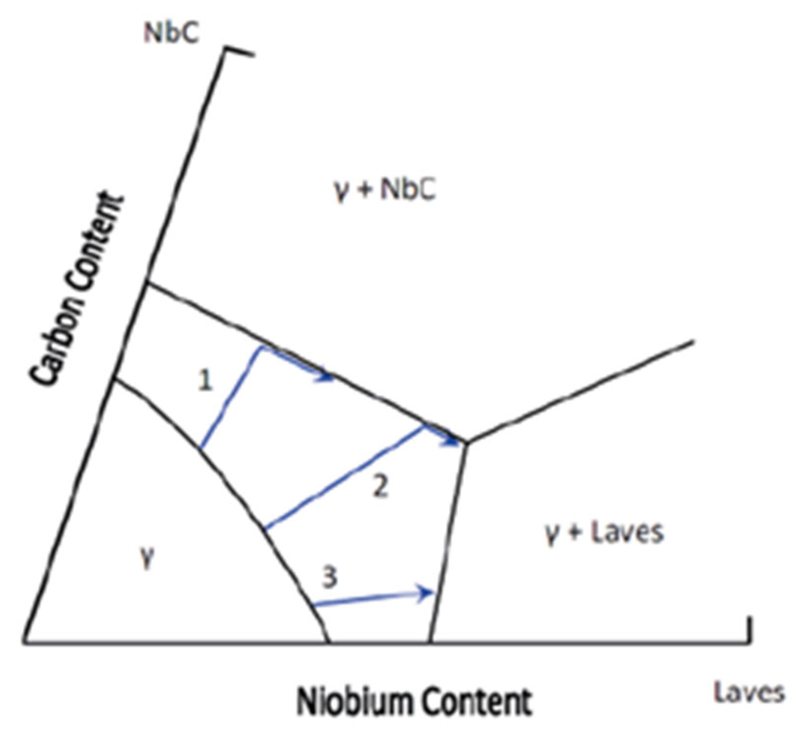
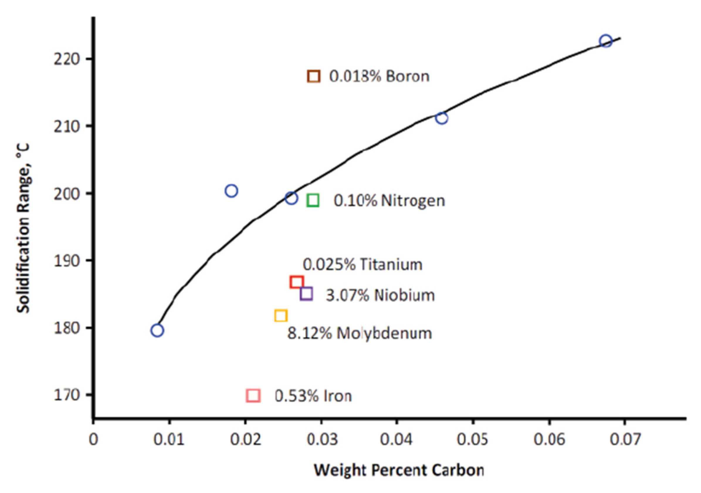
Solidification Behavior

Alloy 625 is mainly a solid-solution alloy with a face-centered cubic (FCC) structure, as shown in Figure 6 [1,11]. This structure contributes to its natural toughness [1,2]. The alloy’s composition was designed for its initial use as a replacement for Type 316 stainless steel in supercritical steam power plants [2]. The minimum nickel content, set to achieve peak stress-rupture strength at 649 °C, is about 57% [2,26]. Originally, the alloy had chromium and molybdenum contents similar to Type 316, aiming for comparable corrosion resistance [2]. However, to increase its appeal, these levels were adjusted to the current figures (as shown in Table 1), improving both tensile properties at room temperature and corrosion resistance [1,2]. Although niobium was added primarily for solid-solution strengthening, its effect on the alloy’s properties is closely linked with other elements like aluminum, titanium, and carbon, as well as the alloy’s processing [8,27].
Chromium is essential in the corrosion resistance of Alloy 625, as it forms a protective chromium oxide (Cr2O3) layer on its surface [1,3,11]. While chromium has a body-centered cubic (bcc) crystal structure, nickel has a face-centered cubic (FCC) structure [2,5]. The structural differences between these two elements are illustrated in the binary phase diagram (Figure 7a) [2,28]. This diagram clearly indicates that chromium dissolves completely in Alloy 625, confirming that it forms a solid solution.
Molybdenum is added into Alloy 625 not only to enhance corrosion resistance but also to provide atomic-level strengthening [1,2,3]. Like chromium, molybdenum has a body-centered cubic structure, distinct from nickel’s face-centered cubic configuration [29]. This distinction leads to a unique phase diagram (Figure 7b), which is significant because it demonstrates that molybdenum fully dissolves into Alloy 625, forming a solid solution (as indicated by the red area in Figure 8) [2,29].
The Figure 8 phase diagram illustrates the impact of niobium content on the development of secondary phases and grain morphology [4]. The liquidus and solidus curves define the melting behavior across varying molybdenum contents, with the eutectic reaction observed near 20.9 wt.% Mo at approximately 1820 °C [28]. The diagram indicates the stability of solid solution phases and intermetallic compounds in the Cr-rich and Mo-rich regions, relevant to Alloy 625 metallurgy for understanding solidification behavior and phase formation during welding and heat treatment [28].
Understanding Alloy 625’s behavior cannot be achieved by merely examining the Ni-Cr, Ni-Mo, and Cr-Mo systems separately. The combined effects of nickel, chromium, and molybdenum, along with other alloying elements, need to be considered [29]. This requires introducing the concept of a ternary phase diagram, which, as the name suggests, involves three components. It is a 3D diagram showing temperature and two concentration parameters as variables. Figure 9 presents a simplified version of such a diagram [30]. Binary phase diagrams are located on the three visible faces, with a third binary between elements ‘B’ and ‘C’ hidden at the back. The top surface displays contours representing alloys of constant temperature, called isotherms [30].
While Figure 9a presents a ternary phase diagram, it is not particularly helpful in its current form. To examine how the three components interact, the usual practice is to observe a cross-section of the diagram at a specific temperature. Figure 9b displays the liquidus projection for the Ni-Cr-Mo system [31], with the red shaded area highlighting the nickel, chromium, and molybdenum proportions found in Alloy 625 [32]. Figure 9b illustrates a key characteristic of the Ni-Cr-Mo system [32]. Although solidification usually starts with austenite (γ), molybdenum tends to concentrate in the remaining liquid, leading to significant molybdenum enrichment in the final liquid phase (refer to Figure 9b [32]). This encourages the formation of intermetallic compounds as solidification concludes, primarily the Laves phase, σ, and P phases (σ is more common in Alloy C-22, while P is more prevalent in Alloy C-276) [5,33,34].
The Laves phase in Alloy 625 is a hexagonal close-packed (hcp) intermetallic compound with an A2B structure (see Figure 10) [5]. In this structure, the ‘A’ atoms (red) may consist of iron, nickel, or chromium, while the ‘B’ atoms (blue) can be molybdenum, niobium, or silicon [13,16]. Named after Fritz Laves, these phases are classified based on their geometry, with ‘A’ atoms forming a diamond or hexagonal diamond pattern and ‘B’ atoms creating tetrahedra [5]. This unique configuration results in Laves phases being extremely hard and brittle at room temperature [5].
During solidification, niobium, much like molybdenum, tends to concentrate in the remaining liquid, leading to the formation of a niobium-rich Laves phase or niobium carbides as the solidification process completes. The pseudo-ternary equilibrium diagram (Figure 11) [1] helps illustrate niobium’s behavior during this stage [13,35,36]. The diagram shows that the ratio of carbon to niobium plays a critical role in determining the resulting microstructures. Depending on this ratio, the following three possible outcomes can occur:
  • High C/Nb ratio: Austenite (γ) and NbC (niobium carbide) form, without the Laves phase.
  • Intermediate C/Nb ratio: Initially forms γ and NbC, followed by the Laves phase during the final stages.
  • Low C/Nb ratio: Results in γ and Laves phase formation, without NbC.
In Alloy 625, the carbon level is usually high enough to cause both carbides and inter-metallics to form as solidification ends [1,16]. While solidification always starts with austenite, both carbon and niobium concentrate in the remaining liquid [16]. This leads to eutectic reactions forming NbC and/or the Laves phase at the final solidification stage [5,16]. The Laves phase forms instead of Ni3Nb due to the presence of other elements like Cr, Mo, Fe, and Si [5].
Excessive NbC or Laves phase in an ingot can cause problems if it is hot-worked mainly in one direction, leading to a banded microstructure with poor ductility perpendicular to the bands [5]. The Laves phase is worse in this regard than NbC, but fortunately, it can be removed by solution annealing at 1093 °C or higher [5,17]. NbC, however, is very stable and hard to eliminate; thus, proper hot working is needed to distribute it evenly [1]. Carbon content also affects the solidification range (difference between liquidus and solidus temperatures) [13,36]. Figure 12 shows how increasing the carbon significantly widens this range.
The solidification range is also influenced by other elements in the alloy. Increasing boron significantly widens this range, as it is known to lower the solidus temperature [11]. Surprisingly, raising nitrogen has little impact [11]. Reducing molybdenum, niobium, iron, and titanium to their minimum levels tends to narrow the solidification range. Cieslak also found that minimizing silicon content significantly decreases this range [13,36].
A narrower solidification range is desirable, as it reduces segregation during solidification, improving hot workability [13,36]. Therefore, reducing carbon and niobium not only limits the formation of NbC or the Laves phase but also lessens the segregation of these elements [13]. The tendency for NbC and/or the Laves phases to form during solidification restricts melt practices. The melting process and ingot size together determine the maximum heat size that will have an acceptable structure [13]. This limit is not precisely defined for Alloy 625, but for current electroslag remelting (ESR) melts, the maximum practical ingot size seems to be about 18 tons [13].

4. Welding Processes and Dilution Effects

Weld overlay cladding provides significant advantages for protecting internal equipment surfaces from corrosion and wear, offering a more effective solution than carbon steel and even solid corrosion-resistant alloys (CRA) [3,5]. It extends the life of equipment under corrosive environments by improving corrosion resistance without significantly increasing manufacturing costs [3,37].
Weld overlay cladding can be applied specifically to areas under attack, providing targeted protection where it is most needed [38]. It is versatile and can be used on complex geometrical forms, making it suitable for various industrial applications, including oil and gas, chemical processing, and marine environments. Using weld overlay cladding is a cost-effective alternative to manufacturing entire components from solid CRA [39]. It allows the use of less expensive base materials like carbon steel, with only a thin layer of expensive corrosion-resistant material applied on top. This approach significantly reduces the overall manufacturing costs while still providing excellent corrosion resistance [40].
The selection of welding parameters, including arc voltage, hot wire current, welding speed, and wire feed rate, has a significant impact on the dilution and thickness of the overlay layer. Optimizing these parameters is essential to enhance both productivity and weld quality [3,13,40].
The base metal dilution caused by the weld overlay, which is influenced by the above parameters, has significant consequences on the weld overlay properties, including corrosion resistance [13].
Various welding processes such as Gas Tungsten Arc Welding (GTAW), also known as Tungsten Inert Gas (TIG) welding, Gas Metal Arc Welding (GMAW), commonly referred to as Metal Inert Gas (MIG) welding, Submerged Arc Welding (SAW), and Flux-Cored Arc Welding (FCAW) are applied based on the size, geometry, and metallurgical requirements of the components [41,42].
  • GTAW (TIG) uses a non-consumable tungsten electrode and an inert gas shield (typically argon) to produce high-quality, precise welds, especially suited for thin sections of stainless steel and non-ferrous metals [43].
  • GMAW (MIG) employs a continuously fed consumable wire electrode and a shielding gas, offering high productivity and ease of automation [44].
  • SAW involves the formation of an arc between a continuously fed electrode and the workpiece, with the arc submerged under a blanket of granular flux that prevents spatter and sparks, making it ideal for thick materials and long welds [33,34].
  • FCAW is a semi-automatic or automatic process that uses a tubular wire filled with flux, which may or may not require an external shielding gas, offering good penetration and high deposition rates, even in outdoor or windy conditions [45].
While weld overlay cladding provides enhanced corrosion and wear resistance, it is important to consider potential challenges, such as the reduction in fatigue life of specimens. This highlights the need for understanding how different welding processes affect the mechanical and metallurgical properties of the overlay and substrate material [45].

4.1. Mechanical Benefits [46,47]

  • Weld overlay cladding can enhance mechanical properties, including high strength and wear resistance.
  • It has been found that weld overlay can produce better adhesion between the substrate and clads to enhance mechanical and tribological characteristics.
  • The use of weld overlay on medium-strength low alloy steel has been shown to improve both the strength and corrosion resistance.

4.2. Corrosion Resistance Benefits [45]

  • Weld overlay offers clear advantages in areas of wear and corrosion protection for pipeline systems and oil and gas equipment.
  • Nickel-based weld overlays are commonly used in the oil and gas industry while preserving the based metal strength, toughness, and compatibility with the external medium, including cathodic protection to improve corrosion resistance without significantly increasing manufacturing costs.
  • Cladding with corrosion-resistant alloys provides compact and tightly bonded layers on less expensive materials, offering protection against corrosion in various industries such as oil and gas, chemical, and energy.
  • The use of weld overlay has been widely employed to protect components from wear and corrosion, providing good resistance to general corrosion in coal-fired power plants.

4.3. Economic Benefits [37]

  • Weld overlay is a recognized cost-saving technology that offers practical and financial benefits by increasing the life expectancy of marine equipment and components, both offshore and onshore, in the oil and gas industry.
  • Weld cladding offers a cost-effective solution for achieving corrosion resistance in various industrial applications. By significantly reducing the cost of materials and improving the durability of components, it provides a practical alternative to using solid alloys.
  • The technology of weld overlay provides a heavy-duty metallurgically bonded protective layer, avoiding the need to produce entire components from expensive corrosion-resistant materials, thus resulting in cost savings.

4.4. Environmental Benefits [48]

  • Weld overlay cladding can be used to protect equipment in aggressive environments, such as those exposed to acids and chlorides, thereby reducing the impact of erosion due to sand and extending the service life of the equipment.
  • The use of weld overlay cladding in petroleum refinery processing has been shown to provide protection against sulfidation attack, contributing to the reduction of high-temperature corrosion issues in the industry.

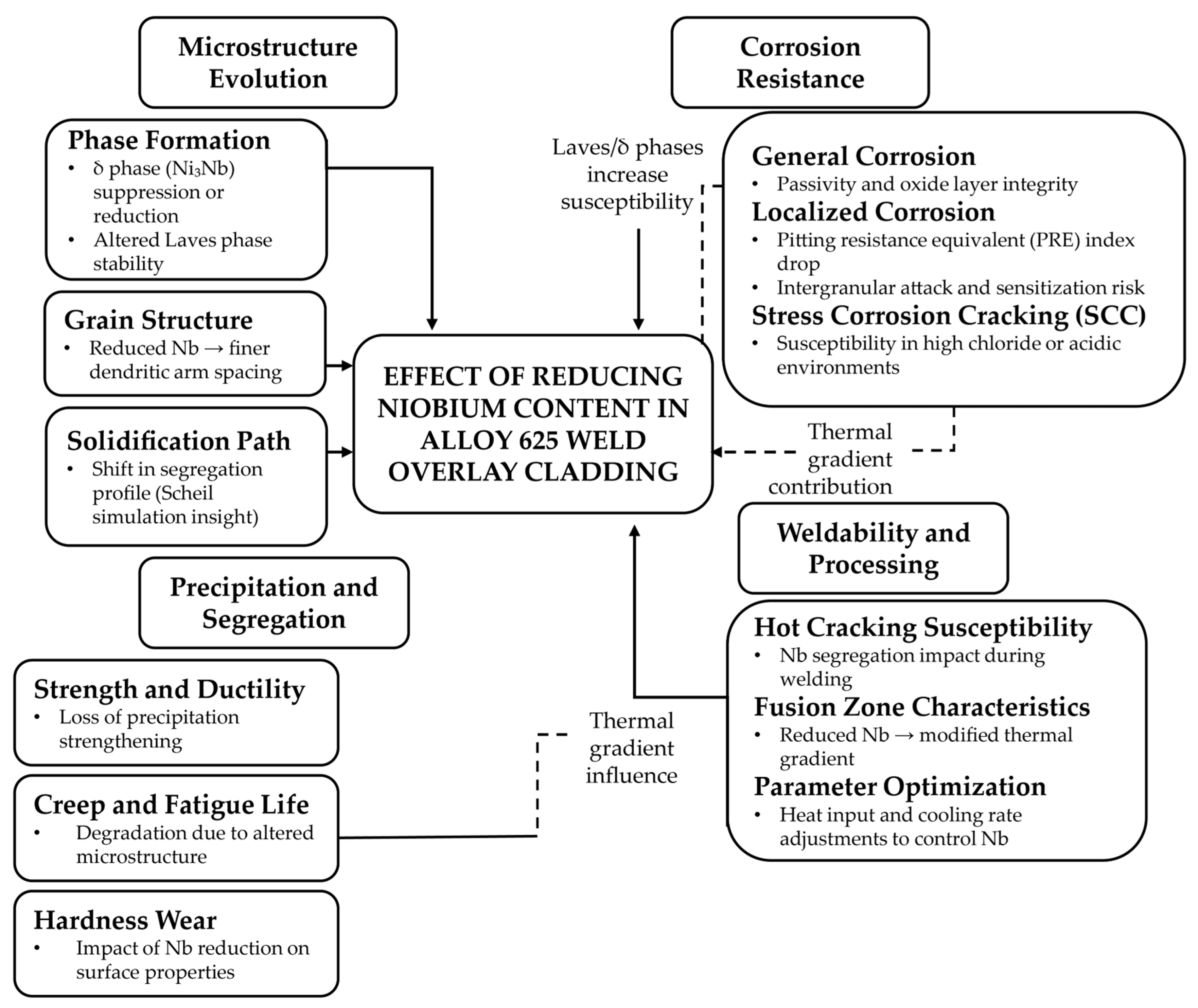
5. Effect of Niobium Reduction on Alloy 625 Cladding

As introduced in Section 1, Alloy 625 is a niobium-enriched nickel-based superalloy that is extensively used for its outstanding corrosion resistance and mechanical strength in demanding environments. When applied as a weld overlay, it serves as a protective barrier, safeguarding underlying components from corrosive and erosive damage in industries such as chemical processing, marine operations, and oil and gas [46]. Weld overlay cladding acts as a defensive barrier, shielding the base material from corrosive and erosive damage [3]. However, high niobium content, while beneficial for strength, is associated with the formation of detrimental phases such as the Laves phase and niobium carbides during welding processes [5,11,49]. These phases can compromise the mechanical integrity and long-term performance of the cladding [13].
To mitigate these effects, researchers and engineers have explored strategies to reduce the Nb content in Alloy 625 weld overlays [13,33]. Adjusting the alloy composition aims to suppress the formation of brittle phases, improve weldability, and enhance the overall performance of the cladding system [13]. This review evaluates the impact of niobium reduction on the microstructure, mechanical properties, corrosion resistance, weldability, and processability of Alloy 625 cladding.
The conceptual framework in Figure 13 illustrates the effects of reducing niobium (Nb) content in Alloy 625 weld overlay cladding. The diagram highlights how Nb reduction influences microstructure evolution, precipitation behavior, mechanical properties, corrosion resistance, and weldability. It emphasizes the systematic interrelationships such as the role of phase segregation in increasing cracking and corrosion susceptibility based on insights from solidification modeling, precipitation kinetics, and processing property performance relationships.

5.1. Microstructure of Alloy 625 Weld Overlay Cladding

The microstructure of Alloy 625 weld overlay cladding predominantly consists of a face-centered cubic (FCC) austenitic matrix, strengthened by various secondary phases [1]. Niobium is a potent element that strongly influences phase formation and distribution [5,7]. At elevated Nb concentrations, the alloy is prone to the precipitation of Nb-rich phases, including Laves phases (Fe2Nb or Ni2Nb) and carbides such as NbC and M6C, particularly during solidification and cooling [13,16,17]. These phases are inherently brittle and promote localized stress concentrations, which are detrimental to the mechanical performance of the cladding [7].
The reduction of niobium content effectively lowers the volume fraction of these undesirable phases [13,16,18]. With less Nb available for precipitation reactions, the alloy’s microstructure becomes finer and more homogeneous [5,7]. This refined microstructure contributes to enhanced mechanical properties and improves the overall reliability of the cladding under service conditions [5,7].

5.2. Mechanical Properties of Alloy 625 Weld Overlay

The mechanical performance of Alloy 625 weld overlays is closely tied to its microstructural characteristics [1,5,7]. High niobium content enhances strength and hardness by promoting solid solution strengthening and secondary phase precipitation [13,16]. However, the trade-off is reduced ductility and increased brittleness due to the excessive formation of Laves phases and carbides [5,7].
Lowering the niobium content results in a slight decrease in hardness and tensile strength but significantly improves ductility and toughness [5]. The reduction of brittle phase formation allows the material to accommodate greater plastic deformation before fracture, enhancing its overall mechanical reliability [5]. These improvements are particularly valuable in demanding applications where high fracture toughness and resistance to crack propagation are essential [18].

5.3. Corrosion Resistance of Alloy 625 Weld Overlay

The corrosion resistance of Alloy 625 weld overlay cladding is primarily attributed to the formation of a passive oxide layer on its surface [3]. This layer acts as a barrier, protecting the underlying material from corrosive attack. Nb contributes to the formation and stability of this passive layer by forming Nb oxides [7,52]. However, excessive Nb content can lead to the formation of Nb-rich precipitates, which disrupt the passive layer and compromise corrosion resistance [52].
Reducing the Nb content may slightly decrease the initial corrosion resistance of the cladding due to reduced Nb oxide formation, but it also mitigates the risk of passive layer disruption caused by precipitates, leading to improved long-term corrosion performance [48,53].

5.4. Weldability

Weldability is a critical consideration in Alloy 625 cladding applications [54]. High niobium content increases the alloy’s susceptibility to solidification cracking and weld defects, primarily due to the formation of brittle intermetallic phases in the fusion zone [26,48,54]. By reducing the Nb content, weldability improves significantly [55]. Lower Nb levels promote greater homogeneity in the weld pool, decrease cracking tendencies, and enable more efficient deposition rates with fewer welding defects [27,50]. These improvements contribute to more reliable fabrication and reduced post-weld corrective procedures [54].

5.5. Processability and Performance Summary

A summary of the comparative effects of high and reduced niobium content on Alloy 625 cladding is presented in Table 2. The table highlights the trade-offs and benefits associated with adjusting niobium levels, providing a clear reference for material selection and process optimization.

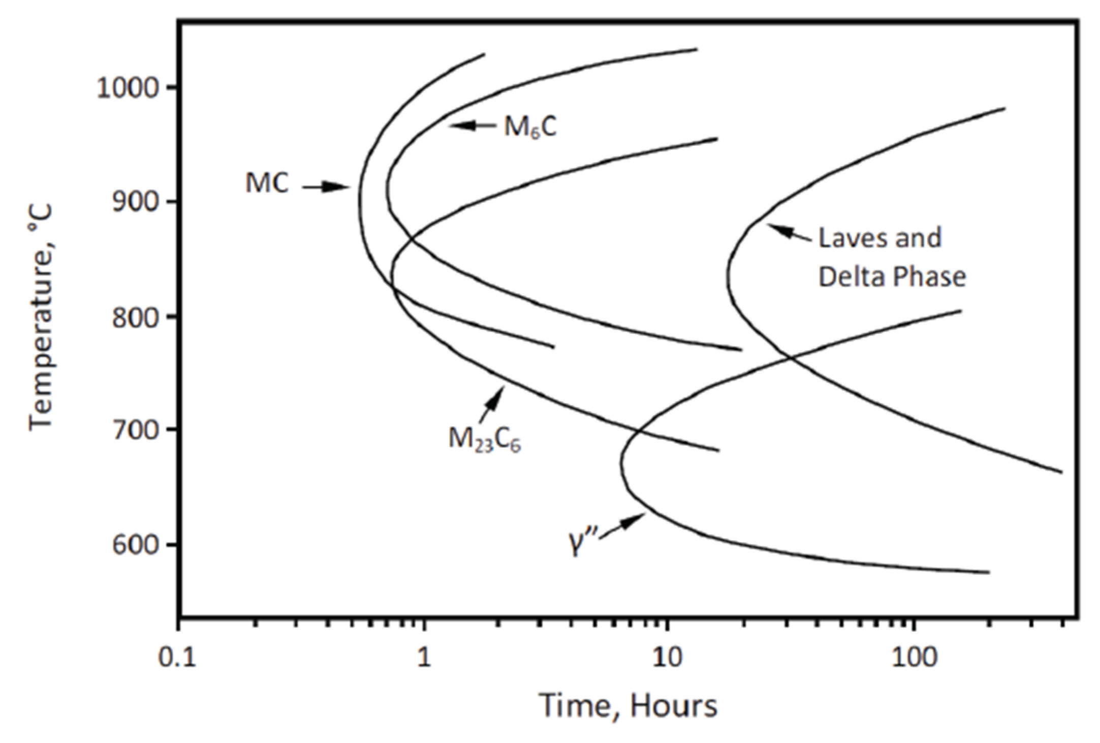
6. Phase Transformations and Nb Influence

The discussion of phase transformations in Alloy 625 assumes that the starting material has been subjected to solution annealing. As a result, all phases, except for the primary niobium carbide (NbC) particles, are dissolved into the solid solution [1,16].
The time-temperature-transformation (TTT) diagram is used to illustrate potential phase transformations in Alloy 625 [16]. While several TTT diagrams exist for this alloy with minor variations, this article uses the version shown in Figure 14, which represents typical heats of wrought Alloy 625, with compositions falling within the specified range of Table 1 [5].
The key feature of Figure 14 is the γ” curve. When sufficient amounts of niobium, titanium, and aluminum are present, γ” precipitates as fine Ni3(Nb + Ti + Al) particles in the temperature range from 590 to 760 °C [5]. The γ” phase has a body-centered tetragonal (BCT) crystal structure, where nickel and niobium atoms are arranged in an ordered manner 625 matrix. This mismatch induces strain, which, along with order hardening, contributes to the strengthening effect of γ” (Figure 15) [5]. These disc-shaped γ” precipitates form due to the structural mismatch between their BCT configuration and the face-centered cubic (FCC) structure of the alloy.
Additionally, as shown in Figure 15, various carbides and intermetallic phases can precipitate in Alloy 625 after exposure to heat for periods ranging from approximately 0.1 to 100 h [5].

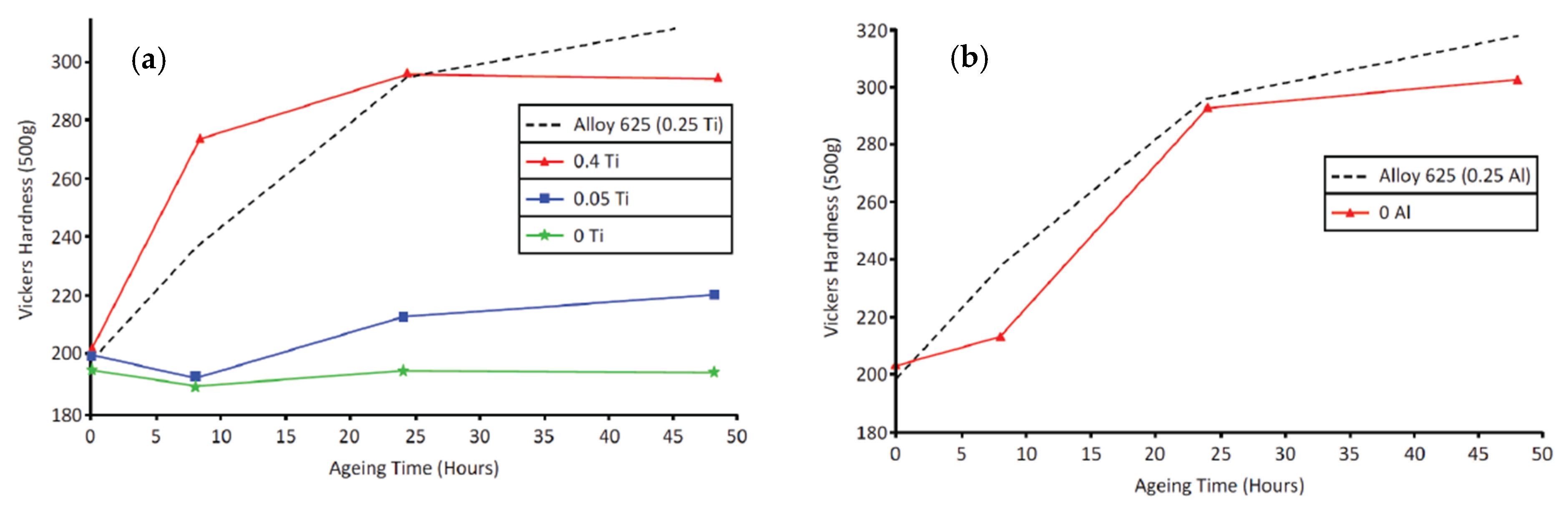
6.1. γ” Precipitation

Alloy 625 was not initially developed as a precipitation-hardened alloy [2]. However, the precipitation of γ” is significantly influenced by the concentrations of niobium, titanium, and aluminum [5]. Even slight variations in these elements can greatly affect the likelihood of γ” precipitating [5,7]. The effect of titanium content is illustrated in Figure 16a, based on data from samples with consistent compositions and approximately 3.85% niobium [1]. The figure shows that reducing titanium levels from 0.4% to 0.05%, and eventually to zero, significantly delays the formation of γ” [1]. Figure 16b highlights that removing aluminum has a much smaller impact on precipitation compared to titanium [1]. Microstructural analysis confirmed that γ” was solely responsible for precipitation hardening in these experiments, with no γ’ or other hardening phases identified [56]. Similar chemical effects were observed in studies by Guo et al. [56].
Based on the data from Figure 16a,b, researchers suggested that the unique effects of niobium, titanium, and aluminum could be due to the formation of a Ni3(Nb + Ti + Al) γ” precipitate [56].
In addition to composition changes, processing history can influence γ” precipitation morphology [5,7]. If particles like NbC, Laves, or Delta phases are present near grain boundaries, then the surrounding areas may become niobium-depleted, slowing γ” formation and creating γ”-depleted zones [5,7]. While such zones are often associated with decreased mechanical performance or corrosion resistance in other alloys [5], limited information is available regarding their specific effects in Alloy 625 [5,7].

6.2. Carbides

As shown in Figure 14, three different carbides can form in wrought Alloy 625 and exist as grain boundary precipitates [5]. Although the exact positions of the carbide curves’ noses are not well defined, they occur around 10 min, suggesting that, even in large Alloy 625 components, grain boundary carbides will not form after air cooling from solution annealing, especially when accelerated cooling like water quenching is applied [5].
The type of carbide that forms is temperature-dependent [5]. At higher temperatures (870 to 1038 °C), NbC (as thin grain boundary films) and MC (where M represents Ni, Cr, and Mo) are the primary carbides [7]. In the range from 705 to 915 °C, M23C6 (primarily Cr-rich) carbides are more prevalent [5]. After intermediate heat treatments around 870 °C, all three carbides—M6C, NbC, and M23C6—are typically present [5].
The precipitation of grain boundary carbides is influenced by the silicon and carbon content [13,16]. When carbon exceeds 0.035%, silicon has a minimal effect, but at lower carbon levels, carbide formation slows significantly if silicon is below 0.15% [5,7]. Although the precise mechanism remains unclear, M6C carbides in Alloy 625 typically contain about 5% silicon by weight [5], suggesting that silicon may promote M6C formation [5,7].
Grain boundary carbides negatively affect corrosion resistance and mechanical properties by reducing ductility and toughness [5,7]. Fortunately, carbides can be dissolved through solution annealing at 1093 °C or higher, typically requiring only an hour at that temperature [1,5].

6.3. Intermetallics

As shown in Figure 14, the precipitation of both Laves and Delta phases occurs as exposure time increases [13]. This process begins at grain boundaries where carbides are already present. Laves particles exhibit a morphology that closely resembles the blocky, irregular shapes of M6C and M23C6 carbides. The Delta phase, on the other hand, features an orthorhombic D0a structure, as illustrated in Figure 17, with acicular-shaped particles [5,7]. While Laves and Delta phase precipitation is displayed as a single curve in Figure 14, this may not be entirely accurate in all instances. Both phases rely on niobium diffusion for their formation, meaning the precipitation kinetics for the two are likely to be quite similar.
At lower temperatures along the curve, the Delta phase precipitates at grain boundaries as well as at coherent and incoherent twin boundaries. As the temperature increases, the Delta phase precipitation progresses within the grains themselves (intragranular).
The Delta phase can also form when γ” becomes unstable at temperatures above approximately 650 °C [11]. Although Delta phase precipitates are incoherent and tend to reduce the strength of alloys typically reinforced by γ”, their controlled formation can provide benefits such as grain stabilization [11].
While the impact of Laves and Delta phases is less severe than that of M6C and M23C6 carbides, their presence still reduces the ductility and toughness of the material. Both Laves and Delta phases can be dissolved back into the solution through annealing at 1093 °C, but this process requires considerably longer annealing times than those needed to dissolve carbides [11].

7. Compositional Modification

The processing history and chemical composition of individual heats of Alloy 625 can greatly affect the resulting structures and properties of each heat [1,2,5]. Variations in both processing and composition can lead to significant differences in the material’s characteristics [1,2,5]. For critical applications, where consistency across heats is essential, it may be necessary to impose stricter compositional limits than those outlined in Table 3 [1,5]. Achieving this requires a careful evaluation of the trade-offs that may arise from altering the composition.
Laves and NbC particles, which form during solidification, along with Laves and Delta phase particles generated during heat treatment, can negatively affect the material and should be minimized [5,17]. Although grain boundary carbides are generally viewed as harmful, certain types and distributions can enhance stress corrosion resistance in specific conditions [17]. Moreover, when high strength is required, the presence of γ” precipitates becomes essential [5,7,17].
The first consideration is whether grain boundary carbides or γ” precipitation hardening are necessary for the intended application. Following this, the impact of different alloying elements on key material properties should be carefully evaluated. Table 4 provides an overview of how altering the alloy’s composition can influence mechanical properties, corrosion resistance, and weldability. It is crucial to understand that, for specific applications, the effects of compositional changes must be thoroughly assessed, and the table may not fully capture the nuances of all scenarios. The essential point is that optimizing the alloy’s composition requires considering all potential consequences to ensure that solving one issue does not inadvertently create another [5,7,17].
Another essential factor to consider is the cost. The imposition of too-stringent chemistry ranges can incur significant costs and should be avoided if not essential [1,5].

8. Discussion

The authors’ previous work explored the application of weld overlay cladding using a directed energy deposition technique to enhance the corrosion resistance of materials used in geothermal power systems in the Philippines [57]. That study emphasized the critical role of material selection in geothermal wells, where harsh operating conditions can lead to early component degradation. The research provided an overview of corrosion challenges specific to geothermal environments, discussed the key factors influencing material selection, and outlined an approach to systematically assess candidate materials. It also emphasized the importance of balancing material properties, environmental conditions, and cost.
While reducing niobium (Nb) content in Alloy 625 shows promise in reducing the formation of undesirable phases, its influence on other essential properties, such as high-temperature strength and corrosion resistance, requires further investigation.
The next phase of this research will focus on studying the effects of controlled Nb reduction in commercial-grade Alloy 625, specifically when applied as a weld overlay on carbon–manganese steel using the Automatic Hot Wire TIG cladding method. Thermodynamic simulations using the CALPHAD approach have already been conducted in this study to predict phase equilibria, considering dilution levels from 0% to 100%.
These initial findings provide a foundation for the continued evaluation of Alloy 625’s behavior in weld overlay applications, with particular interest in its suitability for additive manufacturing processes and use in demanding service environments.
Future work will further examine the relationship between alloy composition and the resulting corrosion, chemical, and mechanical properties after weld overlay cladding. This includes detailed microstructural and phase analyses of the modified Alloy 625 cladding layer, using advanced techniques such as analytical electron microscopy and microhardness profiling.
The outcomes of this research are expected to support the weld overlay cladding industry by helping to define the optimal properties of corrosion-resistant alloys (CRAs) for use in highly corrosive operating conditions. The findings will contribute to more informed material selection and process optimization in the development of durable cladding solutions for demanding service environments.

9. Conclusions

Reducing the niobium (Nb) content in Alloy 625 weld overlays has significant implications for the microstructure, corrosion behavior, weldability, and mechanical performance of the material. Lowering Nb content affects the formation of secondary phases such as NbC and Laves phases. These phases are typically observed in higher Nb content alloys and contribute to the overall microstructure [51]. A reduction in Nb can lead to a more uniform microstructure with fewer segregations, which can be beneficial for mechanical properties and corrosion resistance [51,58].
Nb plays a relevant role in stabilizing the alloy against intergranular attack and enhancing its passivation capacity. Reducing the Nb content may potentially decrease the corrosion resistance of the alloy, especially in chloride-containing environments [59]. However, the formation of NbC can consume carbon, releasing more chromium into the matrix, which can improve passivation and corrosion resistance in some cases [51]. Studies have shown that weld overlays with a lower Nb content exhibit reduced pitting resistance and a smaller passive region, indicating a higher susceptibility to localized corrosion [51,60].
Nb segregation during welding can lead to the formation of brittle phases, which can affect the weldability and mechanical integrity of the weld overlays [61]. Reducing Nb content can minimize the formation of these brittle phases, potentially improving the weldability and reducing the risk of hydrogen-assisted cracking (HAC) [62].
The presence of Nb-rich phases such as NbC and Laves phases can enhance the hardness and strength of the alloy. However, excessive Nb content can lead to embrittlement and reduced ductility [60,61,62]. Lower Nb content can result in a more ductile microstructure with improved toughness, although it may slightly reduce the overall hardness and strength [51,61].
A key mechanism for improving the microstructure of Alloy 625 weld overlays involves minimizing the formation of brittle niobium-rich intermetallic and carbides during solidification. This approach promotes a more uniform microstructure and reduces crack-prone zones, thereby enhancing weldability. Small additions of Nb can refine the microstructure and improve mechanical properties, but excessive segregation during welding leads to phase instability and embrittlement [49].
Solution heat treatment can dissolve Nb-rich Laves phases and reduce voids, enhancing corrosion resistance and wear properties, when practical. Aging heat treatment can lead to the formation of grain boundary carbides, which may affect mechanical properties.
Nb stabilizes alloys against intergranular attack and contributes to resistance in various environments, including high-temperature and chloride-rich conditions. However, the excessive depletion of Nb can reduce the formation of protective scales and increase susceptibility to localized corrosion [55].
Maintaining an appropriate Nb content is necessary for balancing mechanical properties and corrosion resistance. Excessive Nb can lead to the formation of brittle inter-metallics, while insufficient Nb can compromise corrosion resistance. Thermo-mechanical processing and heat treatments can optimize the microstructure, enhancing corrosion resistance and mechanical properties by controlling the distribution and size of Nb-rich phases [62,63].
From a design and application standpoint, achieving a carefully balanced alloy composition is essential for maintaining both structural and chemical stability during fabrication and service. Nb content is relevant for stabilizing alloys against intergranular attack and enhancing resistance to stress corrosion cracking [49].
Future research should focus on the experimental validation of these findings using systematic corrosion and mechanical testing under realistic service conditions. Advanced modeling approaches, including CALPHAD-based thermodynamic simulations and phase-field analysis, are recommended to further explore phase transformations and guide composition–process–property optimization.
There is a need for the experimental validation of current findings through systematic corrosion and mechanical testing. These tests should be conducted under realistic service conditions to ensure that the results are applicable to real-world scenarios. This approach will help confirm the effectiveness of alloy compositions and processing methods in practical applications. Utilizing CALPHAD (Calculation of Phase Diagrams) methods can provide valuable insights into the thermodynamic behavior of alloy systems. These simulations can help predict phase stability and transformations, which are critical for understanding how different compositions will perform under various conditions. Implementing phase field modeling can further explore the dynamics of phase transformations during processing and service. This technique allows for the detailed examination of microstructural evolution, which is essential for optimizing alloy properties.
The combination of experimental validation and advanced modeling approaches will facilitate a more comprehensive understanding of the relationships between composition, processing conditions, and resulting material properties. This knowledge is necessary for guiding the optimization of alloys to achieve desired performance characteristics.

Author Contributions

Conceptualization, R.G.T., T.B.K. and R.C.d.M.; methodology, R.G.T. and T.B.K.; software, R.G.T.; validation, R.G.T. and T.B.K.; formal analysis, R.G.T.; investigation, R.G.T.; re-sources, R.G.T.; data curation, R.G.T.; writing—original draft preparation, R.G.T.; writing—review and editing, R.G.T., T.B.K. and R.C.d.M.; visualization, R.G.T.; supervision, R.G.T., T.B.K., R.C.d.M., M.C.E.M. and J.P.H.; project administration, R.G.T. All authors have read and agreed to the published version of the manuscript.

Funding

This research received no external funding.

Acknowledgments

The authors acknowledge the technological collaboration provided by the Cladtek Group in Batam, Indonesia, and Villares Metal in Brazil in facilitating this research.

Conflicts of Interest

Author Tiago Bohn Kaspary was employed by the company Cladtek do Brasil. Author Raimundo Cabral de Medeiros was employed by the company Consórcio Ocyan & Mota-Engil Malha de Gas. The remaining authors declare that the research was conducted in the absence of any commercial or financial relationships that could be construed as a potential conflict of interest.

References

  1. Floreen, S.; Fuchs, G.; Yang, W. The Metallurgy of Alloy 625. In Superalloys 718, 625, 706 and Various Derivatives; Loria, E.A., Ed.; The Minerals, Metals & Materials Society: Pittsburgh, PA, USA, 1994. [Google Scholar] [CrossRef]
  2. Eiselstein, H.; Tillack, D. The Invention and Definition of Alloy 625. In Superalloys 718, 625 and Various Derivatives; Loria, E.A., Ed.; The Minerals, Metals & Materials Society: Pittsburgh, PA, USA, 1991. [Google Scholar] [CrossRef]
  3. NACE MR0175/ISO 15156; Petroleum and Natural Gas Industries—Materials for Use in H2S-Containing Environments in Oil and Gas Production. NACE International: Houston, TX, USA, 2024; p. 24.
  4. Eiselstein, H.L. Metallurgy of a columbium-hardened nickel-chromium-iron alloy. In Advances in the Technology of Stainless Steels and Related Alloys; ASTM: West Conshohocken, PA, USA, 1965; pp. 62–79. [Google Scholar] [CrossRef]
  5. DuPont, J.N.; Lippold, J.C.; Kiser, S.D. Welding Metallurgy and Weldability of Nickel-Base Alloys; Wiley: Hoboken, NJ, USA, 2009. [Google Scholar] [CrossRef]
  6. Bowman, R. Superalloys: A primer and history. In Proceedings of the 9th International Symposium on Superalloys, Warrendale, PA, USA, 17–21 September 2000; p. 6. [Google Scholar]
  7. Dupont, J.N.; Robino, C.V.; Marder, A.R. Solidification and weldability of Nb-bearing superalloys. Weld. J. 1998, 77, 417–431. [Google Scholar]
  8. Kumara, C.; Balachandramurthi, A.R.; Goel, S.; Hanning, F.; Moverare, J. Toward a better understanding of phase transformations in additive manufacturing of Alloy 718. Materialia 2020, 13, 100862. [Google Scholar] [CrossRef]
  9. DeArdo, A.J. Niobium in modern steels. Int. Mater. Rev. 2003, 48, 371–402. [Google Scholar] [CrossRef]
  10. Pasiowiec, H.; Dubiel, B.; Dziurka, R.; Bała, P.; Ledwig, P.; Wróbel, M.; Gajewska, M.; Ziaja, W.; Poręba, M. Effect of creep deformation on the microstructure evolution of Inconel 625 nickel-based superalloy additively manufactured by laser powder bed fusion. Mater. Sci. Eng. A 2023, 887, 145742. [Google Scholar] [CrossRef]
  11. Singh, J.B. (Ed.) Physical Metallurgy of Alloy 625. In Alloy 625: Microstructure, Properties and Performance; Chapter 3; Springer Nature: Singapore, 2022; pp. 67–110. [Google Scholar] [CrossRef]
  12. American Welding Society (AWS). AWS A5.14: Specification for Nickel and Nickel-Alloy Bare Welding Electrodes and Rods; AWS: Miami, FL, USA, 2024. [Google Scholar]
  13. Silva, C.C.; de Miranda, H.C.; Motta, M.F.; Farias, J.P.; Afonso, C.R.M.; Ramirez, A.J. New insight on the solidification path of an alloy 625 weld overlay. J. Mater. Res. Technol. 2013, 2, 228–237. [Google Scholar] [CrossRef]
  14. Zhao, S.; Xie, X.; Smith, G.D.; Patel, S.J. Microstructural stability and mechanical properties of a new nickel-based superalloy. Mater. Sci. Eng. A 2003, 355, 96–105. [Google Scholar] [CrossRef]
  15. Belan, J.; Kuchariková, L.; Vaško, A.; Tillová, E.; Chalupová, M.; Matvija, M. The SEM and TEM Analysis of IN718 Alloy after Fatigue Push-Pull Loading at 700 °C. Defect Diffus. Forum 2020, 405, 288–293. [Google Scholar] [CrossRef]
  16. Petrzak, P.; Kowalski, K.; Blicharski, M. Analysis of Phase Transformations in Inconel 625 Alloy during Annealing. Acta Phys. Pol. A 2016, 130, 1041–1044. [Google Scholar] [CrossRef]
  17. Lippold, J.C. Welding Metallurgy and Weldability; John Wiley & Sons: Hoboken, NJ, USA, 2014. [Google Scholar]
  18. Bunaziv, I.; Olden, V.; Akselsen, O.M. Metallurgical Aspects in the Welding of Clad Pipelines—A Global Outlook. Appl. Sci. 2019, 9, 3118. [Google Scholar] [CrossRef]
  19. Silva, C.C.; de Albuquerque, V.H.C.; Miná, E.M.; Moura, E.P.; Tavares, J.M.R.S. Mechanical Properties and Microstructural Characterization of Aged Nickel-based Alloy 625 Weld Metal. Met. Mater. Trans. A 2018, 49, 1653–1673. [Google Scholar] [CrossRef]
  20. Maltin, C.A.; Galloway, A.M.; Mweemba, M. Microstructural Evolution of Inconel 625 and Inconel 686CPT Weld Metal for Clad Carbon Steel Linepipe Joints: A Comparator Study. Met. Mater. Trans. A 2014, 45, 3519–3532. [Google Scholar] [CrossRef]
  21. Gibson, C.; Kelebek, S.; Aghamirian, M. Niobium oxide mineral flotation: A review of relevant literature and the current state of industrial operations. Int. J. Miner. Process. 2015, 137, 82–97. [Google Scholar] [CrossRef]
  22. Bayraktar, E.; Gatamorta, F.; Enginsoy, H.M.; Polis, J.E.; Miskioglu, I. New Design of Composites from Fresh Scraps of Niobium for Tribological Applications. In Mechanics of Composite, Hybrid and Multifunctional Materials: Conference Proceedings of the Society for Experimental Mechanics Series; Springer: Cham, Switzerland, 2021; pp. 35–43. [Google Scholar] [CrossRef]
  23. Kirkwood, P. Welding Niobium Bearing HSLA Steels “Myths and Magic”. In HSLA Steels 2015, Microalloying 2015 & Offshore Engineering Steels 2015: Conference Proceedings; John Wiley & Sons, Inc.: Hoboken, NJ, USA, 2015. [Google Scholar] [CrossRef]
  24. Procario, J.R.; Melfi, T. Submerged arc welding solutions for niobium micro-alloyed pipe steel—Weld metal alloy systems. In Proceedings of the Rio Pipeline Conference & Exposition 2011, Rio de Janeiro, Brazil, 20–22 September 2011. Technical Papers. [Google Scholar]
  25. Almatani, R.A.; DeArdo, A.J. Rational Alloy Design of Niobium-Bearing HSLA Steels. Metals 2020, 10, 413. [Google Scholar] [CrossRef]
  26. Hariharan, K.; Iams, A.D.; Zuback, J.S.; Palmer, T.A.; Sridhar, N.; Alazemi, R.M.; Frankel, G.S.; Schindelholz, E.J. Enhanced localized corrosion resistance of Ni-based alloy 625 processed by directed energy deposition additive manufacturing. Corros. Sci. 2024, 230, 111945. [Google Scholar] [CrossRef]
  27. Khaple, S.; Prakash, U.; Golla, B.R.; Prasad, V.V.S. Effect of Niobium Addition on Microstructure and Mechanical Properties of Fe–7Al–0.35C Low-Density Steel. Met. Microstruct. Anal. 2020, 9, 127–139. [Google Scholar] [CrossRef]
  28. Hojerslev, C.; Tiedje, N.; Hald, J. Segregation Effects and Phase Developments during Solidification of Alloy 625. Mater. Sci. Forum 2006, 508, 373–378. [Google Scholar] [CrossRef]
  29. Yamamoto, K.; Kimura, Y.; Mishima, Y. Effect of Matrix Substructures on Precipitation of the Laves Phase in Fe-Cr-Nb-Ni System. ISIJ Int. 2003, 43, 1253–1259. [Google Scholar] [CrossRef]
  30. Baker, H. (Ed.) Alloy Phase Diagrams, 10th ed.; ASM Handbook; ASM International: Novelty, OH, USA, 1992; Volume 3. [Google Scholar]
  31. Nash, P. Ni-Cr System; ASM International: Novelty, OH, USA, 1991. [Google Scholar]
  32. Singleton, M.F.; Nash, P. Ni-Mo System; ASM International: Novelty, OH, USA, 1991. [Google Scholar]
  33. DuPont, J.N. Solidification of an alloy 625 weld overlay. Met. Mater. Trans. A 1996, 27, 3612–3620. [Google Scholar] [CrossRef]
  34. DuPont, J.N.; Babu, S.; Liu, S. Welding of materials for energy applications. Metall. Mater. Trans. A 2013, 44, 3385–3410. [Google Scholar] [CrossRef]
  35. Ogborn, J.S.; Olson, D.L.; Cieslak, M.J. Influence of solidification on the microstructural evolution of nickel base weld metal. Mater. Sci. Eng. A 1995, 203, 134–139. [Google Scholar] [CrossRef]
  36. Perricone, M.J.; DuPont, J.N.; Cieslak, M.J. Solidification of hastelloy alloys: An alternative interpretation. Met. Mater. Trans. A 2003, 34, 1127–1132. [Google Scholar] [CrossRef]
  37. Farkade, N.V.; Ravanan, P.M. Modification in Weld Overlay for Productivity and Corrosion Resistance. Int. J. Sci. Technol. Eng. 2015, 2, 37–41. Available online: https://www.semanticscholar.org/paper/5b2743a78674ec6b4f57319dfa50641e6dee3520 (accessed on 28 April 2025).
  38. Reda, A.; Noor, M.Z.Z.; Karrech, A. CRA Clad Pipes: Do Their Benefits Justify Sole Selection? J. Pipeline Sci. Eng. 2024, 100245. [Google Scholar] [CrossRef]
  39. Reda, A.; Kaspary, T.; Chimbli, S.; Montague, P.; Goodier, S.; Shahin, M.A. Material Review of Geothermal Resources Extracted from Deep Pilot Wells in the Salton Sea. In Proceedings of the AMPP Annual Conference + Expo 2025, Nashville, TN, USA, 6–10 April 2025. [Google Scholar] [CrossRef]
  40. Reda, A.; Shahin, M.A.; Montague, P. Review of Material Selection for Corrosion-Resistant Alloy Pipelines. Eng. Sci. 2025, 33, 1373. [Google Scholar] [CrossRef]
  41. Badisch, E.; Roy, M. Hardfacing for wear, erosion and abrasion. In Surface Engineering for Enhanced Performance Against Wear; Springer: Vienna, Austria, 2013. [Google Scholar] [CrossRef]
  42. Brown, A. Increasing the life expectancy of marine equipment. Mar. Eng. Rev. 2007, 32–33. [Google Scholar]
  43. Zhang, Y.M.; Lu, W.; Liu, Y.C. Guided Arc Enhances GTAW. Weld. J. 2003, 82, 40–45. [Google Scholar]
  44. Rajkumar, V.; Arjunan, T.V.; Kannan, A.R. Metallurgical and mechanical investigations of Inconel 625 overlay welds produced by GMAW-hardfacing process on AISI 347 pipes. Mater. Res. Express 2019, 6, 076534. [Google Scholar] [CrossRef]
  45. Alvarães, C.P.; Madalena, F.C.A.; de Souza, L.F.G.; Jorge, J.C.F.; Araújo, L.S.; Mendes, M.C. Performance of the INCONEL 625 alloy weld overlay obtained by FCAW process. Matéria 2019, 24, e12290. [Google Scholar] [CrossRef]
  46. Mohammed, R.; Kumar, E.N.; Ram, G.J.; Kamaraj, M.; Reddy, G.M.; Rao, K.S. Microstructure, Mechanical and Corrosion Behaviour of Weld Overlay Cladding of DMR 249A steel with AISI 308L. Mater. Today Proc. 2019, 15, 2–10. [Google Scholar] [CrossRef]
  47. Wang, Z.L.; Ding, X. Mechanical Property and Corrosion Resistance of the E309L Buffer Layer in Weld Overlay. Appl. Mech. Mater. 2014, 668–669, 39–42. [Google Scholar] [CrossRef]
  48. Kumar, R.; Bose, S. Influence of process parameters on mechanical properties in weld cladding. In Recent Advancements in Computational Intelligence and Design Engineering; CRC Press: Boca Raton, FL, USA, 2024; pp. 399–402. [Google Scholar] [CrossRef]
  49. Singh, J. Corrosion Behavior of Alloy 625. In Alloy 625. Materials Horizons: From Nature to Nanomaterials; Springer: Singapore, 2022; pp. 241–291. [Google Scholar] [CrossRef]
  50. Yu, H.; Wu, K.; Dong, B.; Yu, L.; Liu, J.; Liu, Z.; Xiao, D.; Jing, X.; Liu, H. Effect of Niobium Content on the Microstructure and Mechanical Properties of Simulated Coarse-Grained Heat-Affected Zone (CGHAZ) of High-Strength Low-Alloy (HSLA) Steels. Materials 2022, 15, 3318. [Google Scholar] [CrossRef] [PubMed]
  51. Jie, G.; Qingchao, M.; Yan, S.; Kangning, W.; Qiang, S.; Canming, W. Effect of Nb content on microstructure and corrosion resistance of Inconel 625 coating formed by laser cladding. Surf. Coat. Technol. 2023, 458, 129311. [Google Scholar] [CrossRef]
  52. Tinoco, J.; Fredriksson, H. Solidification of a Modified Inconel 625 Alloy under Different Cooling Rates. High Temp. Mater. Process. 2011, 23, 13–24. [Google Scholar] [CrossRef]
  53. Qi, Z.; Li, Y.; Qi, Y.; Fan, J.; Ma, C.; Tian, Z. Effect of Nb content variations on the microstructure and mechanical properties of NiCrMo welded joints. Mater. Charact. 2024, 212, 113974. [Google Scholar] [CrossRef]
  54. Mishra, R.; Pandit, D.; Imam, M. Microstructure, mechanical and corrosion study of friction stir processed Inconel 625 additive layers deposited via wire arc direct energy deposition. Addit. Manuf. 2024, 86, 104193. [Google Scholar] [CrossRef]
  55. Smith, G.D.; Eisinger, N.C. The effect of niobium on the corrosion resistance of nickel-base alloys. In Proceedings of the International Symposium on Niobium for High Temperature Applications, Araxa, Brazil, 1–3 December 2003; pp. 23–34. [Google Scholar]
  56. Guo, L.; Xiao, F.; Wang, F.; Wei, W.; He, Y.; Luo, F. Influence of heat treatments on microstructure, mechanical properties and corrosion resistance of Inconel 625 overlay cladded using PTIG. Mater. Res. Express 2020, 7, 096517. [Google Scholar] [CrossRef]
  57. Tayactac, R.G.; Ang, E.B. Assessment of Corrosion Resistant Alloy (CRA) Clad Material for Geothermal Wellhead Piping System. ASEAN Eng. J. 2022, 12, 207–219. [Google Scholar] [CrossRef]
  58. Nandhakumar, S.; Kumar, K.G.; Arivazhagan, N.; Manikandan, M.; Jose, B.; Renangi, S. Technology Development of Novel Autogenous Double Pulse Tungsten Insert Gas Welding Technique to Evaluate the Depth of penetration, Micro segregation via Machine learning and Desirability Function Approach. Mater. Today Commun. 2024, 40, 109614. [Google Scholar] [CrossRef]
  59. Moradi, M.J.; Ketabchi, M. Corrosion resistance and microstructure of alloy 625 weld overlay on ASTM A516 grade 70. Mater. Test. 2015, 58, 48–55. [Google Scholar] [CrossRef]
  60. Han, J.W.; Jung, S.H.; Lee, H.W. Corrosion Characteristics of Newly Designed Inconel Alloy Weldments Using Varying Nb Content in Heat Treatment. Met. Mater. Int. 2022, 28, 733–744. [Google Scholar] [CrossRef]
  61. Moura, B.B.; Souza, D.; Silva, M.d.O.; Osorio, A.G. Effect of Inert and Active Shielding Gases in the Corrosion Resistance of IN625 Weld Overlays. J. Mater. Eng. Perform. 2022, 31, 5886–5897. [Google Scholar] [CrossRef]
  62. Alexandrov, B.T.; Lippold, J.C.; Sowards, J.W.; Hope, A.T.; Saltzmann, D.R. Fusion boundary microstructure evolution associated with embrittlement of Ni–base alloy overlays applied to carbon steel. Weld. World 2013, 57, 39–53. [Google Scholar] [CrossRef]
  63. Liu, D.; Cheng, X.; Zhang, X.; Ding, Y. Effects of heating and hot extrusion process on microstructure and properties of Inconel 625 alloy. J. Wuhan Univ. Technol. Sci. Ed. 2016, 31, 1368–1376. [Google Scholar] [CrossRef]
Figure 1. Effects of nickel and niobium content on the yield strength of Ni-Cr-Nb-Mo alloys at room temperature, comparing annealed and annealed-aged conditions. Reprinted from Ref. [11].
Alloys 04 00012 g001
Figure 2. The effect of alloying elements on the mechanical properties of Alloy 625: (a) the effect of nickel on 1000 h 649 °C rupture strength annealed at 1038 °C for 1 h (balance composition range: 13–21% Cr, 4.25% Nb, 2–3% Mo, 0.1–0.25% Al/Ti, 0.2% Si/Mn, 0.2–0.4% C, balance Fe); (b) the effect of niobium content on 0.2% yield strength of Alloy 625.
Alloys 04 00012 g002
Figure 3. Creep behavior of Alloy 625: (a) Creep strain over time at 816 °C and 52 MPa for various compositions; (b) Effects of Nb, Mo, and Cr content on total creep at 816 °C and 66 MPa. Reprinted from Ref. [11].
Alloys 04 00012 g003
Figure 4. The ageing response of Alloy 625 annealed at 1149 °C for 1 h and given a nucleation treatment at 760 °C for 1 h. Reprinted from Ref. [11].
Alloys 04 00012 g004
Figure 5. Effects of exposure to intermediate temperatures for various times up to 1000 h of Alloy 625 (4.11% Nb) hot-rolled bar, heat treated at 1149 °C for 1 h. Reprinted from Ref. [11].
Alloys 04 00012 g005
Figure 6. Atomic structure of Alloy 625. Atoms at each cube corner and face center, primarily nickel, chromium, molybdenum, and niobium, create lattice strain due to size differences, resulting in solid solution strengthening [11].
Alloys 04 00012 g006
Figure 7. Binary phase diagrams: (a) Ni–Cr system, reprinted from Ref. [2]; (b) Ni–Mo system, reprinted from Ref. [4], with written permission from ASTM, Copyright 1965.
Alloys 04 00012 g007
Figure 8. Chromium–Molybdenum binary phase diagram, reprinted from Ref. [4], with written permission from ASTM, Copyright 1965.
Alloys 04 00012 g008
Figure 9. (a) Example of a ternary phase diagram; (b) Ni-Cr-Mo liquidus projection [30].
Alloys 04 00012 g009
Figure 10. Atomic structure of the Laves phase. An A2B type structure, where the ‘A’ atoms (red) can be Fe, Ni, or Cr, and the ‘B’ atoms (blue) can be Mo, Nb, or Si [11].
Alloys 04 00012 g010
Figure 11. Schematic view of solidification paths in Alloy 625, showing phase evolution with increasing niobium and carbon content. The numbered paths (1, 2, 3) and arrows indicate different trajectories of solidification depending on composition each illustrating transitions from primary austenite (γ) to the formation of NbC or Laves phases at the end of solidification. Reprinted from Ref. [1], with written permission from The Minerals, Metals & Materials Society, Copyright 1994.
Alloys 04 00012 g011
Figure 12. Solidification range during the cooling of Alloy 625 [11].
Alloys 04 00012 g012
Figure 13. Conceptual framework illustrating the effect of reducing niobium (Nb) content in Alloy 625 weld overlay cladding. The diagram summarizes how Nb reduction influences key properties including microstructure evolution, mechanical strength, corrosion resistance, and weldability. Solid arrows represent direct relationships between reduced Nb and its effects on material behavior, while dashed arrows indicate indirect influences mediated through thermal gradients and phase segregation [50,51].
Alloys 04 00012 g013
Figure 14. Time-temperature-transformation diagram of Alloy 625.
Alloys 04 00012 g014
Figure 15. The crystal structure of γ” (Ni3Nb) (body-centered tetragonal; nickel atoms red; niobium atoms blue).
Alloys 04 00012 g015
Figure 16. Effect of (a) Ti content and (b) Al content on the precipitation hardening behavior of Alloy 625 at 650 °C [11].
Alloys 04 00012 g016
Figure 17. Unit cell of the Ni3Nb-D0a Delta phase (red: nickel, blue: niobium) [11].
Alloys 04 00012 g017
Table 1. Alloy 625 (UNS N06625) typical composition (%).
NiCrMoNbFeCSiAlTiMnS
58.0 min19.0–23.08.0–10.03.15–4.155.0 max0.10 max1.0 max0.4 max0.4 max0.5 max0.015 max
Table 2. Influence of niobium content on Alloy 625 weld overlay cladding performance (data adapted from Floreen et al. and DeArdo [1,9]).
AspectHigh Nb ContentReduced Nb Content
MicrostructureCoarse, segregated, brittle phasesFine-grained, homogeneous
Mechanical StrengthHigh strength, low ductilityModerate strength, improved ductility
Corrosion ResistanceRisk of localized corrosionBalanced passivation, fewer defects
WeldabilityHigher cracking tendencyImproved weldability, fewer defects
ProcessabilityComplex welding procedures requiredSimplified welding, cost efficiency
Table 3. Effects of alloying elements on phase formation during solidification and heat [5].
Element
(Minimize)
Minimize Formation of Niobium Carbide During SolidificationMinimize Formation of Laves Phase During SolidificationMinimize Carbide Precipitation During Heat TreatmentMinimize Laves and Delta Precipitation During Heat TreatmentAvoid γ”
Precipitation
NbPositive EffectPositive EffectPositive EffectPositive EffectPositive Effect
FeNo EffectPositive EffectNo EffectNo EffectNo Effect
MoNo EffectPositive EffectPositive EffectPositive Effect (2)No Effect
Al and TiNo EffectNo EffectNo EffectNo EffectPositive Effect
CPositive EffectNo Effect (1)Positive EffectNo EffectNo Effect
SiNo EffectPositive EffectNegative EffectPositive Effect (2)No Effect
Notes: (1) The effect of a lower carbon/niobium ratio probably outweighs the effect of minimizing the solidification range. (2) Low amounts of molybdenum and/or silicon retard the formation of the Laves phase but have little effect on the formation of the Delta phase.
Table 4. Typical effects of alloying elements on Alloy 625 properties [4,5,17].
Element (Minimize)StrengthCorrosion ResistanceWeldability
NbNegative EffectNo EffectPositive Effect
FeNegative EffectNo EffectPositive Effect
MoNegative EffectNegative EffectPositive Effect
Al and TiNegative Effect (1)No EffectNegative Effect (2)
CNo EffectNegative Effect (3)Positive Effect
SiNo EffectNegative Effect (3)Positive Effect
Notes: (1) Aluminum and titanium are only important strengths when precipitation hardening is employed. (2) Some aluminum and titanium is helpful for weldability, but the minimum levels required are not known. (3) If grain boundary carbides are necessary for corrosion resistance, minimum levels of carbon and silicon need to be specified.
Disclaimer/Publisher’s Note: The statements, opinions and data contained in all publications are solely those of the individual author(s) and contributor(s) and not of MDPI and/or the editor(s). MDPI and/or the editor(s) disclaim responsibility for any injury to people or property resulting from any ideas, methods, instructions or products referred to in the content.

