Article

Optical Frequency Comb-Based 256-QAM WDM Coherent System with Digital Signal Processing Algorithm

by
Babar Ali
1,
Ghulam Murtaza
2,
Hafiz Muhammad Bilal
3,4,*,
Tariq Mahmood
5,6,
Muhammad Rashid
7 and
Zaib Ullah
8
1
Department of Engineering, University of Sannio, 82100 Benevento, Italy
2
Walton Institute for Information and Communication Systems Science, South East Technological University, X91 P20H Waterford, Ireland
3
School of Automation, Beijing Institute of Technology, Beijing 100081, China
4
Zhengzhou Research Institute, Beijing Institute of Technology, Zhengzhou 450000, China
5
Artificial Intelligence and Data Analytics (AIDA) Lab, CCIS, Prince Sultan University, Riyadh 11586, Saudi Arabia
6
Faculty of Information Sciences, University of Education, Vehari Campus, Vehari 61100, Pakistan
7
School of Information and Communication Engineering, Beijing University of Posts and Telecommunications, Beijing 100876, China
8
Department of Computer Engineering, Giustino Fortunato University, 82100 Benevento, Italy
*
Author to whom correspondence should be addressed.
Chips 2025, 4(2), 16; https://doi.org/10.3390/chips4020016
Submission received: 6 February 2025 / Revised: 3 April 2025 / Accepted: 8 April 2025 / Published: 10 April 2025

Abstract

:
This work presents a cost-effective optical frequency comb generator (CEOFCG) solution for generating multiple, equally spaced carriers in wavelength-division-multiplexing coherent optical fiber communication systems (WDM-COFCS). It enables the replacement of multiple laser sources with a single continuous-wave laser, eliminating the need for additional amplification and filtering setups. The CEOFCG provides stable multicarrier spacing, broad phase coherence, and compatibility with advanced modulation formats, enhancing the performance of WDM-COFCS. Digital signal processing (DSP) techniques, including digital filtering, detection, and impairment compensation, contribute to high transmission and spectral efficiency (SE). The results demonstrate the potential of CEOFCG in achieving cost reduction, complexity reduction, high SE, and optimal utilization of optical fiber bandwidth, particularly in higher-order QAM-based COFCS.

1. Introduction

The development of optical fiber has been driven by the increasing demands for high-capacity metro networks and the invention of ruby fiber, which marked a significant milestone in achieving high capacity. The continuous research in the field of optical fiber communication has led to many advancements that now fulfill the demand for data rates ranging from 1000 Mb/s to 400 Gb/s in applications such as cloud computing, extensive data usage, and high-quality video [1,2,3,4]. Moreover, future applications and next-generation access networks require even higher data capacities of 1–10 Tbps [5,6,7,8]. Figure 1 illustrates the diverse applications of optical frequency combs (FCs) in various fields, including RF photonics, optical atomic clocks, optical communication, defense systems, medical spectroscopy, navigation systems, and astronomy. The invention of FCs has enabled the achievement of high transmission data rates through advanced modulation techniques such as coherent optical dense wave division multiplexing (Co-DWDM) and orthogonal frequency division multiplexing (Co-OFDM) [4,9,10,11,12,13,14,15]. FCs provide equally spaced narrow frequency lines, allowing precise phase-locking and control over frequency shifting and stretching. This level of control enables the identification of comb line positions relative to centralized frequencies and the differentiation between consecutive lines. Coherent communication links between FC lines and atomic frequency references have facilitated optical clock comparisons with unparalleled accuracy, and FCs have found applications in light detection and ranging, broadband intra-cavity molecular spectroscopy, and pure microwave synthesis, among others [4,10,16,17,18,19,20,21].
FCs play an important role in WDM and light wave communication systems, offering benefits in advanced modulation formats for single and multicore fibers [22,23,24]. It enables the generation of numerous frequency carriers on a fixed grid, improving frequency stability, nonlinear compensation, and inter-channel crosstalk mitigation [14,25]. FC platforms such as chip-based switched gain diodes, CWL electro-modulation, and mode-locked waveguides have emerged as alternatives to meet strict requirements in optical communication systems [4,10,15,17,26]. This research mainly focuses on cost-effectiveness, simplicity, and improved system capacity to achieve high spectral efficiency (SE). This work involves the demonstration and implementation of CEOFCG and its application in 256-QAM DP-WDM coherent system transmission. In addition, this work also includes a functionality analysis of CEOFCG and experimental setups for DP-WDM-256 QAM coherent optical communication, along with its trade-offs and limitations.

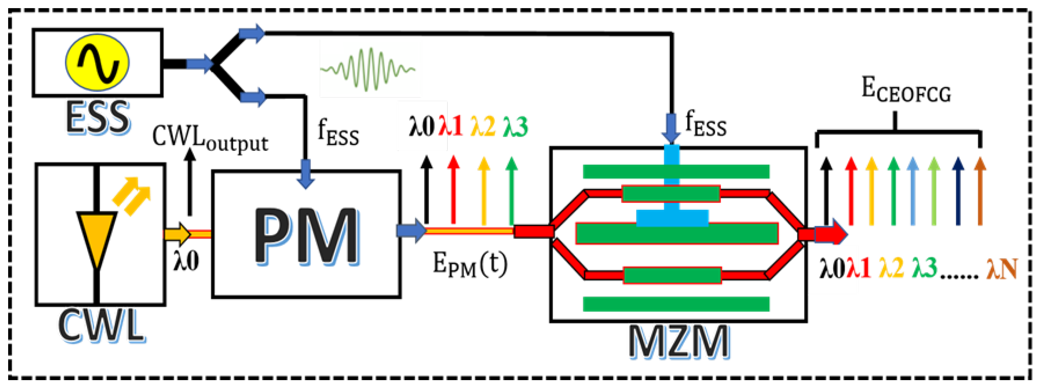
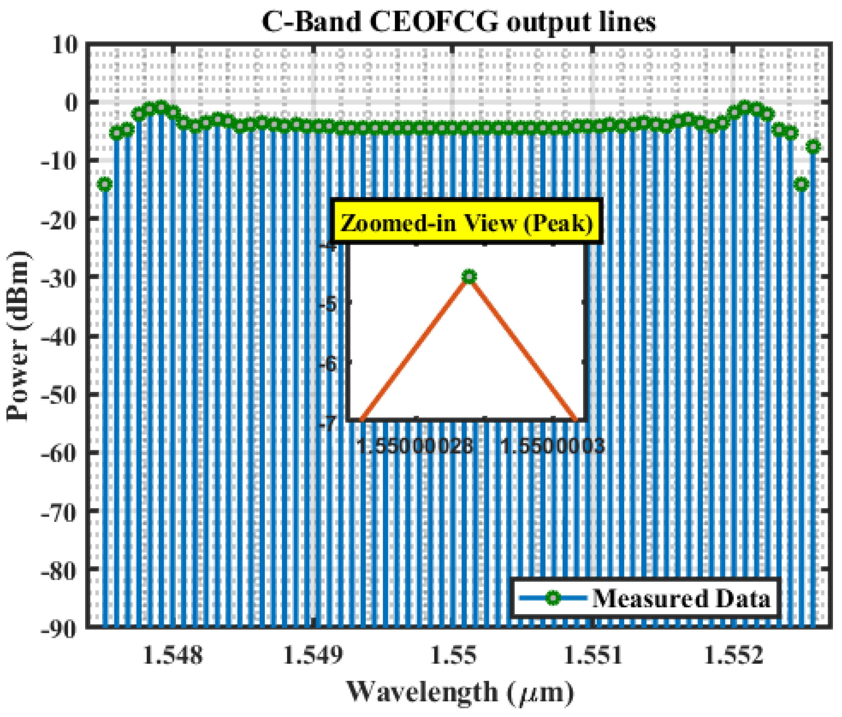
2. Demonstration and Functionality Principle of CEOFCG

An efficient CEOFCG scheme is proposed by using the simple configuration of a continuous-wave laser (CWL) with the series combination, one phase modulator (PM), one Mach Zehnder modulator (MZM), and Electrical Sine Waveform (ESS); this generates the dive electrical signal for both modulators. This CEOFCG scheme provides efficient multiple lines at the output, as shown in Figure 2. The CWL operates at a wavelength of 1550 nm with a line width equal to 100 12 MHz, and output power is kept at 8 dBm. A broader and flattened spectrum is achieved, containing more than 60 frequency comb lines. The frequency spacing for this system is 10 GHz, and the length of fiber used for the transmission is 100 × N , where N = 16, 25, 32, 40, and 50 km SSMF (standard single-mode fiber), and all these produced CEOFCG tones exist in the C band. Equally spaced C-Band CEOFCG output lines are shown in Figure 3.
CEOFCG enhances the performance of WDM systems, and the CWL is the only channel version transmitter component in the WDM system. The dynamics of the CWL are adjusted based on some parameters like signal amplitude ( A m ), power (P), and phase noise ( φ n ). An exponential function e ± j ( 2 π ν f t + φ n ) can be used to represent the phase of a signal. In this expression, ( 2 π ν f ) is the angular frequency, which describes how rapidly the signal oscillates in radians per second, while t represents time. The j represents the imaginary unit (±) is could indicate (signal propagation) that the signal could have a positive or negative phase shift. These parameters are used to find the output of the CWL. The probability density function (PDF) represents φ n [19,27,28]. Laser output ( C W L output ) is represented in Equation (1).
C W L output ( t ) = A m e ± j ( 2 π ν f t + φ n )
C W L output ( X ) C W L output ( y ) = P 1 / 2 ( 1 m ) 1 / 2 e j θ ( m ) 1 / 2
tan ( 2 α ) = 2 cos θ ( 1 m 2 ) 1 / 2 1 2 m &
sin ( φ ) = 2 sin θ ( 1 m 2 ) 1 / 2
The state of the polarization-based output is multiplied by a complex vector. Here, m is the split ratio, α (azimuth) and φ (ellipticity), represent the phase difference θ interrelated parameters.
f ( Δ φ n ) = e Δ φ n / ( 4 π Δ f d t ) 2 π ( Δ f d t ) 1 / 2
In Equation (2), time discretization is d t , Δ f linewidth and Δ φ n represents the phase difference between two simultaneous instants with a supposed variance 2 π ( Δ f ) 1 / 2 and zero means. The amount of Δ f is equal to half of the maximum power spectrum of the laser. The driving input electrical signal E S S Spectrum drives the PM ( A PM cos ( 2 π f 1 t ) ) and MZM ( A MZM cos ( 2 π f 2 t + Δ φ ) ), and Equation (4) represents this spectrum. Here, f 1 = f 2 = f ESS = 12 GB and A PM , A MZM represent the amplitude of the ESS. The ESS imposes a PM on an optical carrier [29,30].
E PM ( t ) = C W L output ( t ) e j β 1 cos ( 2 π f 1 t )
Here, E PM is an optical signal output from the PM, and Equation (3) represents this output. Finally, modulation indexing is β 1 = π A PM V PM π 1 , V PM π 1 is the half-wave voltage PM [27,28].
E CEOFCG = E MZM E PM ( t ) e j ( φ 1 + β 2 cos ( 2 π f 2 t + Δ φ ) ) e j β 2 cos ( 2 π f 2 t + Δ φ )
In Equation (4), β 2 = π A MZM V MZM π 2 , V MZM π 2 is the half-wave voltage of MZM, and φ 1 = π V b ( D C ) V MZM π 2 is the phase shift introduced by the bias voltage; Δ φ is the phase difference of the ESS injected into MZM based on the Jacobi-Anger expansion of E CEOFCG , and it is derived as in [18,19,27,28].
E CEOFCG = 1 2 C W L output ( t ) p = e j G Δ φ e j φ 1 + e j p π × J p ( β 1 ) J q ( β 2 ) e j ( p + q ) ω ESS t
In Equation (5), J p and J q represent the p-th and q-th order of the Bessel function. Here, p and q are the n-th order of the Bessel functions, and modulation sidebands are introduced from the MZM, and PM in Equation (5) demonstrates the harmonic components generated by the frequency spacing of ω ESS / 2 π , which equals the oscillating frequency, while G is used as constant to control the phase change [19,27,31].

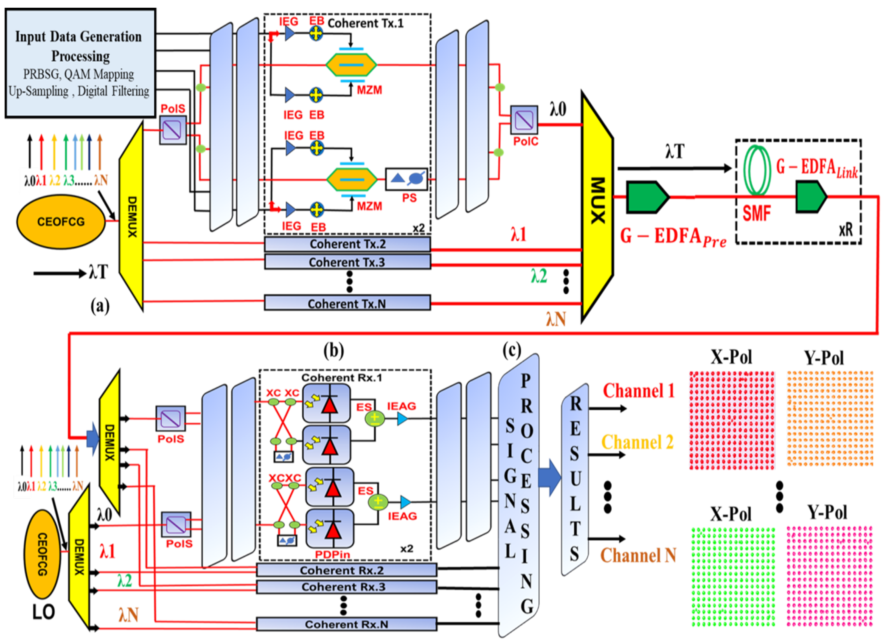
3. Simulation Setup for DP-WDM-256 QAM CEOFCG-Based Coherent Optical Communication System with DSP

In the proposed coherent optical communication system with DSP, a CEOFCG is utilized to replace multiple optical sources typically required in WDM systems. This approach is cost-effective and also minimizes power consumption. A 256-QAM-based WDM coherent optical communication system (COC) and dual-polarization (DP) with proposed CEOFCG is illustrated in Figure 4. COC consists of three main parts: input data generation processing, coherent transmitter (Tx) with CEOFCG, and coherent receiver (Rx). Output data generation is performed using DSP.
PRBSG generates the bit sequence for different operational modes, followed by QAM = 256 mapping and pulse-shaping through upsampling. Digital FIR filtering with a roll-off factor of 0.2 further mitigates bandwidth limitations and provides pre-compensation. After data generation processing, the input signal passes through IEB and EB with specific gains and biases. The CEOFCG output, consisting of approximately 64 carriers, is fed into the WDM-DMUX, which splits the carriers into individual channel outputs with different frequencies. The output is filtered using rectangular optical filters with a bandwidth of 2 GHz [32]. The separated carriers are modulated using IQ modulators in the DP-MZM, where the digital data encode complex symbols to modulate the amplitude and phase of each optical carrier. The DP-MZM has a 60 dB extinction ratio, 27 dB insertion loss, and 3 V switching bias. The modulator outputs are combined using a polarization coupler and sent to the WDM-MUX. After multiplexing, the signal is amplified in a G-EDFA pre-amplifier to attain suitable power for transmission over an SMF link. The losses in each span of the SMF link are compensated by additional suitable SMF link gain.
The accumulated spontaneous emission from the G-EDFAPre and G-EDFA link will reduce the received OSNR. Figure 5a shows the optical signal spectrum of the transmitted and received signal. Transmission via SMF spans over 100 km, and the received signal is fed to the WDM-DMUX. The output signal is split into Nth signals. Here, N is the number of output channel ports. Each channel is de-multiplexed, and the waveforms are detected in a DP coherent receiver using the CEOFCG-based oscillator, the frequency of which is matched to the channel of interest. The CEOFCG oscillator can generate multiple carriers according to the channel setting of the DE-MUX, facilitating the replacement of multiple local oscillators with a single CW-based CEOFCG oscillator. On the Rx side, the output signal is not cleared after coherent receiver detection. The output signal includes a lot of impairments for which DSP compensates. After DP coherent detection of the WDM QAM-256 signal, four main functions are performed in the digital domain before signal detection. The DP coherent receiver provides the four-output lines or imaginary and phase lines (Ip, Iq) and (Qp, Qq). The analog to digital (A/D) conversion (downsampling process) is first performed in DSP. In this work, an 8-bit sampling rate was selected; however, the sampling rate can be changed.

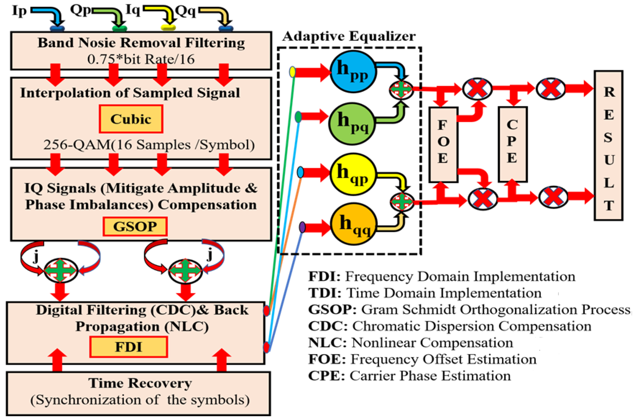
4. Technical Description of DSP Algorithm

After DP-coherent detection, the DSP performs the 256-QAM modulation format using DP channel (Pth & Qth) multiplexing, as shown in Figure 6 [27].
The DSP algorithm includes three preprocessing stages (normalization, DC blocking, and the addition of noise into a signal) [27]. The 256-QAM output signal is normalized, and DC blocking is applied to counter faulty biased modulator voltages. Noise is added and rehabilitated to interact with the transmission channel bandwidth. A Bessel filter with an optimum bandwidth of 0.75 times the symbol rate eliminates band noise. The signals are upsampled for 256-QAM ( 8 × S a m p l e s / b i t ) . Resampling is carried out to match the symbol rate and number of symbols. IQ compensation is utilized to mitigate amplitude and phase imbalances caused by unsuitable MZM bias voltage, bias drift, and responsivity mismatches. The Gram-Schmidt Orthogonalization Process (GSOP) balances the data samples by converting non-orthogonality to orthogonality. Chromatic dispersion compensation (CDC) and nonlinear compensation (NLC) are performed, resulting in fiber-like modulation and nonlinear enhancements (NLEs) [23]. Time-domain FIR and backpropagation (BP) compensate for CDC and NLC, respectively [24]. Digital filtering introduces a time delay that affects symbol synchronization. Better synchronization relies on appropriate sampling phase and frequency. Sampling frequency determines the sampling rate, while the sampling phase ensures accurate symbol timing. Adaptive time recovery governs symbol synchronization. The BEAE method compensates for residual chromatic and polarization mode dispersion and minimizes inter-symbol interference. In simulations, the BEAE with the RDCM algorithm controls channel and polarization mode equalization in the DPol-DeMux system by reducing the error between the BEAE output and a constant. The RDCM algorithm is used as the first stage, while the LMSDD algorithm serves as the second stage for convergence. While the error value for perfect equalization reaches zero for PSK base signals, it cannot reach zero for QAM-256 signals [9,31]. According to [29], RDCM and LMSDD perform better in higher-order modulation formats. The DSP algorithm includes FOE and CPE recovery to compensate for the offsets introduced by the CEOFCG-based oscillator. FOE primarily addresses phase offsets, and methods like differential and spectral (FFT) are commonly used. CPE utilizes feedforward (Viterbi-Viterbi) and decision direct (DD) feedback maximum-likelihood methods [28,29,30,31,33]. A DSP algorithm generates simulation-based results that demonstrate constellation diagrams for QAM (X&Y channels) after transmission over a range of distances.

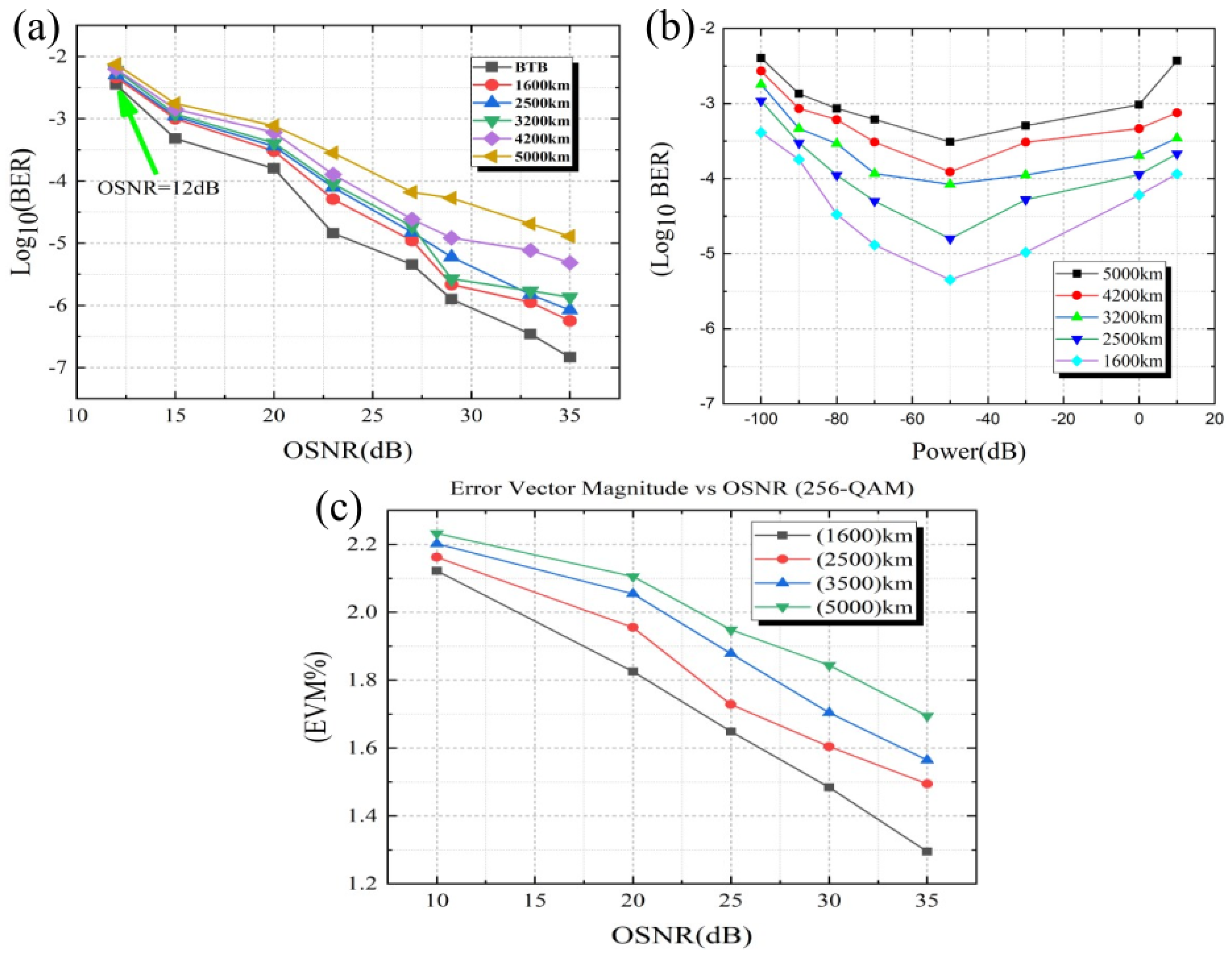
5. Scheme Results and Description

Receiver side impairments were controlled by reimbursing GSOP for relative delays owing to alterations in the radio frequency cable lengths in the I & Q legs of the DP-coherent receiver. The chromatic dispersion compensation over different lengths of SSMF is improved by FDI filtering for every polarization. LMS is used for the polarization of DE-MUX and the equalization of the signal. Then, the waveform was resampled independently for each polarization at twice the symbol rate. Figure 7 shows the simulation results of the 320b/s-20Gbaud and QAM-256 DP-coherent CEOFCG-based WDM system over the single-mode fiber. In Figure 7a, a reasonable value of the log 10 (BER) (bit error ratio) performance according to the OSNR is achieved for back-to-back (BtB) and five different distance values for fiber. This figure clearly shows that the increment in the distance of fiber requires a higher OSNR value for better log 10 (BER) performance. Figure 5b shows the received 256-QAM constellations output from the 1550 nm line, with both polarizations (marked X and Y) at the corresponding bit error rates (BERs) of 7.63172353 × 10 6 , respectively. In this simulation-based analysis, enabling transmitter and receiver performance quantification in the case of an ideal situation like adaptive white Gaussian noise (AWGN), as well as the advantages of the combs compared to the simple laser, are achieved. We also utilized a CW laser-based CEOFCG comb generator as LO, which allows for the reception of the data channel. Figure 7b shows the log 10 (BER) performance concerning the different launched power of a signal after being reserved at multiple values of the SSMF fiber link; Figure 7c shows the comparison of the OSNR. The constellation diagram’s Error Vector Magnitude (EVM) was calculated for different distance values. The value of the EVM% is high at low OSNR values over the different distances, but with little increments in OSNR values, the EVM% reduces, and we obtain more efficient output with low penalties in terms of OSNR. The OSNR is the most important parameter associated with a given optical signal. It is a measurable (practical) quantity for a given network and can be calculated from the given system parameters in Table 1. The cancellation output, as shown in Figure 5, achieves a 1.7 EVM% value.
The use of higher-order modulation formats requires a higher optical signal-to-noise ratio (OSNR), which may result in a significantly reduced achievable transmission distance. The following diagram shows the OSNR estimation stage for high-speed optical communication. A CEOFCG-based WDM DP-256-QAM long-haul optical communication system, achieving 320 Gbit/s per channel and 64 × 20 GBaud (giga-baud) over a variety of SMF lengths, is demonstrated.

6. Conclusions and Future Work

This paper highlights the significance of CEOFCG in various applications and presents a cost-efficient and practical method for its implementation. The proposed CEOFCG design successfully achieves 64 comb lines and demonstrates improved performance in a DP 256-QAM WDM coherent system. The DSP algorithm enables practical phase estimation, compensation of nonlinear impairments, and dispersion in the optical fiber while maintaining low power consumption. CEOFCG serves as a replacement for the local oscillator, reducing sub-channel requirements and maximizing spectral efficiency. The work showcases the potential for performance improvements and power savings in comb-based WDM coherent DP optical fiber communication systems. Future research can focus on hardware implementation and on-chip development of CEOFCG and its applications in terahertz frequencies and precision metrology.

Author Contributions

Conceptualization, B.A., G.M. and H.M.B.; methodology, B.A., G.M., M.R. and Z.U.; software, T.M. and M.R.; investigation, B.A. and Z.U.; writing—original draft preparation, B.A., G.M., H.M.B. and M.R.; writing—review and editing, H.M.B. and T.M.; supervision, H.M.B. and T.M. All authors have read and agreed to the published version of the manuscript.

Funding

This research received no external funding.

Institutional Review Board Statement

Not applicable.

Informed Consent Statement

Not applicable.

Data Availability Statement

The data are included in the manuscript or can be obtained upon request from the corresponding author.

Acknowledgments

This research is supported by the Prince Sultan University, Riyadh, Saudi Arabia. The authors are thankful for the support.

Conflicts of Interest

The authors declare no conflicts of interest.

References

  1. Ohara, T.; Takara, H.; Yamamoto, T.; Masuda, H.; Morioka, T.; Abe, M.; Takahashi, H. Over-1000-channel ultradense WDM transmission with supercontinuum multicarrier source. J. Light. Technol. 2006, 24, 2311. [Google Scholar] [CrossRef]
  2. Fortier, T.M.; Kirchner, M.S.; Quinlan, F.; Taylor, J.; Bergquist, J.; Rosenband, T.; Lemke, N.; Ludlow, A.; Jiang, Y.; Oates, C.; et al. Generation of ultrastable microwaves via optical frequency division. Nat. Photonics 2011, 5, 425–429. [Google Scholar] [CrossRef]
  3. Torres-Company, V.; Weiner, A.M. Optical frequency comb technology for ultra-broadband radio-frequency photonics. Laser Photonics Rev. 2014, 8, 368–393. [Google Scholar] [CrossRef]
  4. Mazur, M.; Lorences-Riesgo, A.; Schröder, J.; Andrekson, P.A.; Karlsson, M. 10 Tb/s PM-64QAM self-homodyne comb-based superchannel transmission with 4% shared pilot tone overhead. J. Light. Technol. 2018, 36, 3176–3184. [Google Scholar] [CrossRef]
  5. Diamantopoulos, N.; Hayashi, M.; Yoshida, Y.; Maruta, A.; Maruyama, R.; Kuwaki, N.; Takenaga, K.; Uemura, H.; Matsuo, S.; Kitayama, K. Mode-selective optical packet switching in mode-division multiplexing networks. Opt. Express 2015, 23, 23660–23666. [Google Scholar] [CrossRef]
  6. Mahmood, A.; Exel, R.; Sauter, T. Impact of hard-and software timestamping on clock synchronization performance over IEEE 802.11. In Proceedings of the 2014 10th IEEE Workshop on Factory Communication Systems (WFCS 2014), Toulouse, France, 5–7 May 2014; IEEE: Piscataway, NJ, USA, 2014; pp. 1–8. [Google Scholar]
  7. Liu, W.; Yang, T.; Chen, X.; Shi, S. A novel DSP scheme for eliminating the interaction between dispersion and transient frequency offset in optical burst-mode coherent systems. Opt. Commun. 2021, 482, 126610. [Google Scholar] [CrossRef]
  8. Tian, F.; Zhang, X.; Xi, L.; Stark, A.; Ralph, S.E.; Chang, G.K. Experiment of 2.56-Tb/s, polarization division multiplexing return-to-zero 16-ary quadrature amplitude modulation, 25 GHz grid coherent optical wavelength division multiplexing, 800 km transmission based on optical comb in standard single-mode fiber. Opt. Eng. 2013, 52, 116103. [Google Scholar] [CrossRef]
  9. Yu, J.; Dong, Z.; Chi, N. 1.96 Tb/s (21 × 100 Gb/s) OFDM Optical Signal Generation and Transmission Over 3200-km Fiber. IEEE Photonics Technol. Lett. 2011, 23, 1061–1063. [Google Scholar] [CrossRef]
  10. Hillerkuss, D.; Schmogrow, R.; Meyer, M.; Wolf, S.; Jordan, M.; Kleinow, P.; Lindenmann, N.; Schindler, P.C.; Melikyan, A.; Yang, X.; et al. Single-laser 32.5 Tbit/s Nyquist WDM transmission. J. Opt. Commun. Netw. 2012, 4, 715–723. [Google Scholar] [CrossRef]
  11. Ludlow, A.D.; Boyd, M.M.; Ye, J.; Peik, E.; Schmidt, P.O. Optical atomic clocks. Rev. Mod. Phys. 2015, 87, 637. [Google Scholar] [CrossRef]
  12. Fortier, T.; Baumann, E. 20 years of developments in optical frequency comb technology and applications. Commun. Phys. 2019, 2, 153. [Google Scholar] [CrossRef]
  13. Ataie, V.; Temprana, E.; Liu, L.; Myslivets, E.; Kuo, B.P.P.; Alic, N.; Radic, S. Ultrahigh count coherent WDM channels transmission using optical parametric comb-based frequency synthesizer. J. Light. Technol. 2015, 33, 694–699. [Google Scholar] [CrossRef]
  14. Puttnam, B.J.; Luis, R.S.; Klaus, W.; Sakaguchi, J.; Mendinueta, J.M.D.; Awaji, Y.; Wada, N.; Tamura, Y.; Hayashi, T.; Hirano, M.; et al. 2.15 Pb/s transmission using a 22 core homogeneous single-mode multi-core fiber and wideband optical comb. In Proceedings of the 2015 European Conference on Optical Communication (ECOC), Valencia, Spain, 27 September–1 October 2015; IEEE: Piscataway, NJ, USA, 2015; pp. 1–3. [Google Scholar]
  15. Temprana, E.; Myslivets, E.; Kuo, B.P.; Liu, L.; Ataie, V.; Alic, N.; Radic, S. Overcoming Kerr-induced capacity limit in optical fiber transmission. Science 2015, 348, 1445–1448. [Google Scholar] [CrossRef] [PubMed]
  16. Chatterjee, B.C.; Ba, S.; Oki, E. Fragmentation problems and management approaches in elastic optical networks: A survey. IEEE Commun. Surv. Tutor. 2017, 20, 183–210. [Google Scholar] [CrossRef]
  17. Pfeifle, J.; Vujicic, V.; Watts, R.T.; Schindler, P.C.; Weimann, C.; Zhou, R.; Freude, W.; Barry, L.P.; Koos, C. Flexible terabit/s Nyquist-WDM super-channels using a gain-switched comb source. Opt. Express 2015, 23, 724–738. [Google Scholar] [CrossRef] [PubMed]
  18. Ullah, R.; Bo, L.; Ullah, S.; Yaya, M.; Tian, F.; Khan, M.K.; Xiangjun, X. Flattened optical multicarrier generation technique for optical line terminal side in next generation WDM-PON supporting high data rate transmission. IEEE Access 2018, 6, 6183–6193. [Google Scholar] [CrossRef]
  19. Kakati, D.; Arya, S.C. A 640-Gbps, 15.2344-b/s/Hz full-duplex optical fiber/wireless single-channel coherent communication system using IQM-based DP-256-QAM and DSP techniques. Photonic Netw. Commun. 2020, 39, 26–38. [Google Scholar] [CrossRef]
  20. Liu, J.; Lucas, E.; Raja, A.S.; He, J.; Riemensberger, J.; Wang, R.N.; Karpov, M.; Guo, H.; Bouchand, R.; Kippenberg, T.J. Photonic microwave generation in the X-and K-band using integrated soliton microcombs. Nat. Photonics 2020, 14, 486–491. [Google Scholar] [CrossRef]
  21. Shen, B.; Chang, L.; Liu, J.; Wang, H.; Yang, Q.F.; Xiang, C.; Wang, R.N.; He, J.; Liu, T.; Xie, W.; et al. Integrated turnkey soliton microcombs. Nature 2020, 582, 365–369. [Google Scholar] [CrossRef]
  22. Hu, H.; Da Ros, F.; Pu, M.; Ye, F.; Ingerslev, K.; Porto da Silva, E.; Nooruzzaman, M.; Amma, Y.; Sasaki, Y.; Mizuno, T.; et al. Single-source chip-based frequency comb enabling extreme parallel data transmission. Nat. Photonics 2018, 12, 469–473. [Google Scholar] [CrossRef]
  23. Chen, M.; Peng, M.; Zhou, H.; Zheng, Z.; Tang, X.; Maivan, L. Receiver sensitivity improvement in spectrally-efficient guard-band twin-SSB-OFDM using an optical IQ modulator. Opt. Commun. 2017, 405, 259–264. [Google Scholar] [CrossRef]
  24. Nguyen, T.H.; Scalart, P.; Gay, M.; Bramerie, L.; Sentieys, O.; Simon, J.C.; Peucheret, C.; Joindot, M. Blind transmitter IQ imbalance compensation in M-QAM optical coherent systems. J. Opt. Commun. Netw. 2017, 9, D42–D50. [Google Scholar] [CrossRef]
  25. Zhu, Y.; Jiang, M.; Ruan, X.; Chen, Z.; Li, C.; Zhang, F. 6.4 Tb/s (32× 200 Gb/s) WDM direct-detection transmission with twin-SSB modulation and Kramers–Kronig receiver. Opt. Commun. 2018, 415, 64–69. [Google Scholar] [CrossRef]
  26. Cutrona, A.; Rowley, M.; Das, D.; Olivieri, L.; Peters, L.; Chu, S.T.; Little, B.E.; Morandotti, R.; Moss, D.J.; Totero Gongora, J.S.; et al. High parametric efficiency in laser cavity-soliton microcombs. Opt. Express 2022, 30, 39816–39825. [Google Scholar] [CrossRef]
  27. OptiSystem. Available online: https://optiwave.com/privacy-policy/ (accessed on 31 January 2025).
  28. Armstrong, J. Theory of interferometric analysis of laser phase noise. J. Opt. Soc. Am. 1966, 56, 1024–1031. [Google Scholar] [CrossRef]
  29. Godard, D. Self-recovering equalization and carrier tracking in two-dimensional data communication systems. IEEE Trans. Commun. 1980, 28, 1867–1875. [Google Scholar] [CrossRef]
  30. Werner, J.J.; Yang, J. Generalized Multimodulus Technique for Blind Equalization. US Patent 5,940,440, 17 August 1999. [Google Scholar]
  31. Zhou, X.; Nelson, L.E.; Magill, P.; Isaac, R.; Zhu, B.; Peckham, D.W.; Borel, P.I.; Carlson, K. High spectral efficiency 400 Gb/s transmission using PDM time-domain hybrid 32–64 QAM and training-assisted carrier recovery. J. Light. Technol. 2013, 31, 999–1005. [Google Scholar] [CrossRef]
  32. Torres-Ferrera, P.; García-Yáñez, M.; Gutiérrez-Castrejón, R.; Tomkos, I. Coherent optical WDM systems for 1.6 Tb/s Ethernet over 40 km of single-mode fiber. Opt. Fiber Technol. 2018, 43, 180–187. [Google Scholar] [CrossRef]
  33. Du, L.B.; Lowery, A.J. Improved single channel backpropagation for intra-channel fiber nonlinearity compensation in long-haul optical communication systems. Opt. Express 2010, 18, 17075–17088. [Google Scholar] [CrossRef]
Figure 1. Optical frequency comb applications (FC invention has the advantages of combining robustness and simplicity; FC is, thus, extremely valuable in the above-defined fields).
Chips 04 00016 g001
Figure 2. Schematic representation of CEOFCG. CWL: Continuous-wave laser; ESS: Electrical Sine Waveform signal; PM: Phase modulator; MZM: Mach-Zehnder modulator. The comb lines are represented by colored arrows (for clarity), while the stages are indicated by small horizontal arrows or alternate colored arrows. It is easier to understand how multiple channels can be formed from a single optical carrier.
Chips 04 00016 g002
Figure 3. Representing the equally spaced C-Band CEOFCG output lines.
Chips 04 00016 g003
Figure 4. The illustration shows how a numerical model reflecting the CEOFCG application in a dual-polarization 256-QAM-based WDM coherent optical communication system is detailed. Here, CEOFCG is used as a laser source at the Tx and as LO on the Rx. MUX: Multiplexing; DE-MUX: De-multiplexing; LO: Local oscillator; Pols: Polarization splitter; IEAG: Electrical amplifier gain; IEG: Electrical gain; EB: Electrical bais; Polc: Polarization combiner; MZM: Mach-Zehnder modulator; PS: Phase shift; ES: Electrical subtractor; XC: X-coupler; PDPin: Photodetector pin diode. Sub-figure in the bottom left shows the dual-polarization output signals using 256-QAM modulation (X and Y polarizations). The polarization components of each channel are distinguished by distinct colors. Such as the first channel X and Y polarizations are shown by yellow and red, whereas the N channel X and Y polarizations are shown by green and magenta.
Chips 04 00016 g004
Figure 5. (a) This study compares the optical spectrum of DP coherent CEOFCG based WDM QAM-256 systems before and after the addition of an SMF link; the next variety of links were then analyzed in the SMF network 100 × N , N = [ 16 , 25 , 32 , 42 , 50 ] ; (b) this represents the CEOFCG-based WDM DP-256-QAM constellations of long-haul optical communication system output with 320 Gbit/sper channel and 1.7% EVM over the SMF.
Chips 04 00016 g005
Figure 6. Technical demonstration of the DSP algorithm.
Chips 04 00016 g006
Figure 7. High-performance transmission is achieved at a data rate of 320 Gbit/s per channel and 64 × 20 GBaud via an SMF link using the CEOFCG-based WDM DP-256-QAM long-haul optical communication system model, as shown in Figure 4. (a) The illustration shows the correlation between OSNR vs. log 10 (BER) for different single-mode fiber (SSMF) lengths. (b) Comparison of launch power vs. log 10 (BER), according to the different values of SSMF length. (c) The error magnitude value (EVM%) vs. OSNR, according to the different values of SSMF length.
Chips 04 00016 g007
Table 1. Transmission and link parameters.
Name of ParametersParameters Values
Transmission Parameter
Symbol Rate20 Gsymbol/s
Modulation FormatDP-256 QAM
Bit Rate320 Gbit/s
Number of Samples524,288
Reference Wavelength1550 nm
Guard Bits20 Guard bits
Link Parameter
Attenuation of Fiber0.2 dB/km
Dispersion Coefficient16.75 ps/nm/km
Nonlinearity of Fiber1.2 (W.km)−1
Gain in EDFA16 dB
Noise Figure of EDFA4.5 dB
Disclaimer/Publisher’s Note: The statements, opinions and data contained in all publications are solely those of the individual author(s) and contributor(s) and not of MDPI and/or the editor(s). MDPI and/or the editor(s) disclaim responsibility for any injury to people or property resulting from any ideas, methods, instructions or products referred to in the content.

