Article

Evaluation of Coconut Fiber in Corroded Reinforced Self-Healing Concrete Using NDT Methods

by
Ahmad Zaki
1,2,*,
Nabilah Cantika Aprilia
1,
Sri Atmaja P. Rosyidi
1 and
Khairil Mahbubi
2
1
Department of Civil Engineering, Faculty of Engineering, Universitas Muhammadiyah Yogyakarta, Bantul, Daerah Istimewa Yogyakarta, Yogyakarta 55183, Indonesia
2
Magister of Civil Engineering, Postgraduate Programme, Universitas Muhammadiyah Yogyakarta, Bantul, Daerah Istimewa Yogyakarta, Yogyakarta 55183, Indonesia
*
Author to whom correspondence should be addressed.
NDT 2024, 2(3), 214-227; https://doi.org/10.3390/ndt2030013
Submission received: 2 June 2024 / Revised: 3 July 2024 / Accepted: 8 July 2024 / Published: 11 July 2024
(This article belongs to the Topic Nondestructive Testing and Evaluation)

Abstract

:
The incorporation of natural fibers into concrete has recently emerged as a popular approach in the field of construction materials due to its sustainability and environmental friendliness. In comparison to artificial fibers, natural fibers are more cost-effective and widely available globally. Among the various natural fibers, coconut fiber (CF) stands out for its unique set of advantages. This study aims to investigate the mechanical properties and durability of coconut-fiber-reinforced self-healing concrete (CFR-SHC) in the context of corrosion resistance. Additionally, Bacillus subtilis bacteria (10% by mass) was incorporated into the CFR-SHC. The impact of ±50 mm long CF with varying contents of 0.25%, 0.5%, and 0.75% by mass was examined. Specimens were subjected to corrosion acceleration for 48, 96, and 168 h. Non-destructive testing (NDT) methods of Electrical Resistivity (ER) and Impact Echo (IE) were conducted to test the corrosion resistance. The experimental results demonstrate that CFR-SHC increased the compressive strength by 6% and the flexural strength by 40%. CFR-SHC also exhibits excellent resistance to corrosion, characterized by low inrush current, high ER value, and high IE frequency. The most favorable overall outcomes were observed for the CFR-SHC sample containing 0.5% of the cement mass.

1. Introduction

Concrete structures are the main elements in modern building construction and urbanization due to their versatility and high mechanical strength. Concrete, composed of cement, water, sand, and coarse aggregates, is popular because it is easily adaptable, has good insulation, is fire-resistant, and its materials are readily available and inexpensive [1]. However, the high demand for concrete due to urbanization and industrial growth has adverse environmental impacts. Portland cement, the primary component of concrete, requires significant energy in its production, releasing approximately 0.9 kg of greenhouse gases per kilogram of cement produced [2,3]. The extraction of other components, such as fine and coarse aggregates, also damages the environment, though not as significantly as cement. Overall, concrete production contributes to 8% of global greenhouse gas emissions [4,5]. Despite concrete’s high strength and durability, as well as its low production and maintenance costs, its weakness lies in its low tensile strength and brittle nature. To overcome this weakness, steel reinforcement is added to concrete to enhance its tensile strength, commonly referred to as reinforced concrete (RC) [6].
Fibers are added to concrete to improve its tensile strength, resulting in a specialized type of concrete known as fiber-reinforced concrete (FRC) [7,8]. In addition to secondary cementitious materials that help create eco-friendly concrete, natural fibers have become one of the most popular reinforcing materials due to their sustainability and environmental friendliness [9]. Natural fibers are widely available globally, cheaper than synthetic fibers, stiffer, and recyclable [10]. Coconut fiber (CF), a popular natural fiber derived from the coir of ripe coconuts, has low thermal conductivity but is strong and stiff, increasing the tensile, flexural, and compressive strength of concrete while reducing its weight [11,12]. Due to the many advantages of natural fibers, including their wide availability, light weight, low cost, and ease of production, natural fiber-based biocomposites have widely replaced synthetic plastics in various applications [13]. Many countries worldwide, especially in tropical and subtropical regions like Indonesia, cultivate coconuts, which play a significant role in economic growth [14].
Any type of RC exposed to extreme environmental conditions will experience deterioration, from cracking to damage caused by corrosion [15]. Corrosion of the steel reinforcement in RC is a primary mechanism of strength degradation in RC structures [16,17]. If concrete cracks are left untreated, corrosion will spread throughout the reinforcement, eventually causing the concrete to collapse [18,19]. Repair and rehabilitation of concrete damage must be conducted swiftly and accurately to extend the service life and ensure the safety of the related components [20]. Self-healing concrete (SHC) is a popular innovation in preventing and repairing concrete deterioration. The self-healing ability of SHC can be self-supporting or assisted, depending on the agent chosen [21,22]. SHC can be a solution to repair cracks, improve the durability of concrete structures, and recover the performance of corrosion-damaged structures [23,24,25].
This study aims to combine coconut-fiber-reinforced self-healing concrete (CFR-SHC) to create a composite expected to combat corrosion. Self-healing is carried out using Bacillus subtilis bacteria as an additive. The use of Bacillus subtilis can reduce the porosity of concrete [26], thereby addressing the drawback of coconut fiber, which otherwise increases porosity due to high water absorption [27]. The quality of the composite concrete can then be assessed through non-destructive testing (NDT), specifically using Electrical Resistivity (ER) and Impact Echo (IE) methods. These NDT methods can evaluate and predict damage, control quality, and detect defects and corrosion without damaging the internal structure [28]. To the best of the authors’ knowledge, this study is the first to assess the performance of CFR-SHC with Bacillus subtilis and evaluation after corrosion. The mechanical strength parameters of concrete, such as compressive and flexural strength, and the durability assessment of the concrete mix, such as ER and IE, are evaluated. The findings of this study encourage the use of CFR-SHC in structural applications subject to corrosion and further evaluation of other parameters in the future.

2. Research Significance

The research holds significant implications for the advancement of sustainable construction materials. By incorporating coconut fibers and Bacillus subtilis bacteria into self-healing concrete, this study addresses critical issues related to the mechanical performance and durability of concrete in corrosive environments. The use of NDT methods, specifically ER and IE, provides robust evidence of the enhanced corrosion resistance offered by the coconut-fiber-reinforced self-healing concrete (CFR-SHC).
These improvements are crucial for extending the lifespan of concrete structures, reducing maintenance costs, and minimizing environmental impact. Moreover, the successful use of natural fibers and microbial agents aligns with global efforts to promote eco-friendly construction practices, providing a cost-effective and accessible solution for sustainable infrastructure development. The research outcomes could guide future innovations in concrete technology and encourage the broader adoption of sustainable materials in the construction industry.

3. Materials and Methods

3.1. Materials

The composite concrete material used has passed and meets the Indonesian standard requirements of the Structural Engineering Laboratory of Universitas Muhammadiyah Yogyakarta. The constituent materials include Portland cement, coarse aggregates, fine aggregates, water, coconut fibers, and Bacillus subtilis bacteria. The Portland cement used is Type I Portland cement with the brand Holcim Dynamix. The fine aggregate used is aggregate with a maximum grain size of 4.76 mm, sourced naturally or processed from Progo, Yogyakarta. The coarse aggregate comes from Clereng, Yogyakarta, in the form of crushed stone with high sulfate resistance, obtained from a stone crushing industry with a grain size between 4.75 mm and 40 mm. The water used is clean water, free from oil, acid, salts, alkali, organic matter, chloride ions, or other substances that can weaken the strength of the concrete or reinforcement. The CF used has a length of approximately 50 mm and has been cleaned [29], also sourced from Yogyakarta, Indonesia. The Bacillus subtilis bacteria used are obtained from the Laboratory of the Faculty of Agriculture, Universitas Muhammadiyah Yogyakarta. CF and bacteria is shown in Figure 1. The addition of bacteria to the concrete is performed using the direct mixing method, which is carried out during the concrete mixing process.
The materials to be used in the production of concrete will be tested to assess their quality before creating test specimens and mix designs. The tests conducted include specific gravity and water absorption, fine aggregate gradation, abrasion, and clay content. Based on the tests, the fine aggregate gradation analysis results fall within gradation zone 2, according to SNI ASTM C136:2014, indicating that the sand is slightly coarse, as shown in Figure 2. The results of fine and coarse aggregate material testing are shown in Table 1.

3.2. Methods

3.2.1. Mix Design

The concrete mix design follows ACI 211.1-91 (2002) procedures for maintaining proportions in the production of normal concrete, as shown in Table 2. The planned concrete quality is 30 MPa with a safety factor of 35%. CF is added to the mix in proportions of 0.25%, 0.50%, and 0.75% of the coarse aggregate. Bacillus subtilis bacteria are added at a proportion of 105 cfu/Ml, with 10 Ml of bacteria per test specimen. The specimen codes are BN for normal concrete and V1, V2, and V3 for CF variations of 0.25%, 0.50%, and 0.75% with 10 Ml of bacteria, respectively.

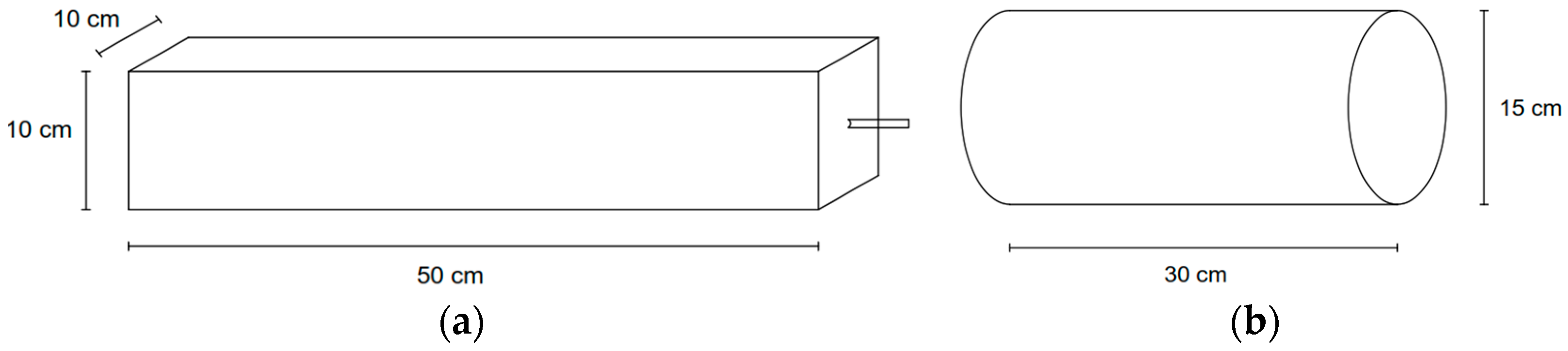
3.2.2. Preparation of Specimens

Specimens were made in the form of beams measuring 50 cm × 10 cm × 10 cm and cylinders measuring 15 cm × 30 cm. The main reinforcement size was Ø12 mm, and cables were attached to the ends of the reinforcement to facilitate the accelerated corrosion process using a DC power supply. Each specimen was prepared based on the mix proportions of Bacillus subtilis bacteria (10 Ml of water) and CF at 0.25%, 0.50%, and 0.75%. The bacteria were added during the mixing of fresh concrete. The mixed concrete was tested for workability during the production process by measuring the slump value. After passing the slump test, with a requirement of 7.5–10 cm, the concrete mix was poured into the molds until fully compacted, ensuring no air voids formed. The concrete was then allowed to harden for 24 h before being removed from the molds and weighed. The sketch of the test specimens can be seen in Figure 3.
After 24 h, the molds were removed from the test specimens, which were then taken to the curing area. Concrete curing was conducted using the immersion method, where the entire surface of the concrete was submerged in water to prevent the concrete from losing water too quickly, maintain moisture, and control the temperature to ensure proper hydration. The curing process was carried out for 28 days.

3.2.3. Acceleration of Corrosion

Beam specimens, aged at least 28 days under curing, undergo accelerated corrosion using the Galvanostatic method to expedite the natural corrosion process, which can be lengthy [30]. Accelerated corrosion testing is conducted by connecting the reinforcement steel bars with one set to the positive pole (+) as the anode and another set to the negative pole (−) as the cathode. A DC power supply is employed to facilitate and regulate the corrosion process by controlling the electric current and duration as needed. This process is carried out for different durations: 48 h, 96 h, and 168 h. The DC power supply has specifications of 3 A and 5 A to accelerate the corrosion process in concrete. A 5% NaCl solution is used based on the volume of water in a Styrofoam box. An illustration of the accelerated corrosion testing can be seen in Figure 4.
Accelerated corrosion testing can be planned to use the principles of Faraday’s Law, which refers to the percentage of weight loss of reinforcement due to the corrosion process. The percentage of weight loss of reinforcement, according to Faraday’s Law equation, can be seen in Equation (1).
m = M   ×   I   ×   t   z   ×   F
where Δm is loss of weight on reinforcement (grams), M is the atomic weight of metal (Ar Fe = 56), I is the electric current (A), t is the corrosion duration (seconds), z is the reacting electrons (z Fe = 2), and F is Faraday’s constant (96,500 A/s).

3.2.4. Compressive Strength and Flexural Strength

Compressive and flexural strength tests were conducted at the Structures and Construction Materials Laboratory of Civil Engineering, Universitas Muhammadiyah Yogyakarta, using a universal testing machine. Compressive strength tests were performed on concrete cylinders cured for 28 days without corrosion (control specimens), as depicted in Figure 5a. Flexural strength testing of concrete beams was conducted after completion of the corrosion process and NDT tests. The test involved applying a load at the center of the beam span, with a distance of 5 cm between the support and the beam edge, as illustrated in Figure 5b.

3.2.5. Electrical Resistivity
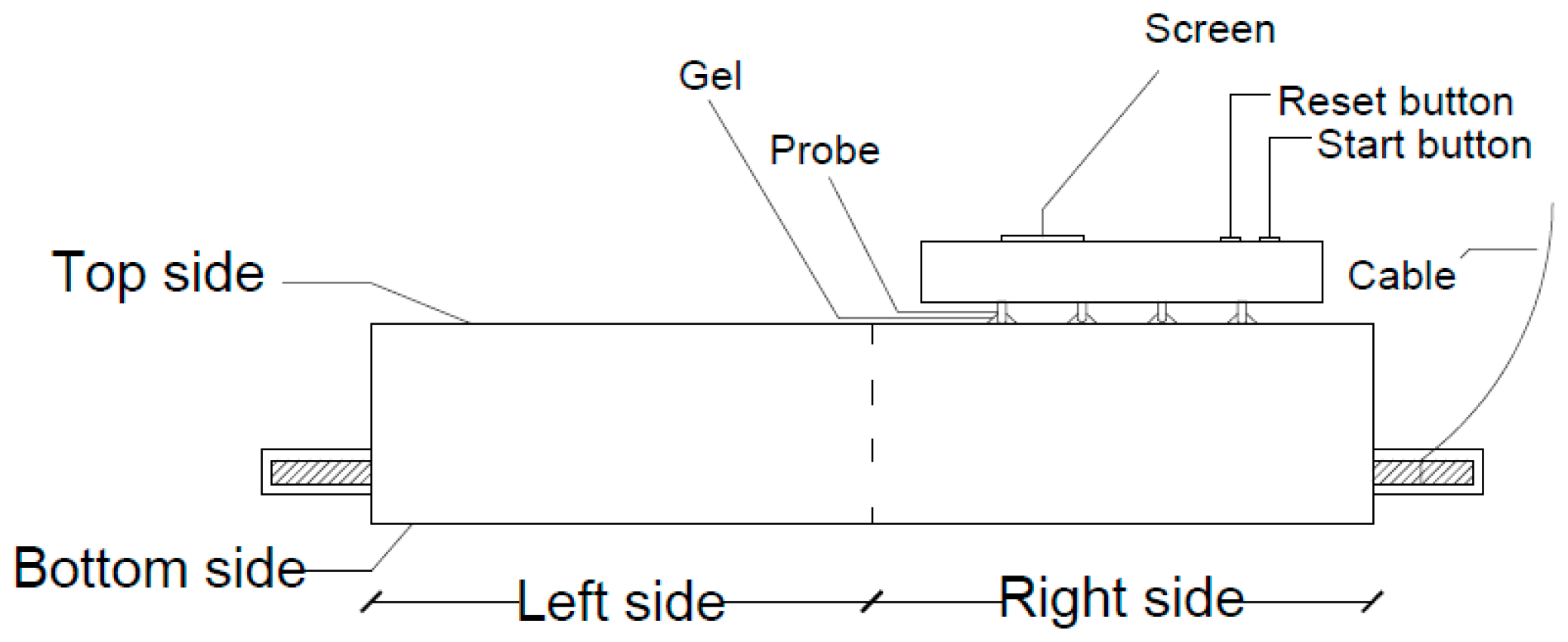
Electrical Resistivity (ER) testing was conducted when the test specimens were 28 days old. This test was carried out before and after the accelerated corrosion process to compare the test results of the corrosion process. To make the data obtained complete and more accurate, the ER measurement tool uses the Four Point Probe method, where each test point is carried out three times. This test uses parameters that have been determined by AASHTO TP 95. Details of the division of points carried out for ER testing can be seen in Figure 6. The side division is divided into 4 areas, namely the upper left and right sides and the lower left and right sides.

3.2.6. Impact Echo

Impact Echo (IE) testing was conducted when the object was 28 days old. This test was conducted before and after the accelerated corrosion process to compare the test results. The IE method is a technique for detecting defects in concrete [31]. This method is based on monitoring surface movement due to short-term mechanical impact. The concrete will be tapped several times using the IE test equipment, and then the sensor will receive the signal at a predetermined distance between the sensor and the impact point. The IE test was conducted with 2 sensors at impact points of 5 cm, 10 cm, 15 cm, and 20 cm, as shown in Figure 7.

4. Results and Discussion

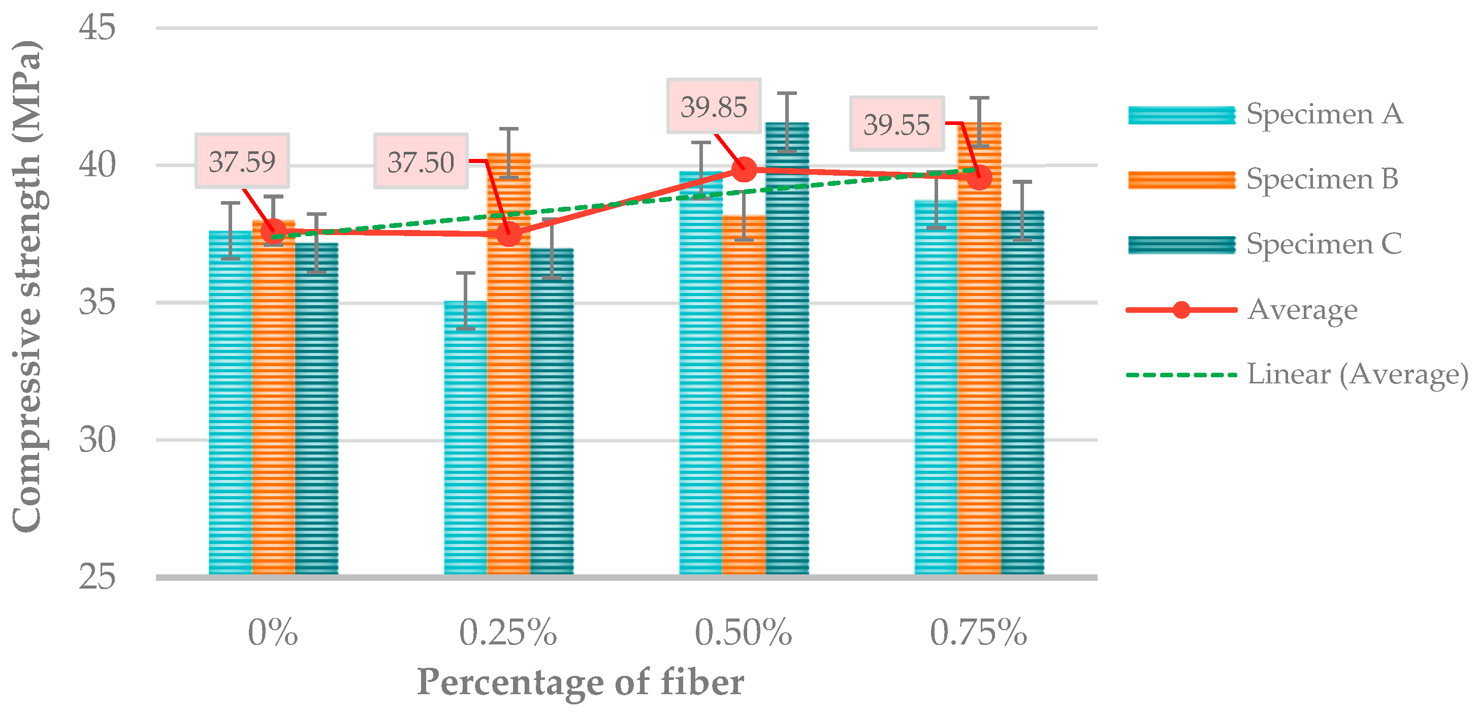
4.1. Compressive Strength

The concrete mix design was made with a planned compressive strength of 30 MPa. The results show that normal concrete has an average compressive strength of 37.59 MPa. The 0.25% CF variation specimen showed an average compressive strength of 37.50 MPa. CF 05% has an average concrete compressive strength of 39.85 MPa. The 0.75% CF variation has an average compressive strength of 39.55 MPa. The compressive strength results in Figure 8 show that normal concrete has a lower compressive strength than CFR-SHC. CF 0.25% does have a smaller compressive strength of 0.09 MPa than normal concrete, but it needs to be considered again because the standard deviation value is also high. The more significant percentage of CF in CFR-SHC is shown to increase the compressive strength up to 39.85 MPa at CF 0.5%, then decrease it slightly by 0.30 MPa at CF 0.75%. The bonding of reinforcing fibers in the specimens has a good impact on the compressive strength. Compression results in lateral expansion, which is limited by CF, increasing compressive strength. Due to their strength, fibers can resist strain and shear [32]. However, the optimum dosage of fiber varies depending on the type of fiber, physical aspects such as length and diameter, as well as the concrete mix design and water-to-binder ratio. A study reported that in CF with 50 mm and 75 mm lengths, the compressive strength decreased as the fiber content increased [1]. The decrease in compressive strength can be attributed to the decreased workability of fresh concrete caused by the increase in fiber content and length, as well as the lack of proper compaction during the casting of the specimens, resulting in the formation of air voids [29].

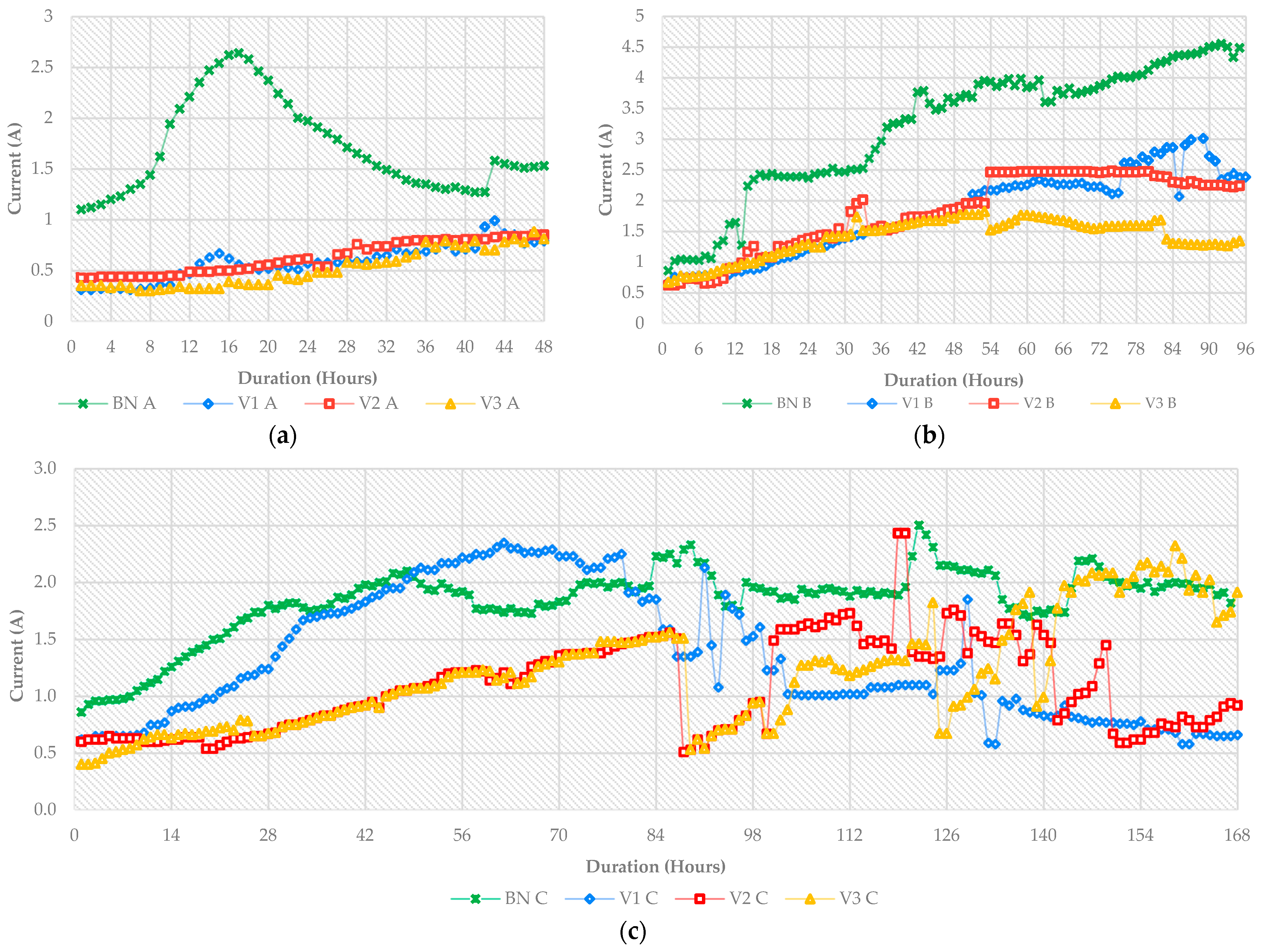
4.2. Accelerated Corrosion

Accelerated corrosion was carried out using durations of 48 h, 96 h, and 168 h on 12 beam test specimens and the current was read every hour to see the increase in current on each test specimen, shown in the graph in Figure 9.
The graph shows that CFR-SHC has a relatively small current compared to normal concrete. The current was monitored every hour to record the average intensity of corrosion current flowing through the specimens at different concrete mixes. This increase in current explains the resistance of the concrete to chloride initiation. In accelerated corrosion with a duration of 48 h, CF 0.75% had lower initial to final current values, followed by concrete mixes CF 0.25%, CF 0.5%, and normal concrete. At 96 h, it was the same case, with 0.75% CF still having a low initial to final current, followed by 0.25% CF, 0.5% CF, and normal concrete. The addition of bacteria and CF influences a more stable and lower current than normal concrete in the first 96 h. At 168 h of accelerated corrosion, the current was unstable; CF 0.75% had the lowest initial current but increased at the end. Normal concrete remained consistently stable and was the highest compared to CFR-SHC. This proves that CFR-SHC has a lower current than normal concrete, which indicates it has better current resistance than normal concrete.
Specimens were crushed to determine the actual reinforcement mass loss due to corrosion after the self-healing process and flexural strength. The reinforcing steel taken from the crushed specimens was cleaned and weighed to determine the percentage mass loss of the reinforcement due to the accelerated corrosion process. The mass loss results were compared with the initial mass of the reinforcement to determine the actual corrosion rate. The duration of accelerated corrosion and the corrosion rate are not directly related, but they are interrelated, as a higher corrosion rate will generally lead to a shorter corrosion duration, but there are other factors that can affect the corrosion process, such as the environment, material properties, and the presence of protective coatings or treatments [33]. The accelerated corrosion test proceeded quite controllably, with the correlation between accelerated corrosion duration and actual corrosion rate at around 90%, which can be seen in Figure 10. The normal concrete had a very low correlation value, because at 13 h BN B experienced initial cracking and resulted in an increase in current, resulting in high chloride penetration, which affected the derivation value. The sudden surge in current indicates the formation of initial corrosion cracking in concrete [34].

4.3. Electrical Resistivity

The ER testing method is carried out to determine the resistance of concrete to reinforcing steel corrosion, where the resistivity value will provide information about the condition of the concrete and the potential for reinforcing steel corrosion in concrete [35]. The corrosion process will be slower if the ER of the concrete is high. The ER of concrete exposed to chloride indicates the risk of early corrosion damage, as low ER is always associated with rapid chloride penetration [36]. This test was conducted on concrete before and after corrosion to see the durability of concrete from different variations of CFR-SHC. ER before corrosion in all normal concrete specimens and CFR-SHC shows ER values that fall into the very low category, as can be seen in Figure 11. However, normal concrete ER has a value that is far below CFR-SHC, for example, for the smallest difference in CF 0.25 and normal concrete, which has a difference of 20.6 kΩ·cm, but still in the very low category in accordance with AASHTO TP 95-14. The ER results after corrosion decreased according to the duration of corrosion. The ER value will decrease as the corrosion rate increases. From the results obtained in the ER test after being corroded, the highest ER value at 48 and 96 h of corrosion acceleration was obtained by 0.5% CF specimens at 40.91 kΩ·cm (very low) and 24.70 kΩ·cm (low), while at 168 h, 0.75% CF specimens obtained the highest ER value at 11.00 kΩ·cm (high).

4.4. Impact Echo

From Figure 12 of the IE test results, peak frequency values were obtained before and after accelerated corrosion. CFR-SHC specimens have higher frequency values than normal concrete. The difference in frequency values can occur due to several factors such as concrete density and the heterogeneous nature of the concrete mix [37]. CFR-SHC has a higher average frequency value than normal concrete, indicating that CFR-SHC has a better density than normal concrete. The highest peak frequency value before corrosion was obtained by 0.75% CF addition concrete at 18,234.33 Hz, while the highest normal concrete was 10,154.62 Hz. After corrosion, the highest frequency was obtained by normal concrete at 48 h of corrosion with a peak frequency of 6449.11 Hz. However, after 168 h of corrosion, normal concrete obtained the smallest frequency, with an optimum of 3740.4 Hz with 0.25% CF. The IE test results obtained show that the higher the level of corrosion in terms of mass loss, the lower the frequency value [37].

4.5. Flexural Strength

Based on the results of the flexural strength test, it was found that, in the process of accelerated corrosion for 48 h, the highest flexural strength was obtained by CF 0.25% at 2.38 MPa, for 96 h by CF 0.5% at 1.59 MPa, and for 168 h also by CF 0.5% at 1.22 MPa. The flexural strength of normal concrete is lower than that of CFR-SHC, as shown in Figure 13. This is because as the level of corrosion increases, the adhesion between concrete reinforcement will weaken. Corrosion will affect the mechanical properties of the reinforcement; in addition, corrosion products cause cracking and then stripping of the surrounding concrete, and severe corrosion levels can cause a decrease in the bearing capacity of structural components [38]. Therefore, normal concrete that has a higher corrosion rate than CFR-SHC has a lower flexural strength value. On the heavy corrosion scale, the addition of 0.5% CF was the optimum in resisting the corrosion rate and managed to maintain the best flexural strength.

4.6. Relationship between RE and IE Values

The relationship between ER and IE needs to be observed to determine the correlation between them and the corrosion of CFR-SHC. Figure 14 shows that the correlation value of ER and IE methods before corrosion is 74% and after corrosion is 41%. The relationship shows that the IE and ER test methods have a strong correlation or relationship in evaluating the condition of the concrete before and after corrosion. The correlation before corrosion is quite strong compared to after corrosion. The weak correlation after corrosion is due to the different CF mixes and hence the different optimum mixes in these two NDT tests against the corrosion rate.

5. Conclusions

In this study, CF with ± 50 mm length and contents (0.25%, 0.5%, 0.75% by weight) were added to self-healing concrete (SHC) reinforced with 10% Bacillus subtilis bacteria to investigate the mechanical properties and durability based on NDT testing (ER and IE) for use in RC corrosion applications. The results of CFR-SHC were compared with normal concrete with the same mix design. The conclusions obtained are as follows:
  • CFR-SHC has lower compressive strength values compared to normal concrete. The addition of 0.25% CF obtained 2% lower strength than normal concrete, but it needs to be noted because of the large standard deviation. Then, the addition of 0.5% and 0.75% increased the compressive strength up to 6% compared to normal concrete by 0.5% CF.
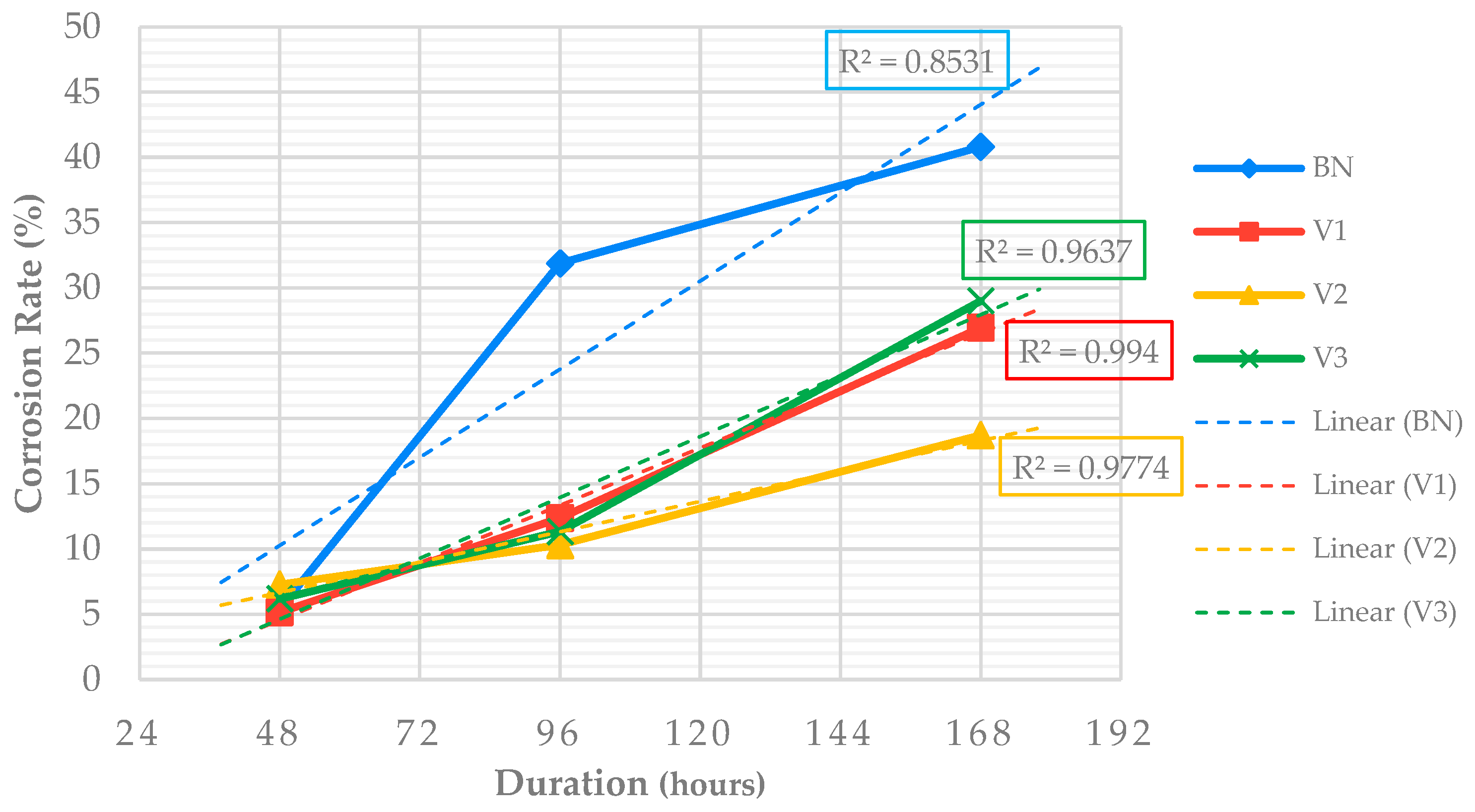
  • In the accelerated corrosion test, CFR-SHC has very good resistance to chloride ions compared to normal concrete, as shown by the always-lower current. From 48 h to 96 h, 0.75% CF had the lowest current, and it increased unsteadily until 168 h. However, in the final calculation, the actual corrosion rate of CF 0.5% was the smallest, 54% lower than normal concrete.
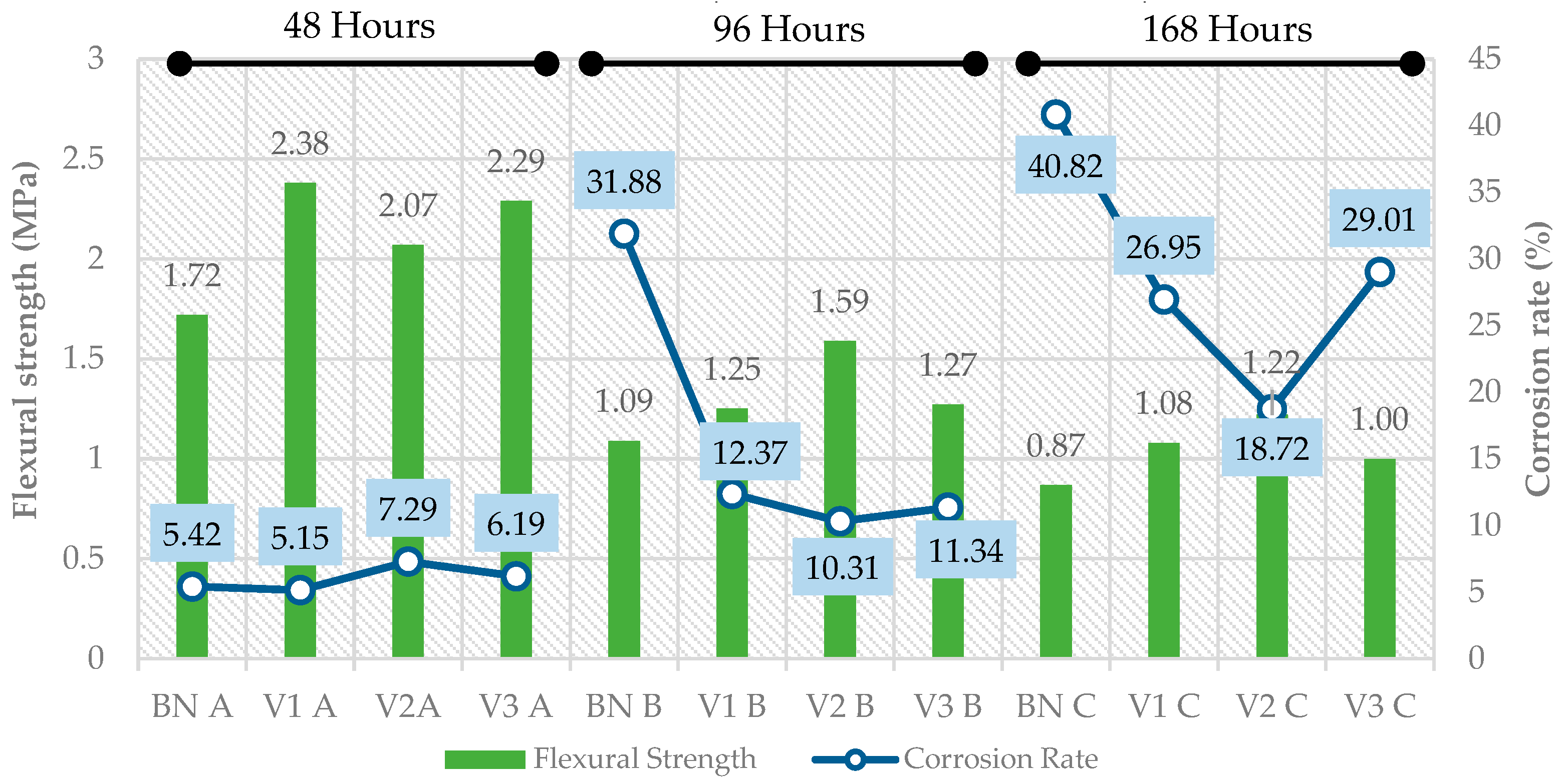
  • The flexural strength of the corroded CFR-SHC is inversely proportional to the corrosion rate. All CFR-SHCs obtained higher flexural strengths than normal concrete at higher corrosion rates. The 0.5% CF has a 40% higher flexural strength than normal corroded concrete.
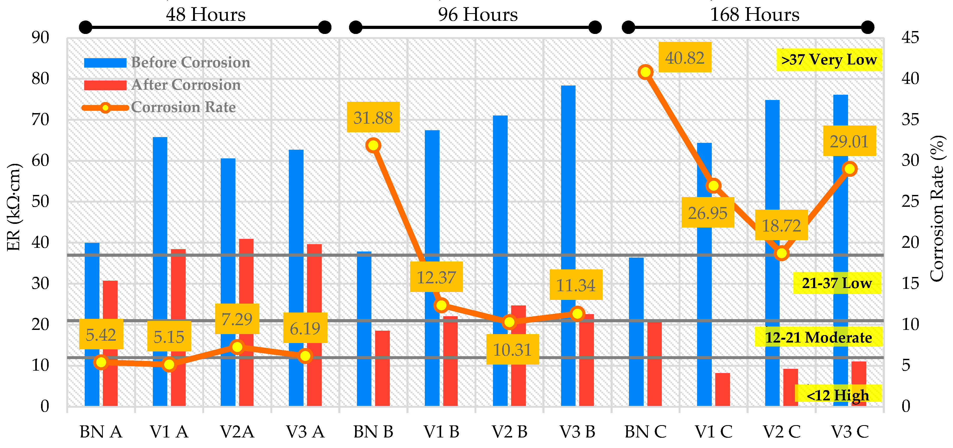
  • ER testing provides an evaluation of CFR-SHC due to the corrosion process, where ER is inversely proportional to the corrosion rate. Based on the ER results before corrosion, all specimens are still in the “very low” category for the corrosion rate. After corrosion, CF 0.75% obtains the largest ER value compared to other CFR-SHC mixes.
  • The IE test results deliver the peak frequency value, which is inversely proportional to the corrosion rate. Before being corroded, CFR-SHC had a higher frequency than normal concrete. At the beginning of corrosion, normal concrete was superior in frequency value, but at 0.25% CF weight corrosion, the frequency was 37% higher than normal concrete. Thus, the IE and ER methods in the tests conducted can effectively evaluate potentially corroded concrete and concrete that has been affected by corrosion.
Based on the above results, the improved mechanical properties and durability of CFR-SHC with 50 mm long coconut fiber, 0.5% fiber content, and the addition of 10% Bacillus subtilis best support its use in corrosion-tolerant concrete applications. However, other durability properties of CFR-SHC still need to be evaluated more extensively in the future due to the organic nature of coconut fibers.

Author Contributions

Conceptualization, A.Z.; methodology, A.Z.; software, K.M.; validation, A.Z.; formal analysis, K.M.; investigation, N.C.A.; resources, A.Z. and S.A.P.R.; data curation, S.A.P.R.; writing—original draft preparation, N.C.A.; writing—review and editing, A.Z. and S.A.P.R.; visualization, K.M.; supervision, A.Z.; project administration, K.M.; funding acquisition, A.Z. All authors have read and agreed to the published version of the manuscript.

Funding

This research was funded by Universitas Muhammadiyah Yogyakarta, grant number 50/R-LRI/XII/2023.

Institutional Review Board Statement

Not applicable.

Informed Consent Statement

Not applicable.

Data Availability Statement

The original contributions presented in the study are included in the article, further inquiries can be directed to the corresponding author.

Conflicts of Interest

The authors declare no conflicts of interest.

References

  1. Alomayri, T.; Yosri, A.M.; Ali, B.; Raza, S.S.; Yaqub, M.; Kurda, R.; Deifalla, A.F. The influence of coconut fibres and ground steel slag on strength and durability properties of recycled aggregate concrete: Sustainable design of fibre reinforced concrete. J. Mater. Res. Technol. 2023, 24, 10027–10039. [Google Scholar] [CrossRef]
  2. Kurda, R.; De Brito, J.; Silvestre, J.D. Combined Economic and Mechanical Performance Optimization of Recycled Aggregate Concrete with High Volume of Fly Ash. Appl. Sci. 2018, 8, 1189. [Google Scholar] [CrossRef]
  3. Kurda, R.; Silvestre, J.D.; de Brito, J. Life cycle assessment of concrete made with high volume of recycled concrete aggregates and fly ash. Resour. Conserv. Recycl. 2018, 139, 407–417. [Google Scholar] [CrossRef]
  4. Oh, D.-Y.; Noguchi, T.; Kitagaki, R.; Park, W.-J. CO2 emission reduction by reuse of building material waste in the Japanese cement industry. Renew. Sustain. Energy Rev. 2014, 38, 796–810. [Google Scholar] [CrossRef]
  5. Elahi, M.M.A.; Hossain, M.M.; Karim, M.R.; Zain, M.F.M.; Shearer, C. A review on alkali-activated binders: Materials composition and fresh properties of concrete. Constr. Build. Mater. 2020, 260, 119788. [Google Scholar] [CrossRef]
  6. Marcalikova, Z.; Racek, M.; Mateckova, P.; Cajka, R. Comparison of tensile strength fiber reinforced concrete with different types of fibers. Procedia Struct. Integr. 2020, 28, 950–956. [Google Scholar] [CrossRef]
  7. Sekar, A.; Kandasamy, G. Study on Durability Properties of Coconut Shell Concrete with Coconut Fiber. Buildings 2019, 9, 107. [Google Scholar] [CrossRef]
  8. Fediuk, R. Reducing Permeability of Fiber Concrete Using Composite Binders. Spéc. Top. Rev. Porous Media Int. J. 2018, 9, 79–89. [Google Scholar] [CrossRef]
  9. Althoey, F. Compressive strength reduction of cement pastes exposed to sodium chloride solutions: Secondary ettringite formation. Constr. Build. Mater. 2021, 299, 123965. [Google Scholar] [CrossRef]
  10. Faridul, H.K.M.; Haona, W.; Sakil, M.; Abu, T.M.; Cao, G. Wool functionalization through AgNPs: Coloration, antibacterial and wastewater treatment. Surf. Innov. 2021, 9, 25–36. [Google Scholar] [CrossRef]
  11. Ede, A.; Aina, A. Effects of Coconut Husk Fibre and Polypropylene Fibre on Fire Resistance of Concrete. Int. J. Eng. Sci. Manag. 2015, 5, 171–179. [Google Scholar]
  12. Khan, M.; Ali, M. Effect of super plasticizer on the properties of medium strength concrete prepared with coconut fiber. Constr. Build. Mater. 2018, 182, 703–715. [Google Scholar] [CrossRef]
  13. Ku, H.; Wang, H.; Pattarachaiyakoop, N.; Trada, M. A review on the tensile properties of natural fiber reinforced polymer composites. Compos. Part B Eng. 2011, 42, 856–873. [Google Scholar] [CrossRef]
  14. Venugopal, B.; Sambamurthy, V. Development and performance evaluation of coir pith ash as supplementary cementitious material in concrete. J. Eng. Technol. Sci. 2018, 50, 856–869. [Google Scholar] [CrossRef]
  15. Kušter Marić, M.; Ožbolt, J.; Balabanić, G. Reinforced concrete bridge exposed to extreme maritime environmental conditions and mechanical damage: Measurements and numerical simulation. Eng. Struct. 2020, 205, 110078. [Google Scholar] [CrossRef]
  16. Peng, C.; Wu, Q.; Shen, J.; Mo, R.; Xu, J. Numerical study on the effect of transverse crack self-healing on the corrosion rate of steel bar in concrete. J. Build. Eng. 2021, 41, 102767. [Google Scholar] [CrossRef]
  17. Zaki, A.; Wibowo, M.A.; Rosyidi, S.A.P.; Mahbubi, K. Corrosion Analysis of Concrete using Resistivity Method. In Proceedings of the 2023 International Workshop on Artificial Intelligence and Image Processing (IWAIIP), Yogyakarta, Indonesia, 1–2 December 2023; pp. 428–432. [Google Scholar] [CrossRef]
  18. Rahita, A.C.; Zaki, A. Corrosion Analysis on Reinforcing Steel in Concrete Using the Eddy Current Method. In Proceedings of the 2023 3rd International Conference on Electronic and Electrical Engineering and Intelligent System (ICE3IS), Yogyakarta, Indonesia, 9–10 August 2023; pp. 476–480. [Google Scholar] [CrossRef]
  19. Subeki, N.; Achmad Fauzan Hery, S.; Andi, F.; Gidiazalia, N. Crack Propagation Analysis of Fatigue Due to External Corrosion on the Construction of the Ferris Wheel in Alun-Alun Kota Batu. J. Adv. Res. Appl. Mech. 2023, 111, 62–73. [Google Scholar] [CrossRef]
  20. Jumaat, Z.; Kabir, M.; Obaydullah, M. A review of the repair of reinforced concrete beams. J. Appl. Sci. Res. 2006, 2, 317–326. [Google Scholar]
  21. Safiuddin, M.; Ihtheshaam, S.; Kareem, R.A.; Shalam. A study on self-healing concrete. Mater. Today Proc. 2022, 52, 1175–1181. [Google Scholar] [CrossRef]
  22. Zhang, F.; Ju, P.; Pan, M.; Zhang, D.; Huang, Y.; Li, G.; Li, X. Self-healing mechanisms in smart protective coatings: A review. Corros. Sci. 2018, 144, 74–88. [Google Scholar] [CrossRef]
  23. Nindhita, K.W.; Zaki, A.; Zeyad, A.M. Effect of Bacillus subtilis Bacteria on the mechanical properties of corroded self-healing concrete. Frat. Ed Integrita Strutt. 2024, 18, 140–158. [Google Scholar] [CrossRef]
  24. Abu Bakr, M.; Singh, B.K.; Deifalla, A.F.; Pandey, S.; Hussain, A.; Ragab, A.E.; Alvi, S.S.; Hasnain, S.M.M. Assessment of the mechanical and durability characteristics of bio-mineralized Bacillus subtilis self-healing concrete blended with hydrated lime and brick powder. Case Stud. Constr. Mater. 2023, 19, e02672. [Google Scholar] [CrossRef]
  25. Hammad, N.; Elnemr, A.; Shaaban, I.G. State-of-the-Art Report: The Self-Healing Capability of Alkali-Activated Slag (AAS) Concrete. Materials 2023, 16, 4394. [Google Scholar] [CrossRef] [PubMed]
  26. Nguyen, H.; Ghorbel, E. Effects of Bacillus subtilis on the compressive strength, porosity and rapid chloride permeability of concrete. Acad. J. Civ. Eng. 2019, 37, 223–228. [Google Scholar] [CrossRef]
  27. Ahmad, J.; Majdi, A.; Al-Fakih, A.; Deifalla, A.; Althoey, F.; Ouni, M.; El-Shorbagy, M. Mechanical and Durability Performance of Coconut Fiber Reinforced Concrete: A State-of-the-Art Review. Materials 2022, 15, 3601. [Google Scholar] [CrossRef] [PubMed]
  28. Vasagar, V.; Hassan, M.K.; Abdullah, A.M.; Karre, A.V.; Chen, B.; Kim, K.; Al-Qahtani, N.; Cai, T. Non-destructive techniques for corrosion detection: A review. Corros. Eng. Sci. Technol. 2024, 59, 56–85. [Google Scholar] [CrossRef]
  29. Ahmad, W.; Farooq, S.H.; Usman, M.; Khan, M.; Ahmad, A.; Aslam, F.; Yousef, R.A.; Abduljabbar, H.A.; Sufian, M. Effect of Coconut Fiber Length and Content on Properties of High Strength Concrete. Materials 2020, 13, 1075. [Google Scholar] [CrossRef]
  30. Nasser, H.; Van Steen, C.; Vandewalle, L.; Verstrynge, E. An experimental assessment of corrosion damage and bending capacity reduction of singly reinforced concrete beams subjected to accelerated corrosion. Constr. Build. Mater. 2021, 286, 122773. [Google Scholar] [CrossRef]
  31. Watanabe, T.; Nouchi, A.; Namerikawa, S.; Hashimoto, C. Evaluation of condition on replacing repaired concrete based on NDT and the Mahalanobis–Taguchi system. Front. Built Environ. 2023, 8, 956684. [Google Scholar] [CrossRef]
  32. Ahmad, J.; Manan, A.; Ali, A.; Khan, M.; Asim, M.; Zaid, O.; Taylor, G. A Study on Mechanical and Durability Aspects of Concrete Modified with Steel Fibers (SFs). Civ. Eng. Archit. 2020, 8, 814–823. [Google Scholar] [CrossRef]
  33. Sánchez Montero, J.; Saura Gómez, P.; Torres Martín, J.E.; Chinchón-Payá, S.; Rebolledo Ramos, N. Variation of Corrosion Rate, Vcorr, during the Carbonation-Induced Corrosion Propagation Period in Reinforced Concrete Elements. Materials 2024, 17, 101. [Google Scholar] [CrossRef]
  34. Sharkawi, A.M.; Seyam, A.M. Efficiency of accelerated techniques for assessing corrosion protection of blended cements. Mag. Concr. Res. 2019, 71, 637–646. [Google Scholar] [CrossRef]
  35. Robles, K.P.V.; Gucunski, N.; Kee, S.-H. Evaluation of steel corrosion-induced concrete damage using electrical resistivity measurements. Constr. Build. Mater. 2024, 411, 134512. [Google Scholar] [CrossRef]
  36. Su, T.; Wu, J.; Zou, Z.; Wang, Z.; Yuan, J.; Yang, G. Influence of environmental factors on resistivity of concrete with corroded steel bar. Eur. J. Environ. Civ. Eng. 2022, 26, 1229–1242. [Google Scholar] [CrossRef]
  37. Alhawat, M.; Khan, A.; Ashour, A. Evaluation of Steel Corrosion in Concrete Structures Using Impact-Echo Method. Adv. Mater. Res. 2020, 1158, 147–164. [Google Scholar] [CrossRef]
  38. Imperatore, S.; Benenato, A.; Spagnuolo, S.; Ferracuti, B.; Kioumarsi, M. Corrosion effects on the flexural performance of prestressed reinforced concrete beams. Constr. Build. Mater. 2024, 411, 134581. [Google Scholar] [CrossRef]
Figure 1. Materials: (a) Coconut fibers and (b) Bacillus subtilis bacteria.
Ndt 02 00013 g001
Figure 2. Fine grain gradation chart.
Ndt 02 00013 g002
Figure 3. Specimens: (a) beam and (b) cylinder.
Ndt 02 00013 g003
Figure 4. Illustration of the accelerated corrosion process.
Ndt 02 00013 g004
Figure 5. Mechanical test: (a) Compressive strength and (b) flexural strength.
Ndt 02 00013 g005
Figure 6. Illustration of resistivity testing.
Ndt 02 00013 g006
Figure 7. Illustration of Impact Echo testing.
Ndt 02 00013 g007
Figure 8. Results of concrete compressive strength test.
Ndt 02 00013 g008
Figure 9. Currents for each accelerated corrosion time: (a) 48 h, (b) 96 h, and (c) 168 h.
Ndt 02 00013 g009
Figure 10. Relationship between actual corrosion rate and duration of corrosion.
Ndt 02 00013 g010
Figure 11. Relationship between electrical resistivity and corrosion rate.
Ndt 02 00013 g011
Figure 12. Relationship between peak frequencies and corrosion rate.
Ndt 02 00013 g012
Figure 13. Relationship between flexural strength and corrosion rate.
Ndt 02 00013 g013
Figure 14. Relationship between resistivity and peak frequency values.
Ndt 02 00013 g014
Table 1. Test results of aggregate material.
TestFine AggregateCoarse AggregateUnit
Fine modulus 2.435--
Bulk specific gravity1.8372.642-
Saturated surface dry specific gravity2.2422.707-
Apparent specific gravity3.0942.826-
Water absorption2.1652.459%
Mud content1.001%
Abrasion-15.75%
Table 2. Mix Design of Concrete Specimens.
CodeWater
(liters)
Cement
(kilograms)
Fine Aggregate
(kilograms)
Coarse Agg.
(kilograms)
CF
(grams)
Bacillus S.
(milliliters)
BN 1.38 3.27 4.33 6.65 0 0
V11.38 3.27 4.33 6.65 1710
V21.383.264.336.653310
V31.38 3.27 4.33 6.65 5010
Disclaimer/Publisher’s Note: The statements, opinions and data contained in all publications are solely those of the individual author(s) and contributor(s) and not of MDPI and/or the editor(s). MDPI and/or the editor(s) disclaim responsibility for any injury to people or property resulting from any ideas, methods, instructions or products referred to in the content.

