Article

Concept Evaluation of Radical Short–Medium-Range Aircraft with Turbo-Electric Propulsion

1
Royal Netherlands Aerospace Centre NLR, Aerospace Vehicles Division, Collaborative Engineering Systems Department, Anthony Fokkerweg 2, 1059 CM Amsterdam, The Netherlands
2
ONERA—The French Aerospace Lab—Toulouse Center, 2, Avenue Edouard Belin, P.O. Box 74025, 31055 Toulouse CEDEX 4, France
*
Author to whom correspondence should be addressed.
Aerospace 2024, 11(6), 477; https://doi.org/10.3390/aerospace11060477
Submission received: 17 May 2024 / Revised: 13 June 2024 / Accepted: 14 June 2024 / Published: 17 June 2024

Abstract

:
Ambitious targets for the coming decades have been set for further reductions in aviation greenhouse gas emissions. Hybrid electric propulsion (HEP) concepts offer potential for the mitigation of these aviation emissions. To investigate this potential in an adequate level of detail, the European research project IMOTHEP (Investigation and Maturation of Technologies for Hybrid Electric Propulsion) explores key technologies for HEP in close relation with developments of aircraft missions and configuration. This paper presents conceptual-level design investigations on radical HEP aircraft configurations for short–medium-range (SMR) missions. In particular, a blended-wing-body (BWB) configuration with a turbo-electric powertrain and distributed electric propulsion is investigated using NLR’s aircraft evaluation tool MASS. For the aircraft and powertrain design, representative top-level aircraft requirements have been defined in IMOTHEP, and the reference aircraft for the assessment of potential benefits is based on the Airbus A320neo aircraft. The models and data developed in IMOTHEP and presented in this paper show that the turbo-electric BWB configuration has potential for reduced fuel consumption in comparison to the reference aircraft. But in comparison to advanced turbofan-powered BWB configurations, which have the same benefits of the BWB airframe and advanced technology assumptions, this potential is limited.

1. Introduction

The further reduction in greenhouse gas emissions is essential for aviation to accommodate the expected increase in air travel and at the same time to pursue its service to society and the environment. This calls for ambitious research and disruptive technology solutions, well beyond the continuous improvement of current aircraft technologies. Ample research has been recently reported on alternative, more electrified aircraft propulsion configurations, e.g., [1]. For instance, Salem et al. [2] present extensive analyses of the state of the art for hybrid electric propulsion, with focus on the technological development of hybrid electric powertrain components and on the conceptual development of transport aircraft proposed in the recent literature. Xie et al. [3], in their review, focus more on the design and energy management of hybrid aircraft and hybrid propulsion systems. Much of the work reported is related to regional aircraft applications. More specifically for SMR mission aircraft, for example, Jansen et al. [4] report on the design and evaluation of hybrid electric aircraft including distributed propulsion, where they investigate the aircraft-level feasibility and potential for a 2500-mile design range and 180-passenger capacity.
In the European Horizon 2020 project IMOTHEP (Investigation and Maturation of Technologies for Hybrid Electric Propulsion) [5], the exploration of key technologies for hybrid electric propulsion (HEP) is under investigation. This has to be addressed in close relation to developments in aircraft missions and configuration to derive relevant specifications for the investigation of electric components, such as the power needs and the operational constraints. This interrelation in IMOTHEP between integrated design at the aircraft vehicle level and the developments of key technologies for HEP components is illustrated in Figure 1.
As part of the IMOTHEP project’s activities on integrated vehicle design, conceptual-level design investigations are executed on various aircraft configurations. These configurations are targeted at missions that contribute significantly to unwanted aviation emissions, i.e., regional (REG) missions and short–medium-range (SMR) missions [6]. For both mission types, different types of hybrid electric aircraft and propulsion configurations are considered: conservative (CON) and radical (RAD). The conservative configurations include moderate technology developments without substantial design changes in the airframe. The radical configurations include more advanced technology developments in combination with unconventional airframe design. For the radical (RAD) configuration for short–medium-range (SMR) missions, in particular, a blended-wing-body (BWB) configuration with a turbo-electric (TE) powertrain and distributed electric propulsion (DEP) is investigated. This paper is focused on a TE- and DEP-powered SMR-RAD configuration. Strictly speaking, a TE powertrain is not an HEP architecture because it does not rely on multiple types of on-board energy sources for propulsion, i.e., typically kerosene and batteries. However, the TE powertrain does include the typical HEP sub-systems and components, like gas turbines, electric generators, motors, converters and inverters. Therefore, the TE powertrain does fit into the IMOTHEP project’s investigations on hybrid electric powertrain components.
The conceptual design investigations are based on representative top-level aircraft requirements (TLARs) that have been defined in the IMOTHEP project by the industrial airframers who are partnered with IMOTHEP. The reference aircraft for the SMR mission is based on the Airbus A320neo aircraft, slightly adapted to comply with the IMOTHEP TLARs for the SMR. The design objectives for the conceptual investigations are based on the IMOTHEP project targets. These project targets are expressed as criteria for emission reductions. These criteria are based on the ambition in IMOTHEP to achieve 10% more reduction than the targets that were set for 2035 in the European research program Clean Sky 2 (CS2) [7]. This means for IMOTHEP a target reduction of 40% in CO2 emissions for SMR aircraft in comparison with 2014 State of Art [5]. The CO2 emission is directly proportional to fuel consumption. Therefore, the target translates into a 40% fuel consumption reduction for typical-range missions.
This paper presents the aircraft-level design logic and requirements, as well as the synthesis of TE powertrain analysis results and their impact on the powertrain components’ sizing and overall energy performance. From these investigations, the main results on the fuel consumption and propulsive equipment sizing for the BWB airframe in combination with a powertrain based on a fully TE architecture are given. The fuel consumption results for the considered SMR-RAD configuration depend strongly on the estimates of the underlying electric component technologies for the considered time frame. Therefore, these underlying technologies and corresponding models are described in this paper as well, and the corresponding potential for fuel consumption reduction at the aircraft level is evaluated.

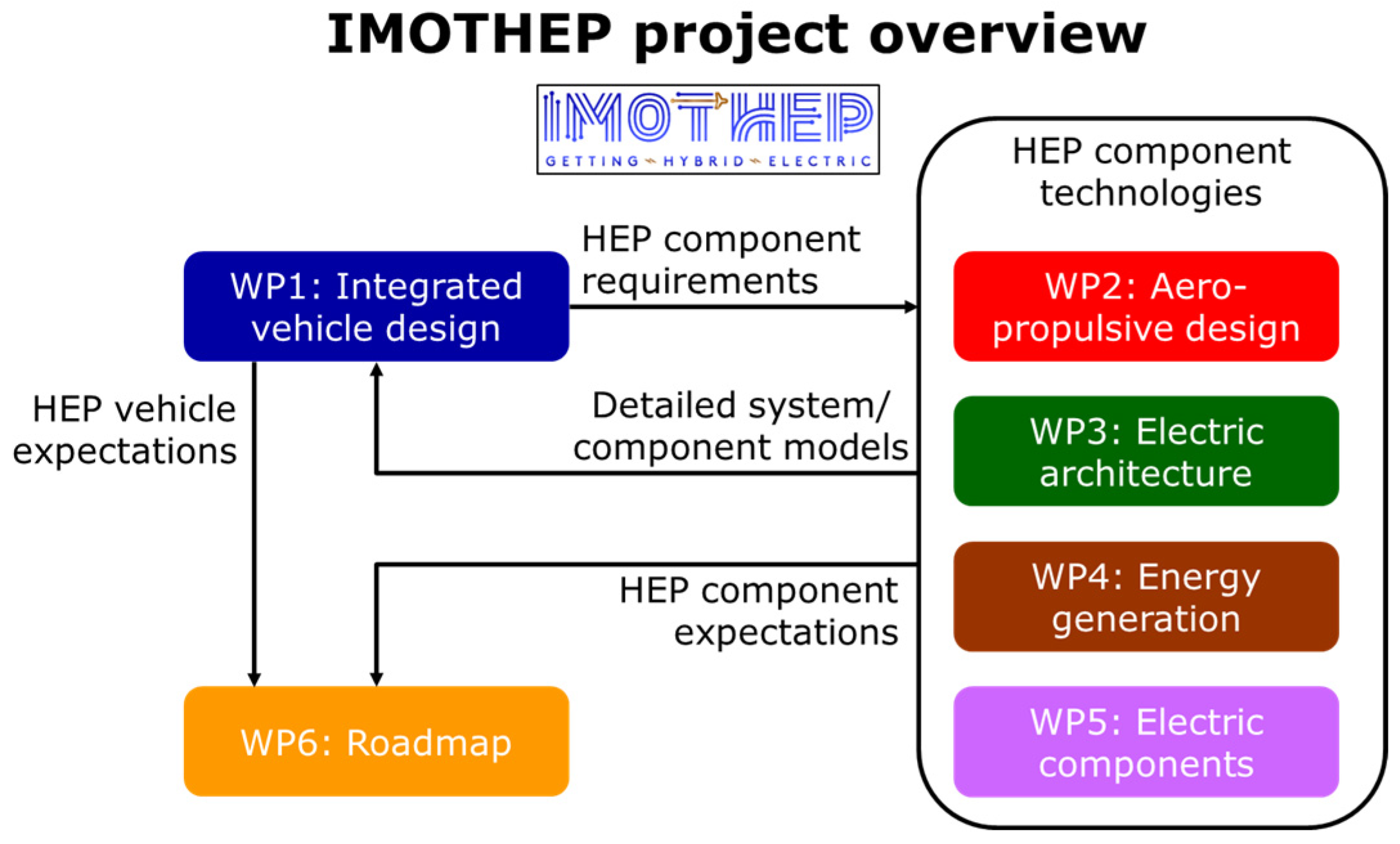
2. IMOTHEP Project Context

In the IMOTHEP project, the conceptual-level design evaluations for the SMR-RAD aircraft configuration are executed according to the overall IMOTHEP project’s design logic (Figure 2). The SMR-RAD aircraft design must comply with the TLARs that are defined in the project for SMR aircraft (Table 1). While complying with these TLARs, the design objectives for the SMR-RAD’s conceptual investigations are intended to fulfill the IMOTHEP project targets. The SMR-RAD’s design objectives are evaluated for the configuration’s entry into service (EIS) in 2035 (i.e., with 2035 technology assumptions) and compared to the reference aircraft (REF), which is a state-of-the-art aircraft based on A320neo but with 2014 technology assumptions and adapted to comply with IMOTHEP’s TLARs. In addition, the SMR-RAD’s design, which does include the potential benefits of the HEP powertrain, is also compared to the performance of SMR aircraft configurations with 2035 technology assumptions for conventional powertrains. These SMR aircraft configurations with conventional powertrains are represented by the so-called “Baseline” configuration (BAS) with a conventional tube-and-wing airframe and by a so-called “Non-hybrid-electric” configuration (0HEP) with a radical BWB airframe. The implementation of the IMOTHEP design logic is expressed in Figure 2 below.
The overall aircraft design methods and tools that are operational at NLR are used for the modeling, analyses and optimization of the aircraft and HEP components. Fast modeling methods are used to efficiently assess and compare the different aircraft configurations and propulsion options. In the IMOTHEP project, estimated technology assumptions for HEP components are consistently used in the various configuration studies. Specialized IMOTHEP partners from industry and research provide the specific inputs for the HEP components in the powertrain, like advanced or simplified models or estimates of the energetic performance and masses for the different components and assumptions of technology developments up to 2035. The technology assumptions for the different components and sub-systems are targeted at technology readiness level (TRL) 6 in 2035.
With this implementation of the IMOTHEP design logic (Figure 2), the SMR-RAD design and optimization studies are executed. The specifications from the airframers for the reference configurations (REF) and for the TLARs are top-level inputs for these design studies. The full list of TLARs is long and includes several detailed values for the operational requirements. The details are processed as design assumptions in Section 3. The main TLARs to be satisfied are summarized in the following, Table 1, where all the given values shall be considered lower limits.
Although the typical range is listed in Table 1, it is not a TLAR per se, but it is included here because it represents the range for which several additional requirements shall be fulfilled and for which the design objectives are evaluated. These requirements and objectives will be further explained below.

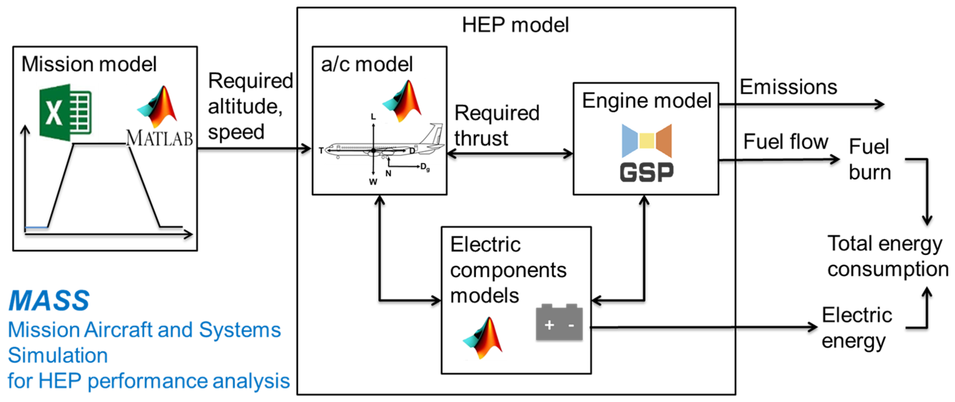
3. Modeling and Analysis Methods and Assumptions

The NLR investigations for the SMR configurations are carried out using the NLR tools for conceptual aircraft design and for mission evaluation MASS (Mission, Aircraft and Systems Simulation for HEP analysis) [8]. MASS includes models coming from various other tools, such as for flight mission modeling, aircraft modeling, electric components modeling and engine modeling (e.g., as provided by GSP, Gas Turbine Simulation Program [9], or comparable tools), and predicts fuel and energy consumption and emissions (Figure 3). MASS can be used for sizing of aircraft and powertrain components, but also for prediction of fuel and energy consumption and emissions for a given flight. Any propulsion powertrain architecture can be modeled in MASS, including conventional powertrains, parallel HEP, series HEP and TE architectures.
For the evaluations of each of the SMR configurations (SMR-REF, SMR-BAS, SMR-0HEP, SMR-RAD), the following top-level assumptions for aircraft and mission are used. These assumptions are combined with the main TLARs (Table 1) and with some additional requirements and specifications that are used in IMOTHEP. Some assumptions are slightly modified for some of the configurations, which will be explained when relevant. This leads to the following list of SMR design assumptions (SMR-DAS):
  • Payload:
    According to the TLARs, the design payload is 150 PAX@106 kg = 15,900 kg. The maximum payload is 20,000 kg = 189 PAX@106 kg, which is only used in some specific evaluations of the SMR configurations. A design payload of 150 PAX@106 kg = 15,900 kg will be used in all SMR evaluations.
  • Range:
    The typical-range mission at design payload is evaluated, in which the distance on the ground between take-off and landing is 800 NM (1482 km).
  • Atmosphere:
    In all the mission evaluations, the international standard atmosphere (ISA) [10] is assumed.
  • Take-off and landing:
    In all the mission evaluations, take-off and landing are assumed at airports on sea level. Landing is assumed with idle engines; reverse thrust in landing is not considered.
  • Taxi:
    The mission evaluation includes taxiing at airports, in which the taxi definitions given in CeRAS [11] are adopted: taxi-out is defined as 540 s of taxiing at a constant speed of 30 kts (15.4 m/s), yielding 8.33 km, and taxi-in is defined as 300 s of taxiing at a constant speed of 30 kts (15.4 m/s), yielding 4.63 km. The total taxi distance results in 12.96 km and will be used in all SMR evaluations.
  • Fuel burn:
    The actual mission fuel burn figure that is calculated in NLR’s mission evaluation is the “Block-off/Block-on fuel”, i.e., trip fuel + taxi fuel. Here, trip fuel is the fuel consumption from brake release on take-off at the departure aerodrome to the landing touchdown at the destination, and taxi fuel is the fuel consumption during taxi-out and taxi-in. The “Block-off/Block-on fuel” will be evaluated in all the SMR-RAD evaluations of NLR.
  • Reserve fuel:
    The definitions given in CeRAS for reserve fuel are as follows: reserve fuel is the sum of contingency fuel, alternate fuel, final reserve fuel, additional fuel and extra fuel, i.e., total fuel on board, minus trip fuel and taxi fuel. The reserve fuel needed for the SMR missions is calculated as follows: 5% contingency for the nominal mission fuel burn, go around, followed by 200 NM diversion at 15,000 ft altitude and 30 min hold at 1500 ft altitude.
  • Cruise:
    The definition given in CeRAS for SMR cruise conditions is a Mach 0.78 flight speed at an initial altitude of 35 kft (10.7 km). This altitude is applied to the REF and BAS configurations. The 0HEP and RAD configurations will fly at their optimal altitude (between 12 and 13 km).
  • Power offtake (PTO):
    The mechanical power offtake from the low-pressure turbine (LPT) shaft, for the power supply to non-propulsive on-board systems like pumps and generators, is taken into account. CeRAS applies a fixed PTO of 52 kW per engine. This value (104 kW in total) will be used in all the SMR-RAD evaluations of NLR.
  • Bleed offtake:
    Bleed air offtake from the low-pressure and high-pressure compressors (LPC, HPC), for the power supply to non-propulsive on-board systems like the ECS and IPS, are taken into account. CeRAS applies a fixed bleed offtake of 0.98 kg/s per engine. This value (1.96 kg/s in total) will be used in all the SMR-RAD evaluations of NLR.
  • Design range:
    A configuration is designed that is able to fulfil a mission with a range of 2750 NM (i.e., 5093 km) at the design payload (i.e., 15,900 kg).
  • Design mission:
    An Initial Cruise Altitude (ICA) of 33 kft (10.06 km) at ISA + 10 conditions is fulfilled: this is assumed to be fulfilled by a cruise altitude of 35 kft (10.7 km) under ISA conditions, which is used in all design missions, which is, given density, approximately equivalent to 33 kft (10.06 km) at ISA + 10.
  • Take-off field length (TOFL):
    Must be lower than 2200 m under ISA + 15 conditions: this is assumed to be fulfilled by the approximately equivalent TOFL of less than 2000 m under ISA conditions, which is used in all missions.
  • Climb time:
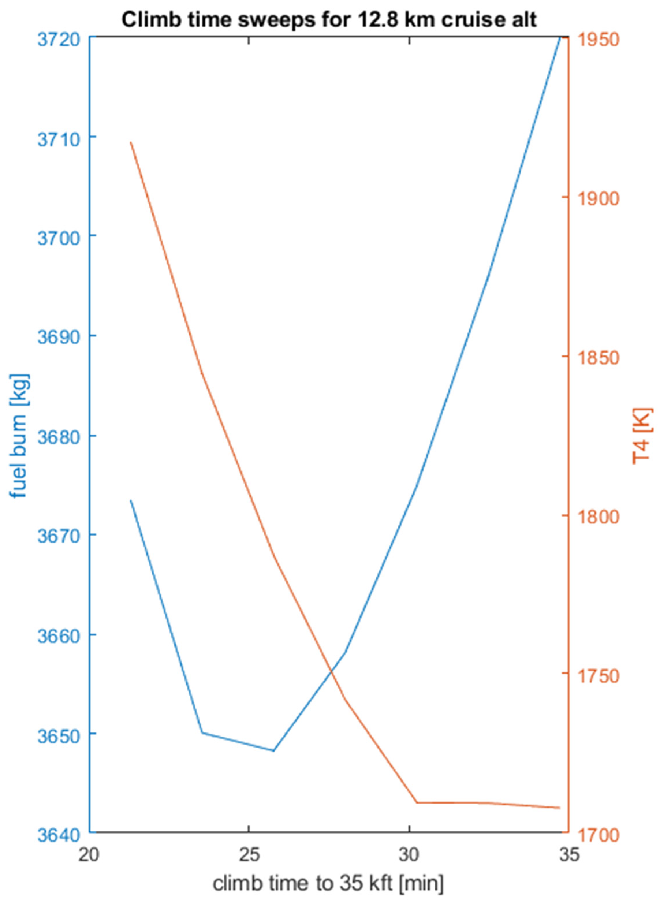
    Must be lower than 35 min from 1500 ft (0.46 km) to 33 kft (10.06 km) under ISA + 10 conditions: this is assumed to be fulfilled by an approximately equivalent climb time of less than 35 min from 1500 ft (0.46 km) to 35 kft (10.7 km) under ISA conditions, which is used in all missions.
  • Approach speed:
    Must be lower than 138 kts (71 m/s) in all missions.
  • Landing distance:
    Must be lower than 1800 m in all missions.
  • Typical range:
    800 NM (1482 km) under the default cruise conditions (800 NM @ Mach 0.78, 35 kft (10.7 km); CeRAS [11]).
  • Additional typical-range missions are defined:
    Default cruise conditions for max payload (20 t (20,000 kg) @ Mach 0.78, 35 kft (10.7 km)).
  • One engine inoperative (OEI):
    The SMR configurations are able to fulfil a mission with one engine inoperative at maximum take-off mass (MTOM), including take-off (TO) and climb until 15 kft (4.6 km) at a climb rate greater than 100 ft/min (0.51 m/s).
Besides the SMR-DAS, also, a number of SMR design optimization constraints (SMR-DOCs) are formulated. For all missions that comply with the SMR-DAS, several SMR-DOCs are checked for violations in order to assess the feasibility of the design. These SMR-DOCs are based on the following criteria: the maximum allowable values of CL (aircraft-level lift coefficient), Fn (aircraft-level net thrust force), N1 (turbofan engine low-pressure spool rotational speed) and TT4 (turbofan engine high-pressure turbine inlet temperature) shall not be exceeded. The allowable values for N1 and TT4 are based on or derived from the EASA Type certification sheet of the CFM-LEAP-1A engine [12]. The SMR-DOCs are determined as follows:
  • CL: The values of CL during the mission that are found from the MASS simulations should always remain below the maximum possible CL value. Because the current conceptual modeling does not include high-fidelity methods to calculate the maximum possible CL value, we estimate this value from the A320neo aircraft characteristics and mission specifications. This maximum possible CL value occurs in the low speed mission segments of take-off and landing.
    For rotation at take-off, the speed of A320neo shall be 150 kts (77.2 m/s) or more [13]. For straight-and-level flight at the MTOM (i.e., 79 t (79,000 kg) for the A320neo in REF), this leads to CL = (MTOM × g)/(Swing × 1/2ρv2) = 1.73. For the rotation, we assume that 10% extra lift is needed for a change in the flight path angle, yielding max(CL) = 1.9.
    For landing, we assume a final approach speed for A320neo of at least 131.5 kts (67.6 m/s) at maximum landing mass (MLM = 67,400 kg [13]. For straight-and-level flight, this leads to max(CL) = (MLM × g)/(Swing × 1/2ρv2) = 1.92. The SMR TLARs require an approach speed vapp < 138 kts (71 m/s), so vapp = 137 kts (70.5 m/s) is used in all missions.
    With these estimated max(CL) values, the variations in the wing area (i.e., the key design variable) shall be made such that the design constraint CL < max(CL) is always fulfilled.
    For the SMR-RAD and SMR-0HEP, separate max(CL) values are applied, related to the potential of the BWB aircraft; see Section 6 and Section 7.
  • Fn (net thrust force): The maximum take-off thrust of 120 kN per engine according to the CFM-LEAP-1A type certificate [12] shall never be exceeded.
  • N1 (low-pressure spool rotational speed): N1 shall remain below 101% of the maximum design speed according to the CFM-LEAP-1A type certificate [12].
  • TT4 (high pressure turbine inlet temperature): TT4 shall remain below 1850 K.
For the SMR-RAD case, the engine-related SMR-DOCs depend on the applied turboshaft engine design; see Section 7.

4. Design Evaluations for SMR-REF

For the design evaluations of the SMR-REF configuration, the aircraft model of the A320neo and the engine model of the CFM-LEAP-1A turbofan are based on existing models available at NLR [8]. But this SMR-REF aircraft model is re-designed to comply with the IMOTHEP TLARs. The re-design of the SMR-REF aircraft is simplified to one basic design variable, wing area (Sw), which is determined such that the mission fuel is minimized and the aircraft complies with the SMR-DAS and SMR-DOCs. The details of these analyses are reported in [14], but key results and conclusions from the evaluations of the SMR-REF configuration are the following:
  • For a SMR-REF configuration that is feasible for the design range of 2750 NM@35 kft (5093 [email protected] km), the wing area cannot be reduced below 123 m2. The critical case is the SMR-DAS failure case “OEI at TO with MTOM”. For this SMR-REF configuration, the total mission fuel burn for the typical 800 NM mission is 4838 kg.
This fuel burn value is slightly lower than in [14] due to slightly different assumptions on speed and altitude in the mission profile.

5. Design Evaluations for SMR-BAS

For the evaluations of the SMR-BAS configuration, also, the aircraft model of the A320neo and the engine model of the CFM-LEAP-1A turbofan are based on the existing models available at NLR. The SMR-DAS and SMR-DOCs as described above are also used for the SMR-BAS evaluations.

2035 Technology Assumptions

The SMR-BAS models of the aircraft and engine are first updated for 2035 aircraft EIS technologies and then re-designed for the IMOTHEP TLARs. This re-design of the SMR-BAS aircraft is also simplified to a single basic design variable: wing area. The 2035 technologies are based on the assumptions described in Table 2.
These 2035 technology assumptions were implemented in the SMR-BAS models in the following way:
  • 2035 in comparison to 2014 turbofan engine assumptions:
    A thrust-specific fuel consumption (TSFC) reduction of 7% in comparison to the 2014 CFM-LEAP-1A engine has been implemented in the SMR-BAS models, accounting mainly for the expected fan propulsive efficiency improvements (In [14], a TSFC reduction of 10% was accounted for. However, new discussions with engine specialists in the IMOTHEP project resulted in a lower reduction of 7%).
    Thrust-over-weight ratio (T/W) +3.7% in comparison to A320neo: Apply a 3.7% reduction in engine mass, i.e., ~0.037 × 3000 kg = 111 kg per engine, so a 222 kg decreased mOE has been implemented in the SMR-BAS models.
    Wetted area to be adjusted: Because UHBR engines have a larger fan diameter but a shorter length, the change in the nacelle wetted area is a bit speculative. Therefore, no change in the nacelle wetted area has been implemented in the SMR-BAS models.
  • 2035 in comparison to 2014 component mass assumptions:
    Wing mass −10%: i.e., ~0.1 × 8800 kg = an 880 kg decreased mOE has been implemented in the SMR-BAS models.
    Fuselage mass −5%: ~0.05 × 8800 kg = a 440 kg decreased mOE has been implemented in the SMR-BAS models.
    Landing gear mass −15%: ~0.15 × 2200 kg = a 330 kg decreased mOE has been implemented in the SMR-BAS models.
    Pylons mass −5%: ~0.05 × 650 kg = 32.5 kg per pylon, so a 65 kg decreased mOE has been implemented in the SMR-BAS models.
    Furniture mass −25%: ~0.25 × 2440 kg = a 610 kg decreased mOE has been implemented in the SMR-BAS models.
  • 2035 in comparison to 2014 aerodynamics assumptions:
    +3.3% on L/D (lift over drag): A 3% reduction applied to CD has been implemented in the SMR-BAS models.
    −5% on CD0 (zero-lift drag coefficient) of the wing: A decrease in CD0 by 5% has been implemented in the SMR-BAS models.
    −50% on CDw (wave drag coefficient): A decrease in CDw by 50% has been implemented in the SMR-BAS models.
    −10% on CDi (induced drag coefficient): A decrease in CDi by 10% has been implemented in the SMR-BAS models.
  • The 2035 technology assumptions yield a total mass reduction at the aircraft level (i.e., total decreased mOE) of 2547 kg.
Just like for the SMR-REF, the SMR-BAS configuration is evaluated at the design range of 2750 NM (5093 km) (see the TLARs in Table 1). A potential re-sizing of the wing area is evaluated by checking the design constraints (SMR-DOCs) described above for the various missions, as prescribed by the TLARs.
It is found that for SMR-BAS, the typical mission results do not depend on the design range requirement because the maximum payload requirement is the sizing condition. The key results and conclusions from the evaluations of the SMR-BAS configuration are the following:
  • For the SMR-BAS configuration, the wing area can be reduced to 107 m2. The critical case for this SMR-BAS configuration with a reduced wing area of 107 m2 is the mission evaluation for the SMR-DAS of the maximum payload (20,000 kg). For this SMR-BAS configuration, the total mission fuel burn for a typical mission is 3927 kg.
This fuel burn value for SMR-BAS is slightly higher than in [14] due to slightly different assumptions on speed and altitude in the mission profile and the lower reduction in TSFC (Table 2).

6. Design Evaluations for SMR-0HEP

For the evaluations of the SMR-0HEP configuration, a blended-wing-body (BWB) aircraft concept was adopted from an earlier study at ONERA [16]; see Figure 4. In this study, comparable TLARs and EIS 2035 technology assumptions were used as in the IMOTHEP SMR evaluations. In the SMR-0HEP evaluations, the inputs for the BWB aircraft definition are taken from ONERA’s BWB concept study [16], which investigates the optimized BWB aircraft concept with conventional propulsion using two CFM-LEAP-1A turbofan engines and 2035 EIS technology assumptions. Because the TLARs that were used in ONERA’s BWB concept study are not exactly the same as the TLARs in IMOTHEP, the SMR-0HEP design evaluations may yield constraints that are violated. Therefore, in the SMR-0HEP evaluations, similar design variations are considered to those for the REF and BAS configurations.
The main input parameters for the evaluations with NLR’s MASS tool are the global aircraft sizing data like shape and global dimensions, masses and drag polars. The BWB shape and global dimensions are adopted from [16] and are illustrated in Figure 4. This BWB geometry accounts for a 150 PAX cabin layout, and its projected wing area is 268.6 m2. The mOE of the BWB is also adopted from [16]: mOE = 36,042 kg.

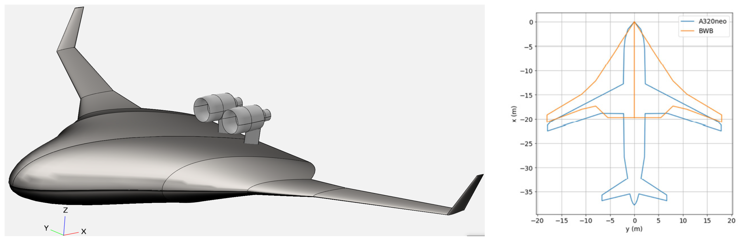
6.1. SMR-0HEP Aerodynamic Characterization

The drag polars for the BWB clean configuration without engines have been evaluated using Reynolds-averaged Navier–Stokes (RANS) analyses. The computational fluid dynamics (CFD) software ENSOLV [17] of NLR has been used for the calculations for the relevant flight conditions. These conditions comprise a number of speed–altitude combinations that are representative of the considered mission (Figure 5). These conditions are expressed by the Mach number and the altitude in the ISA. The resulting drag polars are depicted below in Figure 5. The drag polar data comprise the aircraft-level lift coefficient (CL) and drag coefficient (CD) versus the angle of attack (α). The lift and drag coefficients have been evaluated for sequences of α. Data above certain maximum values of α have been excluded from further processing. These maximum values of α are indicated by the gray circles in Figure 5. The maximum CL values that can be achieved with the BWB clean configuration without engines for take-off and landing conditions at sea level are about 0.66. It is assumed in this study that high-lift systems may well increase the maximum CL values as needed, but detailed quantification of high-lift effects on max(CL) is currently beyond the scope of this study. Furthermore, the BWB clean body has been aerodynamically designed for optimal cruise operation at around Mach 0.78 at a 41 kft (12.6 km) altitude and with a CL value of about 0.27. Therefore, this cruise condition is considered for the design range and the typical-range missions of the SMR-0HEP configuration.
For an efficient incorporation of the drag polars into the MASS tool, a map of CD as a function of CL and the Mach number is generated using surrogate modeling methods. Polynomial methods of various orders and artificial neural networks (ANNs) with various numbers of hidden nodes are evaluated. A feedforward ANN [18] with nine hidden nodes is found to give the most accurate representation of the drag polar data and is therefore used in the MASS evaluations. On top of this drag polar representation of the BWB clean configuration, extra parasite drag contributions are added for the two turbofan engines. A fixed value of 11.9 drag counts (CDpar = 0.00119) was estimated in [16] and has been used here too.

6.2. SMR-0HEP Design Evaluations

The SMR-0HEP configuration represents the radical airframe design of the BWB, but with conventional turbofan propulsion. Just like for SMR-BAS, also here, the GSP-based implementation of the CFM-LEAP-1A in MASS with a 7% TSFC reduction due to the 2035 technology specifications is used as the turbofan model. Just like for SMR-BAS, the SMR-0HEP configuration is also considered for the design range of 2750 NM (5093 km) (see the TLARs in Table 1). In a previous IMOTHEP iteration [14], a re-sizing of the wing area was evaluated by checking the design constraints described above for the various missions as prescribed by the TLARs. This resulted in a total wing area increase of 7%. During updated aerodynamic analyses with this BWB configuration, it was found that high-lift surfaces can be considered feasible, and as such, the wing area does not need to be increased.
It is found that for SMR-0HEP, the typical mission results do not depend on the design range requirements because the maximum payload requirement is the sizing condition. The key results and conclusions from the evaluations of the SMR-0HEP configuration are the following:
  • Updated: For the SMR-0HEP configuration with an unchanged wing area of 268.6 m2, which is feasible for the design range of 2750 NM@41 kft (5093 [email protected] km), the maximum CL required during landing for a maximum-payload (20,000 kg) mission is max(CL) = 0.70. It is assumed that this max(CL) value can be achieved with the high-lift systems installed in the SMR-0HEP configuration. The critical case is mission evaluation for the SMR-DAS for the maximum payload (20,000 kg). For this SMR-0HEP configuration, the total mission fuel burn for a typical mission is 3581 kg.
This fuel burn value for SMR-0HEP is slightly lower than in [14] because the wing area was not increased, resulting in a lower empty weight. Furthermore, the cruise altitude was altered (to 13.2 km) to achieve the maximum lift over drag and minimum fuel consumption.

7. Design Evaluations for SMR-RAD

For the SMR-RAD configuration, the same BWB airframe and underlying assumptions are used as for the SMR-0HEP configuration. This is because a sensible comparison between SMR-RAD and SMR-0HEP must be made. For SMR-RAD, only the propulsion system is changed from a turbofan (i.e., the two CFM-LEAP-1A engines with 2035 EIS technology assumptions for 0HEP) to a HEP architecture. Of course, this change from a turbofan to an HEP powertrain implies changes in the mass and energetic efficiencies of the propulsion system, which will be addressed in this section.

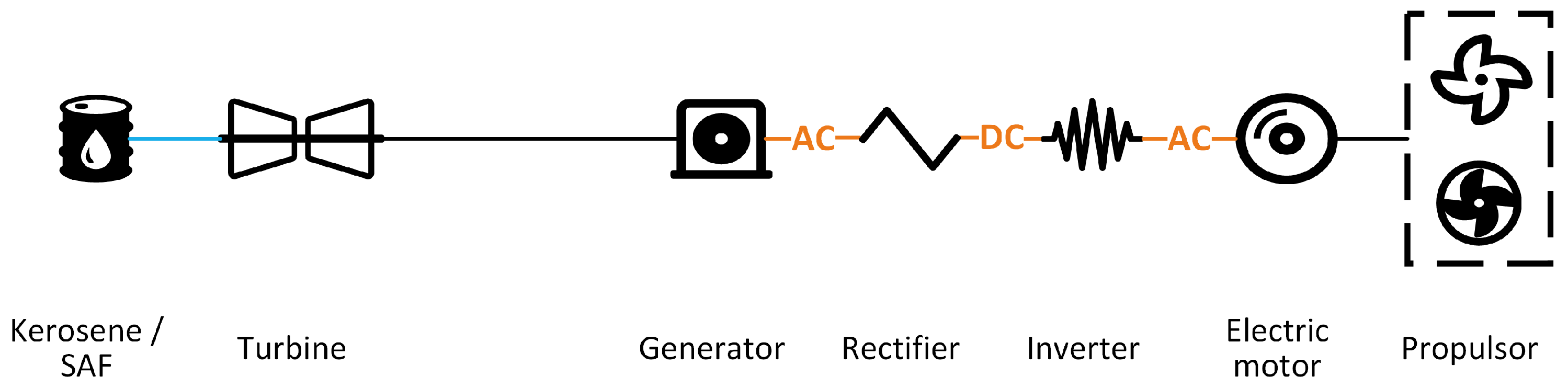
7.1. Turbo-Electric Architecture for SMR-RAD

HEP can be implemented in the propulsion powertrain in various ways. Common HEP architectures for aircraft have been proposed, for example, by NASA [19], where the series hybrid architecture, parallel hybrid architecture, all the electric architecture and turbo-electric architecture are distinguished. As an illustration of a common HEP architecture, Figure 6 shows a schematic representation of a kerosene-powered turbo-electric powertrain configuration. Various other HEP architectures (parallel hybrid, etc. [16]) have been evaluated for the SMR-RAD configuration and were previously reported [14]. It was found that the best potential for fuel efficiency clearly exists for the turbo-electric architecture. Therefore, this paper focuses on further design evaluation of this configuration for the SMR-RAD aircraft.
As indicated in Figure 6, the turbo-electric architecture comprises a turboshaft combustion engine that powers an electric generator. This generator powers electric motors that drive one or multiple fans. The turbo-electric architecture has potential for an energy-efficient architecture because it does allow for a large fan area through distributed propulsion but it does not have the burden of an excessive battery mass. In the IMOTHEP project, a turbo-electric configuration with eight semi-embedded ducted fans (DFs), each with a 1.89 m fan diameter, was analyzed in detail, both at the powertrain component level and at the aircraft level. Several enhanced component models and improved estimates have been integrated into the SMR-RAD system model and will be presented in the next sections.

7.2. Aerodynamic Effects for SMR-RAD

The turbo-electric architecture for SMR-RAD is implemented using eight ducted fans that are all installed in the rear center body of the BWB airframe. Two turbo-generators (providing the electric power) are installed under the (inboard) outer wings. The aerodynamic effects of this propulsion installation are estimated as simple parasite drag contributions. On top of the drag polar representation of the BWB clean configuration (Figure 4) as described for SMR-0HEP, extra parasite drag contributions can be expected for the turbo-generators and ducted fans of SMR-RAD. For the turbo-generators, the parasite drag contribution in cruise conditions is assumed to be compensated for by the small residual thrust that the turboshaft engines also provide, which is estimated at about 0.6 kN per engine in cruise conditions. For the eight semi-embedded ducted fans with a diameter of 1.89 m, the parasite drag contribution in cruise conditions was estimated at 20 drag counts (CDpar = 0.0020). This corresponds to an approximately 17% increase in drag compared to the clean BWB configuration. Because of the semi-embedded installation of these ducted fans, there is a boundary-layer ingestion (BLI) benefit, which, in this study, is accounted for in the overall drag of the SMR-RAD aircraft. From low-fidelity analyses [20], it was concluded that a 2% reduction in cruise thrust could be achieved due to BLI. In the case of the SMR-RAD mission evaluations, this is included as a 2% reduction in the aircraft-level drag coefficient. Therefore, the net drag increase due to propulsion installation effects is estimated at about 15% in cruise.

7.3. Propulsion System Mass Estimations

The mass changes due to the update from the turbofan propulsion of the 0HEP configuration to the turbo-electric propulsion of the RAD configuration are partly estimated and partly result from the propulsion system sizing that is calculated using NLR’s MASS tool. An overview of the components considered and their mass estimates is given in Table 3. For the considered SMR-RAD turbo-electric configuration, the two turbofan engines are replaced with turboshaft engines and electric generators for power generation and eight ducted electric fans for thrust generation. Each of these turboshaft engines and ducted fans requires a pylon (or an internal mounting structure) and nacelle for proper installation on the BWB airframe. For the semi-embedded ducted fans, no additional pylon mass was accounted for. The internal mounting structure was assumed to be covered by the aircraft’s structural weight. The location of the fans is currently assumed to be the rear center body of the BWB, symmetric in its center–vertical symmetry plane. The two turbo-generators (turboshaft engines and generators) are mounted under the (inboard) outer wings, as illustrated in Figure 7. The location of the fans may yield benefits in terms of noise shielding and the BLI for the fans but also may have disadvantages in terms of maintenance, weight and balance and thrust vector alignment. The details on the noise shielding and BLI aspects are beyond the scope of this paper. This paper is mainly focused on the conceptual design and sizing of the propulsion components and the TE powertrain.
It must be noted that in the table for SMR-RAD, the pylon mass of 1250 kg is divided over two turbo-generators and eight ducted fans, but because the semi-embedded ducted fans are assumed to be mounted directly onto the airframe, their pylon mass is assumed to be 0 kg, and for the pylon mass of the two turbo-generators, 2 × 125 kg is used.
The mass estimation of the turbofan is based on actual data on the CFM-LEAP-1A engine, with a wet engine mass of 2990 kg [12]. For A320neo, the nacelle and auxiliary systems have a mass of about 1200 kg [13], and the pylon mass is about 625 kg [14]. For 0HEP, we take into account the mass reductions due to the 2035 EIS technology assumptions (similar to BAS, as given in Table 2, Section 5), yielding approximately 2879 kg for the engine and 625 kg for the pylon.
For the SMR-RAD propulsion system, the masses of the turboshaft engine and the power turbine are estimated at about 700 kg and 300 kg, respectively. It must be noted that the power turbine is a dedicated turbine that drives the electric generator; the electric generator is a separate component, for which separate mass estimation is undertaken. Furthermore, a 25 kg lubrication oil mass was assumed.
The masses of the nacelle and pylon components are estimated in the following way for the SMR-RAD configuration. The pylon mass is dominated by its structural sizing for the transfer of thrust forces. Because the total thrust force at the aircraft level for SMR-RAD is not very different from that of SMR-0HEP, the total mass of all the pylons on SMR-RAD is assumed to be equal to the total mass of all the pylons on SMR-0HEP, i.e., 1250 kg. The nacelle mass of a ducted electric fan, of the same size as the CFM-LEAP-1A nacelle, with a fan diameter of about 2 m, is assumed to be one-third of the mass of the CFM-LEAP-1A nacelle, i.e., 400 kg. This is because of the much simpler construction and system installation for the ducted electric fan. For example, the thrust reverser, with a mass of about 400 kg for one CFM-LEAP-1A nacelle, is not needed in the ducted fans because of the assumed reversed rotation capability of the electric fans. The ducted electric fans have been sized on the basis of the fan area. The nacelle mass is assumed to be proportional to the nacelle wetted area and therefore also proportional to the ducted fan diameter because the nacelle length is assumed to be constant. Consequently, for a ducted electric fan nacelle equivalent in size to the CFM-LEAP-1A nacelle, the diameter-specific nacelle mass is 400 kg divided by the 2 m fan diameter, yielding 200 kg/m. Taking into account that the ducted fans are semi-embedded into the center wing, this mass is assumed to be further reduced by 1/3.
For simplicity, the same structures for the pylon and nacelle are assumed for the ducted fans and for the turbo-generators (i.e., the assembly of turboshaft engine, power turbine and electric generator). For the SMR-RAD pylons, this implies that the total pylon mass at the aircraft level, i.e., 1250 kg, comprises n + 2 pylons for n ducted fans and 2 turbo-generators. So, for the 8 ducted fans, the pylon mass is 1250 kg for 8 + 2 = 10 pylons, i.e., 125 kg per pylon. For the SMR-RAD nacelles, for the ducted fans and turbo-generators, the mass equals the nacelle diameter times the diameter-specific nacelle mass. The turbo-generators are assumed to have a nacelle of a 1 m diameter. So, for example, for 8 ducted fans of a 1.89 m diameter, the nacelle mass is 200 kg/m times 1.89 m, and times 2/3, this is 252 kg, and for the turbo-generators of a 1 m diameter, the nacelle mass is 200 kg/m, which times 1.0 m is 200 kg, so the total nacelle mass at the aircraft level is 8 × 252 + 2 × 200 = 2416 kg.
The mass of the fan rotor (i.e., 18 carbon composite blades and a metallic rotor hub) of the CFM-LEAP-1A is estimated at 100 kg for a fan area of about 3.1 m2. The fan rotor of the ducted electric fan is also assumed to consist of 18 composite fan blades and a metallic rotor hub, at a similar areal mass of about 32 kg per m2 fan area. The mass estimation of the electric powertrain components, like the generators, power electronics and electric motors, is handled internally using the MASS tool in relation to the power requirements during the mission.

7.4. Energetic Efficiencies of the Propulsion System

The energetic efficiencies of the CFM-LEAP-1A turbofan engines in the SMR-0HEP configuration are incorporated in the GSP engine model [21]. For the SMR-RAD’s turbo-electric propulsion system, the energetic efficiencies of the powertrain components are incorporated into the turbo-electric component models. The main turbo-electric components are the turboshaft engine with a power turbine, the electric generator with an AC-DC converter, the electric distribution system with power cables, switches and buses, the electric motors with inverters and power electronics and the ducted fans. For each of these main components, more or less elaborate modeling approaches are followed, as illustrated in Figure 8.

7.5. Electric Components Models

The electric components in the powertrain comprise the electric generator (EG) with an AC-DC converter, the electric distribution system and the electric propulsion units (EPUs) with DC-AC inverters (third box from the left in Figure 8).
The conceptual design, sizing and performance of these electric components was investigated in detail by the subject matter experts in IMOTHEP [21], taking into account the anticipated 2035 technology levels. This resulted in component efficiencies and specific power values that could be used for the full powertrain sizing of SMR-RAD. The estimated specific power values and efficiency values for the EG, electric motor (EM), converter (AC-DC) and inverter (DC-AC) are listed in Table 4.
The energetic losses in the electric components cause undesired heat generation. This heat has to be actively evacuated using a cooling system. The equipment sizing of this required cooling system (CS) is also included in a simplified way. Currently, the overall specific power of the CS has been estimated at 1.18 kW/kg, and this is applied to estimate the weight of the CS. This weight is derived as follows: the maximum losses per component in the turbo-electric powertrain are calculated using the components’ efficiencies (components heat generation power factor = 1 − efficiency). The heat generation power of all the components is then divided by the specific power of the CS to estimate the overall CS weight.
An electric architecture (see Figure 9) has been defined in IMOTHEP for SMR-RAD, which is based on maximum redundancy and fault mitigation. The architecture layout for SMR-RAD has been developed in IMOTHEP under the assumption that each of the eight electric propulsion units (EPUs) and ducted fans produces equal thrust and power and has the same RPM. As a result, this electric architecture includes four propulsion buses, four generators, each connected to a rectifier and distribution bus, and two turboshaft engines.
The bus masses—including the electric distribution units, switches and circuit breakers—are sized using a specific power value of 20 kW/kg, applied per bus type.
For the cable sizing, estimations of the length of various cable types were provided, as well as the specific cable weights (per length unit). The values have been processed into Table 5 below to derive the total cable mass in the context of SMR-RAD, corresponding to the electric architecture in Figure 9. This results in a total cable mass of 246 kg. The cable insulation materials are included in the specific cable mass. The cable losses are ignored, as the efficiencies are larger than 99.9%.

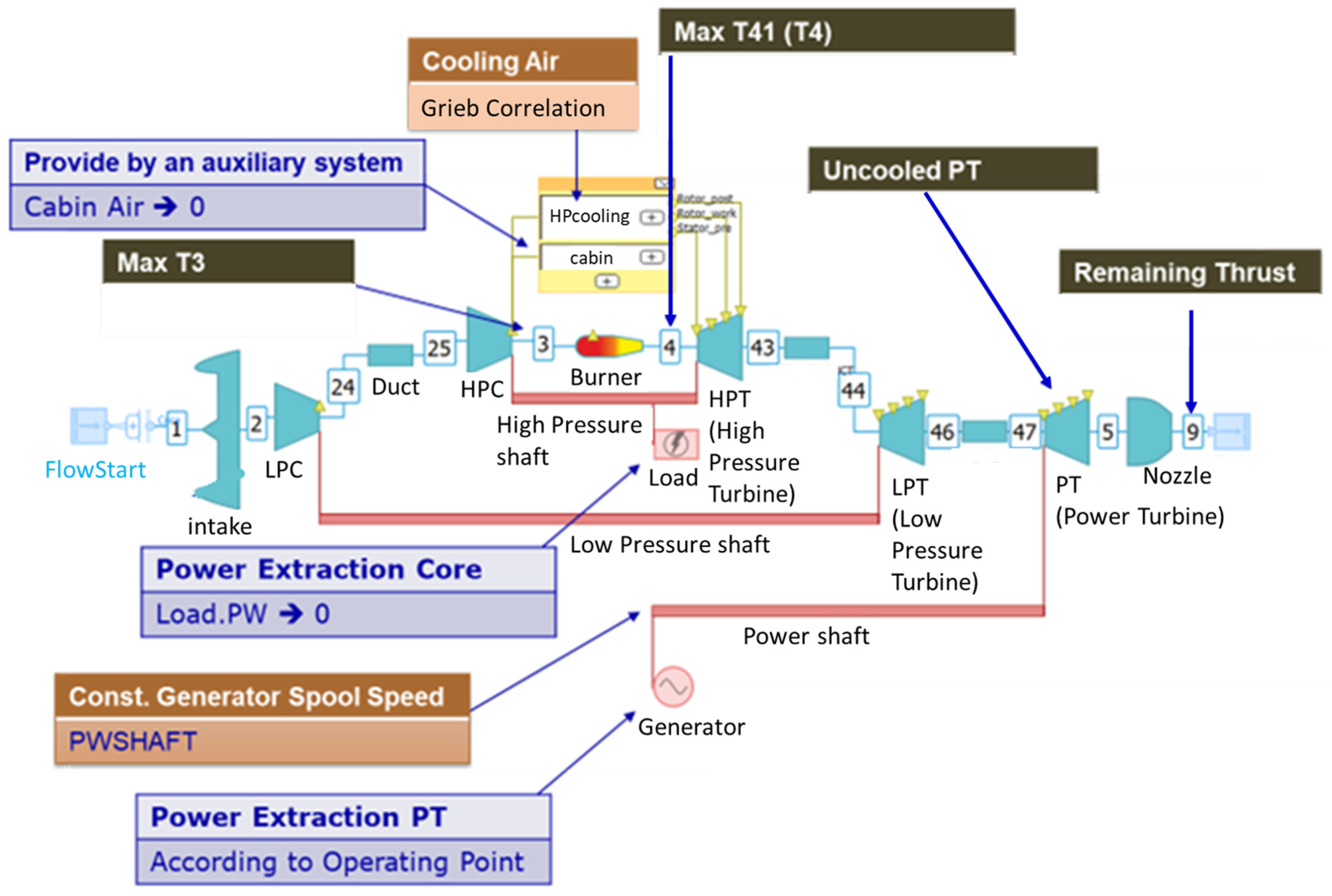
7.6. Turbo-Generator Model

The turboshaft engine (on the left side of Figure 8) is included as a gas turbine cycle model, developed using DLR’s GTLab environment [23] that covers different modules and methods for thermodynamic, aerodynamic and mechanical calculation of the main gas turbine sub-systems (compressor, combustion, turbines). This is illustrated in Figure 10.
The turboshaft model that was developed is dedicated to SMR-RAD’s required approximate power levels. It was designed for a maximum shaft power of 11.4 MW per engine (at take-off). The gas turbine cycle model predicts the fuel mass flow ( m ˙ f u e l ) and the high-pressure turbine (HPT) inlet temperature ( T T 4 ) as a function of the required power ( P s h a f t , T S ), altitude ( h ) and Mach number ( M ) during the mission. The constraint for this turboshaft engine is only on the HPT inlet temperature: T T 4 < 1850 K. The turboshaft engine drives a specific power turbine that is dedicated to powering the electric generator through a direct drive shaft. The assembly of the turboshaft, power turbine and electric generator constitutes the complete turbo-generator component. The SMR-RAD powertrain contains two of such turbo-generators in parallel for redundancy.
The SMR-RAD turboshaft engine features a typical cruise power-specific fuel consumption (PSFC) of 0.166 kg/kWh. It should be noted that the turboshaft engine is specifically designed only for shaft power offtake. When bleed offtake is also applied—for non-propulsive on-board systems such as the environmental control system (ECS)—a large performance penalty would follow. A bleed offtake of 1 kg/s per engine—which corresponds approximately to the 0.98 kg/s bleed offtake that is assumed to be required for SMRs [11]—results in a 10% increase in the PSFC. It is more efficient to avoid bleed offtake and also extract all the power for the non-propulsive systems from the turboshaft’s power turbine shaft, which is connected to the electric generator. This results in a so-called More Electric Aircraft (MEA) architecture for SMR-RAD, which avoids the bleed air extraction. Consequently, the non-propulsive pneumatic systems that are the consumers of the bleed air, in particular the ice protection system (IPS) and environmental control system (ECS), must also be replaced with non-pneumatic systems. The pneumatic IPS can be replaced with electric heating systems, and the bleed air supply to the pneumatic ECS can be replaced with electric air compressors. Besides the pneumatic systems, the hydraulic systems, like flight control and landing gear actuators, can also be replaced with electric alternatives. The changes in the system masses and the power requirements for such MEA architecture for an A320neo-category aircraft have previously been investigated [24], and the following values are adopted for SMR-RAD:
  • The resulting total change in the system mass at the aircraft level is estimated at −980 kg, i.e., a reduction of 980 kg.
  • The total electric power requirement for all the non-propulsive systems is estimated at 350 kW during the whole flight.
The power turbine of the turboshaft engine drives the electric generator (EG) through a direct drive shaft. The mass of the EG is derived using a total specific power value of 13 kW/kg, which covers both the active and passive parts of the generator. The EG efficiency is estimated at 0.99 (see Table 4). Despite this high efficiency, the EG does need significant cooling. Thermal management analysis of the EG resulted in a glycol–water coolant which, in turn, is cooled by the fuel and by air by means of a bypass duct, together with additional cooling bleed taken from the low-pressure compressor (LPC). The effect on the turboshaft performance was modeled as an increase of 1% in the shaft power, which corresponds to a maximum value of 200 kW during the maximum take-off condition. Furthermore, the turboshaft (TS) engine nacelle diameter is expected to increase by 45% (resulting in a corresponding increase in parasite drag due to the increased wetted area of the nacelle), and the powerplant weight is expected to increase by 37%.

7.7. Ducted Fan Modeling

The ducted fans are included using a simplified model based on isentropic pressure duct equations. The thrust in this model follows from an increase in the air velocity in the stream tube. Due to BLI, this thrust incorporates the boundary-layer drag of the ingested air. The model can determine the shaft power for a given thrust or vice versa using an iterative method which updates and estimates the corrected mass flow. This model is illustrated in Figure 11.
The Pressure Recovery (PR) factor in front of the fan is a model parameter. Other model parameters are the Fan Pressure Ratio (FPR) and the fan isentropic efficiency (ηise), which are assumed to be known based on the corrected mass flow. It is assumed the air has expanded to static freestream pressure when leaving the nozzle. With this model, the exit velocity and the mass flow for the given thrust or shaft power can be determined for given freestream conditions (true airspeed, temperature, pressure).
When this resulting mass flow has converged with the estimated mass flow, the operating point has been found, and the propulsive efficiency (ηprop) can be calculated.
The total thrust force at the aircraft level Fn follows from the BWB aircraft model for each point in the mission. The required ducted fan shaft power Pshaft,DF is provided by the electric motor and the other electric components.

7.8. SMR-RAD Longitudinal Stability

A longitudinal stability analysis is performed on the sized SMR-RAD configuration mid-cruise at an altitude of 12.6 km and a velocity of 230 m/s. As no detailed aerodynamic performance data are available for this particular aircraft model, the performance of the SMR-0HEP configuration, with two LEAP turbojet engines located on the upper rear central body (x = 16.75 m, z = 2.05 m, relative to the coordinate system with its origin at the nose of the aircraft), is used as a reference. The effects of the additional weight and drag of the ducted fans and turbo-generators of SMR-RAD on the center of gravity and the longitudinal stability are incorporated.
The SMR-0HEP configuration has a center of gravity located at 12.29 m from the nose in the x-direction, with an aerodynamic center located at 12.71 m. The aerodynamic moments around the center of gravity of the clean configuration (without engines) are determined from the aerodynamic data for SMR-0HEP.
For the SMR-RAD configuration, instead of the two turbofans, there are eight ducted fans on the rear central body (x = 18.80 m, z = 1.20 m) and two turbo-generators under the outer wings (x = 14.00 m, z = −0.76m). The weight distribution of this propulsion configuration of SMR-RAD results in a center of gravity shift to x = 12.42 m and z = −0.25 m compared to SMR-0HEP. The shift in the center of gravity means the change in the aerodynamic moment of the configuration needs to be considered. It is assumed that the aerodynamic center does not change with respect to the SMR-0HEP configuration, as the overall aerodynamic shape of the aircraft does not change, and no variation with the angle of attack is considered. A new aerodynamic moment is determined with respect to the new center of gravity by looking at the moment balance of lift and drag acting at the aerodynamic center.
Furthermore, the additional drag of the turbo-generators and ducted fans contributes to a change in the aerodynamic moment with respect to the clean SMR-0HEP configuration. The additional drag of the ducted fans simply constitutes parasite drag. For the turbo-generators, the additional drag of a powered aircraft configuration is set to zero, as parasite drag and residual thrust are of a similar magnitude. With a non-powered configuration, the parasite drag of the turbo-generators is considered. Furthermore, cooling drag is also implemented in both powered and unpowered configurations and is equal to 50% of the parasite drag of the turbo-generators.
The resulting total pitch moment coefficient as a function of the lift coefficient is shown in Figure 12. At the cruise lift coefficient, the pitch moment coefficient of powered and unpowered configurations is equal to −0.0028 and −0.0022, respectively. To balance the aircraft in cruise configuration, a negative (downward) lift force should be generated by trailing-edge trim tabs. If trim tabs are installed at the trailing of the center body (at x = 19 m), a trim force equal to 5.22% of the total lift is required in a powered configuration and 4.08% of the total lift in an unpowered configuration.

7.9. SMR-RAD Sizing and Performance Results

The SMR-RAD evaluation is different from the evaluations for all the previous configurations, where the propulsion system was fixed and based on the CFM-LEAP1A turbofan engine. In the REF, BAS and 0HEP configurations, only the wing area was considered as the global design variable, which was applied only to update the configurations such that all TLARs were fulfilled. The SMR-RAD design evaluation aims at optimizing the turbo-electric propulsion system such that all TLARs are fulfilled and the typical mission fuel consumption is minimized. The design variables considered for SMR-RAD are the sizes of the powertrain components, i.e., the electric generators, converters, power cables and inverters/EPUs. In this way, we intend to minimize the powertrain mass and maximize the propulsive efficiency. In this study, the number, locations and sizes of the ducted fans are fixed and based on results from previous studies, where the size of the eight ducted fans is related to the installation space on the rear center body. Furthermore, the typical mission cruise altitude and time to climb are considered as optimization parameters (further described below).
The design evaluation of the SMR-RAD configuration yields the sizing results for a design mission of 2750 NM and the fuel consumption for a typical mission in the 800 NM range. The results are summarized in Table 6. For comparison, SMR-REF, SMR-BAS and SMR-0HEP columns are also included here.
The BWB was designed for a higher cruise altitude than the REF and BAS aircraft. Similar to the 0HEP configuration, the cruise altitudes of the SMR-RAD configurations for the typical 800 NM mission were optimized, resulting in altitudes close to 13 km. As such, a maximum L/D was determined for each configuration. For the optimal cruise altitude, a maximal cruise length (minimum climb time) was determined while ensuring that the turboshaft engine load did not exceed the limit of 1850 K (e.g., during top of climb). This optimization process is illustrated in Figure 13. All the configurations have a cruise Mach number of 0.78 (following the TLARs).
Table 6 shows that the typical mission fuel burn of SMR-RAD is still larger than the corresponding fuel burn of 0HEP. This is caused by a ~3% increase in mass compared to 0HEP and a ~5% reduction in lift over drag (due to the eight ducted fans). This reduction already takes into account the BLI benefit. The increased overall efficiency of the powertrain—expressed by the TSFC—improves by ~6%. However, this is not sufficient to counteract the weight and drag penalties. A net 2% decrease in energetic performance remains, which is expressed in the fuel burn comparison between RAD and 0HEP.

8. Discussion

The models and data developed in IMOTHEP and presented in this paper show that the SMR-RAD configuration certainly has potential for reduced fuel consumption in comparison to the SMR-REF configuration. But in comparison to the SMR-0HEP configuration, which has the same benefits of the BWB airframe and 2035 technology assumptions, this potential is absent.
Overall, it follows from the analyses that it is not straightforward to design a SMR-RAD configuration that has a (significantly) lower fuel burn than the 0HEP configuration. The weight and drag increases caused by the turbo-electric DEP powertrain cannot be compensated for by the increased overall efficiency and the drag reduction due to BLI for the turbo-electric DEP powertrain.
It needs to be noted though that the level of modeling depth differs per powertrain component. The turbo-generator performance, as well as the performance and weight figures of the electric components, has been investigated in detail in the IMOTHEP project. In terms of its aerodynamic behavior, the basic shape of the BWB was analyzed in detail (including CFD), but to estimate the additional drag of the ducted fans, more simplified approaches were used. Also, the mass contributions of the ducted fans were estimated using simplified approaches. Updates to the ducted fan drag and mass estimations based on more detailed analysis could further improve the results.

9. Conclusions

Conceptual design investigations in the IMOTHEP project on the potential of the SMR-RAD aircraft configuration have resulted in an integrated aircraft-level analysis tool chain for the evaluation of various TE powertrain models. Besides the evaluation of the SMR-RAD configuration itself—with the TE powertrain—the tool chain also facilitates comparison against the more conventional counterparts of this configuration: the REF, BAS and 0HEP aircraft.
Reductions in typical-range mission fuel burn of up to 25% are predicted for the SMR-RAD configuration in comparison to the REF configuration. The IMOTHEP project target reduction of 40% in CO2 emissions for SMR aircraft is therefore not achieved. A major part of the reduced fuel burn results from the expected technology developments up to 2035, as can be concluded from the BAS configuration, for which a typical mission fuel burn reduction of 19% is found in comparison to the REF configuration. Another 7% fuel reduction is achieved by the SMR-0HEP configuration with the BWB airframe, i.e., 74% in comparison to the REF configuration. In fact, the installation of HEP using the TE powertrain in the SMR-RAD configuration slightly increases the typical-range mission fuel burn to 75% in comparison to the REF configuration.
The current results were based on conceptual design investigations and corresponding conceptual models. The tool chain can be updated with more refined component models based on higher-fidelity analysis tools. The modular approach allows for easy integration of such models.
In addition, further work into more innovative electric components, for example, considering super-conductive technologies, may help to further optimize the turbo-electric powertrain and lead to fuel consumption reductions beyond those of advanced turbofan powered configurations like SMR-0HEP. Also, further optimizations to the aerodynamic shape of the BWB with the ducted fans included could also contribute to an improved performance and fuel consumption reduction.

Author Contributions

Conceptualization, W.J.V. and W.F.L.; Methodology, W.J.V. and W.F.L.; Software, W.F.L., E.S. and P.J.D.; Validation, W.F.L. and P.J.D.; Formal analysis, W.F.L., E.S. and P.J.D.; Investigation, W.J.V., W.F.L., E.S. and P.J.D.; Writing—original draft, W.J.V.; Writing—review & editing, W.J.V., W.F.L., E.S., P.J.D. and S.D.; Supervision, W.J.V.; Project administration, W.J.V.; Funding acquisition, W.J.V. All authors have read and agreed to the published version of the manuscript.

Funding

This project received funding from the European Union’s Horizon 2020 research and innovation programme under grant agreement No. 875006 IMOTHEP.

Data Availability Statement

Certain data may be obtained from authors.

Conflicts of Interest

The authors declare no conflict of interest.

Abbreviations

ANNArtificial Neural Network
BASBaseline
BLIBoundary-Layer Ingestion
BWBBlended-Wing-Body
CeRASCentral Reference Aircraft Data System
CONConservative
CSCooling System
CS2Clean Sky 2
DEPDistributed Electric Propulsion
DFDucted Fan
EGElectric Generator
EISEntry Into Service
EPUElectric Propulsion Unit
EMElectric Motor
FPRFan Pressure Ratio
GSPGas Turbine Simulation Program
HEPHybrid Electric Propulsion
HPTHigh-Pressure Turbine
IMOTHEPInvestigation and Maturation of Technologies for Hybrid Electric Propulsion
ISAInternational Standard Atmosphere
MASSMission, Aircraft and Systems Simulation
MLMMaximum Landing Mass
MTOMMaximum Take-Off Mass
mOEOperating Empty Mass
mTOTake-Off Mass
OEIOne Engine Inoperative
PSFCPower-Specific Fuel Consumption
PTOPower Offtake
RADRadical
REGRegional
REFReference
SMRShort–Medium-Range
SMR-DASSMR Design Assumptions
SMR-DOCsSMR Design Optimization Constraints
TASTrue Air Speed
TETurbo Electric
TLARsTop Level Aircraft Requirements
TOTake-Off
TRLTechnology Readiness Level
TSFCThrust-Specific Fuel Consumption
TSTurbo Shaft

References

  1. Brelje, B.; Martins, J.R.R.A. Electric, Hybrid, and Turboelectric Fixed-Wing Aircraft: A Review of Concepts, Models, and Design Approaches. Prog. Aerosp. Sci. 2019, 104, 1–19. [Google Scholar] [CrossRef]
  2. Salem, K.A.; Palaia, G.; Quarta, A.A. Review of hybrid-electric aircraft technologies and designs: Critical analysis and novel solutions. Prog. Aerosp. Sci. 2023, 141, 100924. [Google Scholar] [CrossRef]
  3. Xie, Y.; Savvarisal, A.; Tsourdos, A.; Zhang, D.; Gu, J. Review of hybrid electric powered aircraft, its conceptual design and energy management methodologies. Chin. J. Aeronaut. 2021, 34, 432–450. [Google Scholar] [CrossRef]
  4. Jansen, R.; Kiris, C.C.; Chau, T.; Machado, L.M.; Duensing, J.C.; Mirhashemi, A.; Chapman, J.; French, B.D.; Miller, L.; Litt, J.S.; et al. Subsonic Single Aft Engine (SUSAN) Transport Aircraft Concept and Trade Space Exploration. In Proceedings of the AIAA SciTech 2022 Forum, San Diego, CA, USA & Virtual, 3–7 January 2022. [Google Scholar] [CrossRef]
  5. IMOTHEP Project. Available online: https://www.imothep-project.eu/ (accessed on 9 June 2024).
  6. Eurocontrol, Aviation Outlook 2050, Main Report. April 2022. Available online: https://www.eurocontrol.int/sites/default/files/2022-04/eurocontrol-aviation-outlook-2050-main-report.pdf (accessed on 9 June 2024).
  7. Clean Sky 2 JU. Clean Sky 2 Technology Evaluator, First Global Assessment 2020, Technical Report. May 2021. Available online: https://cleansky.paddlecms.net/sites/default/files/2021-10/TE-FGA-TR_en.pdf (accessed on 9 June 2024).
  8. Lammen, W.F.; Vankan, W.J. Energy Optimization of Single Aisle Aircraft with Hybrid Electric Propulsion. In Proceedings of the AIAA SciTech 2020 Forum, Orlando, FL, USA, 6–10 January 2020. NLR-TP-2020-114. [Google Scholar] [CrossRef]
  9. GSP. Available online: https://www.gspteam.com/ (accessed on 9 June 2024).
  10. ISO 2533:1975; Standard Atmosphere. International Organization for Standardization: Geneva, Switzerland, 1975.
  11. CeRAS-Central Reference Aircraft Data System. Available online: https://www.ilr.rwth-aachen.de/cms/ilr/forschung/projekte/abgeschlossene-projekte/~mtvz/ceras/?lidx=1 (accessed on 9 June 2024).
  12. European Aviation Safety Agency (EASA). Type-Certificate Data Sheet: No. E.110 for Engine LEAP-1A & LEAP-1 C Series Engines. 2018. Available online: https://www.easa.europa.eu/en/document-library/type-certificates/engine-cs-e/easae110-leap-1a-leap-1c-series-engines (accessed on 13 June 2024).
  13. Airbus A320 Aircraft Characteristics Airport and Maintenance Planning AC, AIRBUS S.A.S. Customer Services, Technical Data Support and Services 31707 Blagnac Cedex FRANCE, Rev: Apr 01/20. Available online: https://www.airbus.com/sites/g/files/jlcbta136/files/2021-11/Airbus-Commercial-Aircraft-AC-A320.pdf (accessed on 13 June 2024).
  14. Vankan, W.J.; Lammen, W.F.; Defoort, S. Conceptual design study for a radical short-medium range hybrid aircraft. In Proceedings of the 9th EUCASS, Lille, France, 27 June–1 July 2022. [Google Scholar] [CrossRef]
  15. Schmollgruber, P.; Donjat, D.; Ridel, M.; Cafarelli, I.; Atinault, O.; François, C.; Paluch, B. Multidisciplinary Design and performance of the ONERA Hybrid Electric Distributed Propulsion concept DRAGON. In Proceedings of the AIAA SciTech 2020 Forum, Orlando, FL, USA, 6–10 January 2020. [Google Scholar] [CrossRef]
  16. Gauvrit-Ledogar, J.; Tremolet, A.; Brevault, L. Blended Wing Body Design. In Aerospace System Analysis and Optimization in Uncertainty; Springer Optimization and Its Applications 156; Springer Nature Switzerland AG: Cham, Switzerland, 2020. [Google Scholar]
  17. NLR ENFLOW/ENSOLV. Available online: https://www.nlr.org/research-infrastructure/high-performance-computing/ (accessed on 9 June 2024).
  18. MATLAB. Available online: https://nl.mathworks.com/help/deeplearning/ref/fitnet.html (accessed on 9 June 2024).
  19. Felder, J.L. NASA Glenn Research Center, “NASA Hybrid Electric Propulsion Systems Structures,” Presentation to the Committee on September 1, 2015. Available online: https://nap.nationalacademies.org/read/23490/chapter/7 (accessed on 13 June 2024).
  20. Aalbers, V.J.E.; van Muijden, J. Low-fidelity Aerodynamic Integration of Distributed Electric Propulsion on a Blended Wing Body including Boundary Layer Ingestion. In Proceedings of the 9th European Conference for Aeronautics and Aerospace Sciences (EUCASS), Lille, France, 27 June–1 July 2022. [Google Scholar]
  21. Lammen, W.F.; Vankan, W.J. Conceptual design of a blended wing body aircraft with distributed electric propulsion. In Proceedings of the MEA 2021—More Electric Aircraft Conference, Bordeaux, Talence, France, 20–21 October 2021. NLR-TP-2021-510. [Google Scholar]
  22. Van, E.N.; Defoort, S.; Ridel, M.; Donjat, D.; Viguier, C.; Gerada, D.; Gerada, C. Design and performance evaluation of a full turboelectric distributed electric propulsion aircraft: Preliminary results of EU project IMOTHEP. In Proceedings of the EUCASS 2022, Lille, France, 27 June–1 July 2022. [Google Scholar]
  23. Schneider, B. Virtualization of the DLR turbine test facility NG-TURB. In Proceedings of the Deutscher Luft- und Raumfahrtkongress 2020, Cologne, Germany, 1–3 September 2020. [Google Scholar] [CrossRef]
  24. Vankan, W.J.; Lammen, W.F. Parallel hybrid electric propulsion architecture for single aisle aircraft—Powertrain investigation. In Proceedings of the 9th EASN Conference, Athens, Greece, 3–6 September 2019. NLR-TP-2019-358. [Google Scholar]
Figure 1. Global overview of the IMOTHEP project, illustrating the interrelation between the integrated design at aircraft vehicle level and the development of HEP component technologies.
Aerospace 11 00477 g001
Figure 2. Implementation of the IMOTHEP design logic for SMR-RAD.
Aerospace 11 00477 g002
Figure 3. Illustration of the modeling and analysis process in MASS [8] for parallel HEP architecture.
Aerospace 11 00477 g003
Figure 4. Illustration of the BWB SMILE aircraft geometry based on an ONERA concept study [16]. This geometry is the basis for the SMR-0HEP configuration. The figure presents the 3D shape with two CFM-LEAP-1A engines mounted onto the rear center body (left picture) and the approximate planform (right picture, orange contour, in comparison with A320neo approximate planform in blue contour).
Aerospace 11 00477 g004
Figure 5. Illustration of the drag polars for the BWB clean configuration (left), showing CL versus α (the angle of attack) and versus CD (the aircraft level drag coefficient) and based on a reference area S_ref = 268.6 m2. Also, the maximum values of α are indicated by the gray circles; the data for higher values of α have been excluded from further processing. The speed–altitude combinations that are representative for the considered mission are listed on the right, expressed by the Mach number and altitude in ISA.
Aerospace 11 00477 g005
Figure 6. Schematic representation of a kerosene-powered turbo-electric powertrain configuration. Switches, circuit breakers, gearboxes, etc., not shown.
Aerospace 11 00477 g006
Figure 7. Illustration of the SMR-RAD configuration with eight ducted electric fans each with 1.89 m fan diameter. The turbo-generators have a fixed diameter of 1.0 m. It must be noted that the eight ducted fans are installed on the rear center body, and the two turbo-generators are installed under the inboard wing. The ducted fans are indicated by the green nacelles, and the turbo-generators are indicated by the blue nacelles.
Aerospace 11 00477 g007
Figure 8. Illustration of the turbo-electric propulsion system for SMR-RAD, with the main powertrain components incorporated as more or less elaborate component models.
Aerospace 11 00477 g008
Figure 9. Illustration of the electric architecture that has been defined in IMOTHEP for SMR-RAD, which is based on maximum redundancy and fault mitigation, derived from ONERA studies in IMOTHEP for the SMR-CON aircraft [22].
Aerospace 11 00477 g009
Figure 10. Illustration of the gas turbine cycle model of the turboshaft engine, developed with DLR’s GTLab environment [23]. (LPC is low pressure compressor; HPC is high pressure compressor).
Aerospace 11 00477 g010
Figure 11. Schematic side-view of a ducted fan model based on isentropic pressure duct equations. Dashed vertical lines indicate the various planes of freestream flow, inlet, duct and nozzle exit. Thick solid lines illustrate the values of total temperature and total pressure.
Aerospace 11 00477 g011
Figure 12. The resulting total pitch moment coefficient as function of the lift coefficient for SMR-RAD, both in powered (including thrust force from ducted fans) and unpowered (no thrust force included) states. Also, results are shown for the BWB configuration without any propulsors (indicated as BWB SMILE clean).
Aerospace 11 00477 g012
Figure 13. Depiction of the cruise altitude (upper graph) and climb time (lower graph) optimization for the typical 800 NM mission simulations with SMR-RAD. The line colors correspond to the colors on y-axes on the left- and right-sides of both graphs.
Aerospace 11 00477 g013aAerospace 11 00477 g013b
Table 1. The main TLARs considered in the SMR aircraft concept design studies in IMOTHEP.
TLARsSMR
Design Range2750 NM (5093 km)
Typical Range800 NM (1482 km)
Number of PAX (Design Payload)150 (15,900 kg)
Design Cruise Mach number0.78
Seat Pitch30 in (0.762 m)
Table 2. The 2035 aircraft EIS technologies and improvement assumptions for SMR-BAS, adopted from [15].
Aircraft ComponentImprovement MeasureAffected Parameter
Turbofan engineHigher BPR, component improvementTSFC −7% w.r.t. A320neo
T/W +3.7% w.r.t. A320neo
Wetted area to be adjusted
WingLightweight materialMass −10% w.r.t. 2014
FuselageLightweight materialMass −5% w.r.t. 2014
Landing gearLightweight materialMass −15% w.r.t. 2014
PylonsLightweight materialMass −5% w.r.t. 2014
Furniture (seats, galleys, catering, …)Lightweight materialsMass −25% w.r.t. 2014
AerodynamicsMorphing wing, turbulent coating, shock control, optimized winglet+3.3% on L/D
−5% on CD0 wing
−50% on CDw
−10% on CDi
(all w.r.t. 2014).
Table 3. Overview of the mass changes due to the update from turbofan propulsion of the 0HEP configuration to turbo-electric propulsion of the RAD configuration.
SMR-0HEP:SMR-RAD:
  • 2 CFM-LEAP-1A powerplants with 2035 EIS technology assumptions
  • Two turboshafts + generators with 2035 EIS technology assumptions
  • n Ducted fans with 2035 EIS technology assumptions
Single CFM-LEAP-1A: total turbofan mass: 2879 kgSingle turboshaft + power turbine: total mass: 700 + 300 kg = 1000 kg
Single CFM-LEAP-1A: total nacelle + auxiliary system mass: 1200 kgSimplified diameter-specific nacelle mass for turboshaft and ducted fan: 200 kg/m
Ducted fan diameter: 1.89 m
Turboshaft diameter: 1.00 m
Single CFM-LEAP-1A: total pylon mass: 625 kgSimplified pylon mass for turboshaft and ducted fan: (1250 kg)/(10) = 125 kg per pylon
Simplified fan rotor mass for ducted fan: 32 kg/m2 fan area
Simplified electric component masses: calculated from powertrain component sizing
Table 4. Turbo-electric powertrain 2035 technology assumptions for SMR-RAD.
ParameterIMOTHEP Loop 2
Electric-motor-specific power [kW/kg]13
Electric motor efficiency0.98
Converter/inverter-specific power [kVA/kg]55.8
Converter/inverter efficiency0.99
Cooling-system-specific power [kW/kg]1.18
Generator-specific power [kW/kg]13
Generator efficiency0.99
Table 5. Cable mass estimations for SMR-RAD.
Cable TypeDescriptionLength [m]Nr of CablesTotal Length [m]Specific Cable Mass [kg/m]Total Cable Mass [kg]
F1 (AC1)From EG to converter (bus DC)22419.578
F2 (DC1)From bus DC to propulsion bus DC (EPU core)16232396
F3 (DC2)From propulsion bus DC to inverter44162.2536
F4 (AC2)From inverter to EM28162.2536
Table 6. Performance results of the SMR-RAD configurations with eight ducted fans compared to the REF, BAS and 0HEP configurations.
SMR-REFSMR-BASSMR-0HEPSMR-RAD
Design 2750 NM
Wing area [m2]123107269269
mOE [t]44.340.736.137.3
mTO [t]78.571.264.766.3
max Pshaft [MW] 19.2
max T4 [K]1815176917251785
max CL@landing (20 t payload) 0.700.72
Typical mission 800 NM
Cruise altitude [km]10.710.713.212.8
L/D (mid-flight)16.118.320.519.4
Fn [kN] (mid-flight)39.632.426.528.7
TSFC [g/kNs] (mid-flight)15.514.814.813.98
PSFC [kg/kWh] (mid-flight) 0.166
Reserve fuel [kg]2829238121082189
Fuel burn [kg]4838392735813648
Fuel burn relative to REF fuel burn [%]100%81%74%75%
Disclaimer/Publisher’s Note: The statements, opinions and data contained in all publications are solely those of the individual author(s) and contributor(s) and not of MDPI and/or the editor(s). MDPI and/or the editor(s) disclaim responsibility for any injury to people or property resulting from any ideas, methods, instructions or products referred to in the content.

