
Leveraging the Advantages of Additive Manufacturing to Produce Advanced Hybrid Composite Structures for Marine Energy Systems


Abstract
:Featured Application
Abstract
1. Introduction
2. Design Methods
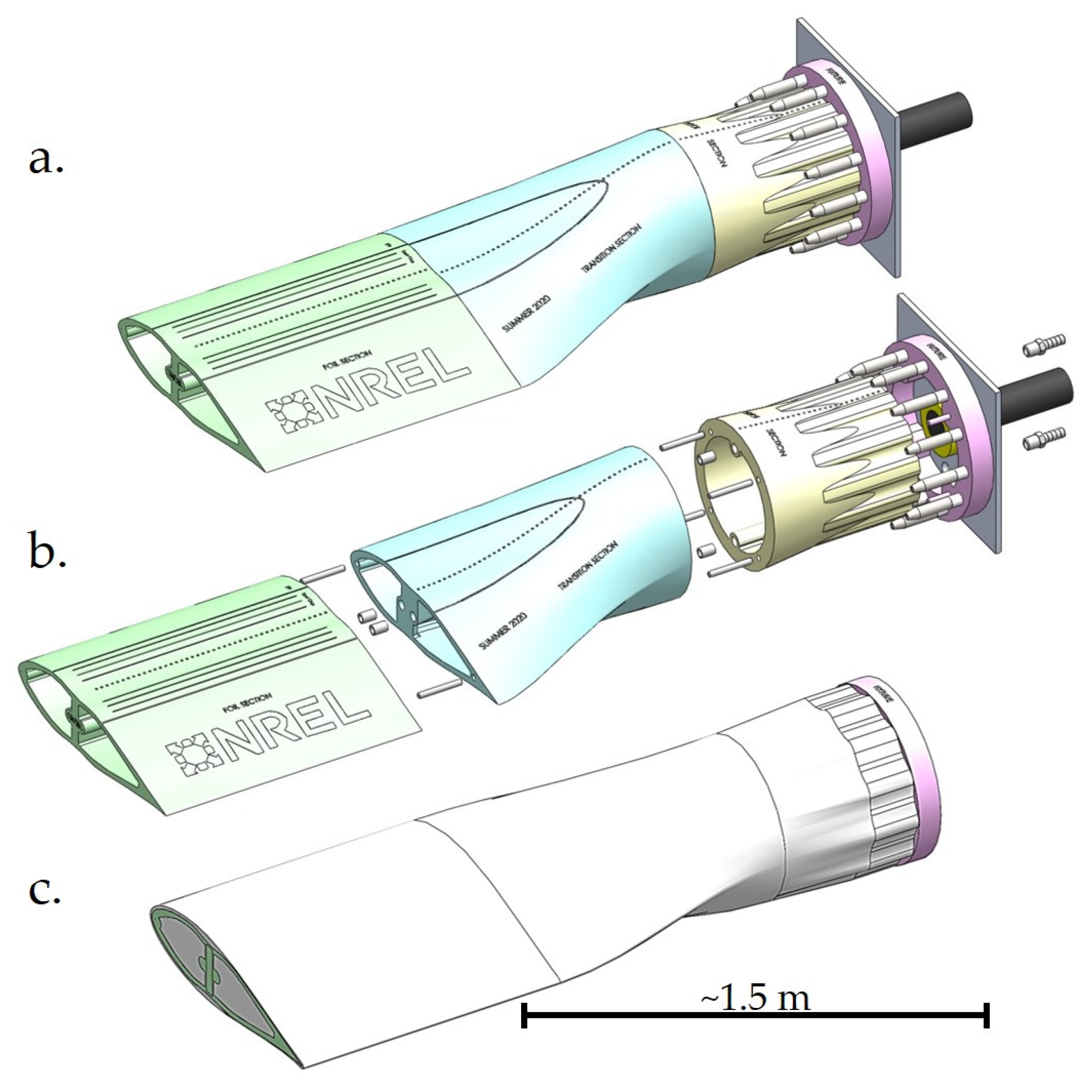
2.1. Key Features
2.2. Conceptual Design
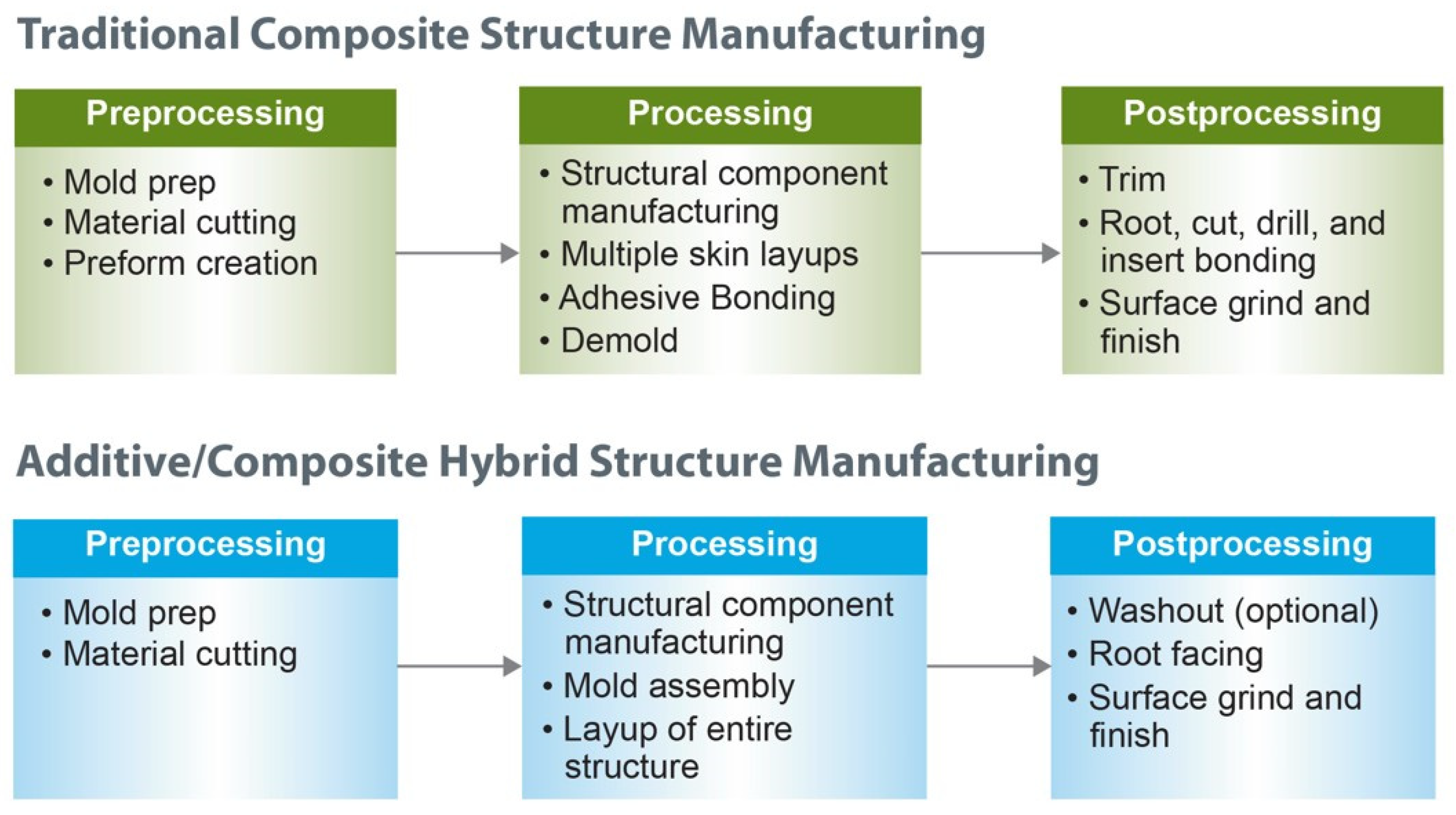
3. Manufacturing
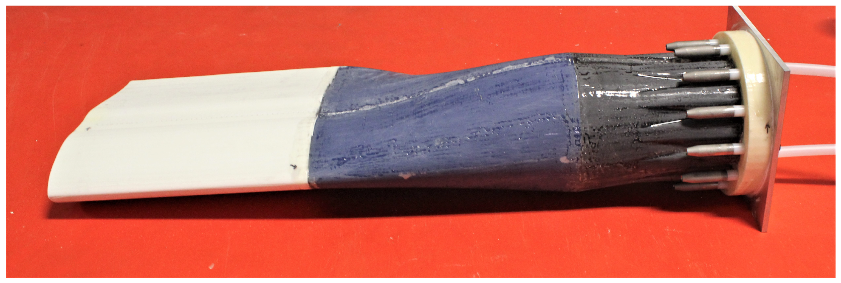
3.1. Additively Manufactured Mold Preparation
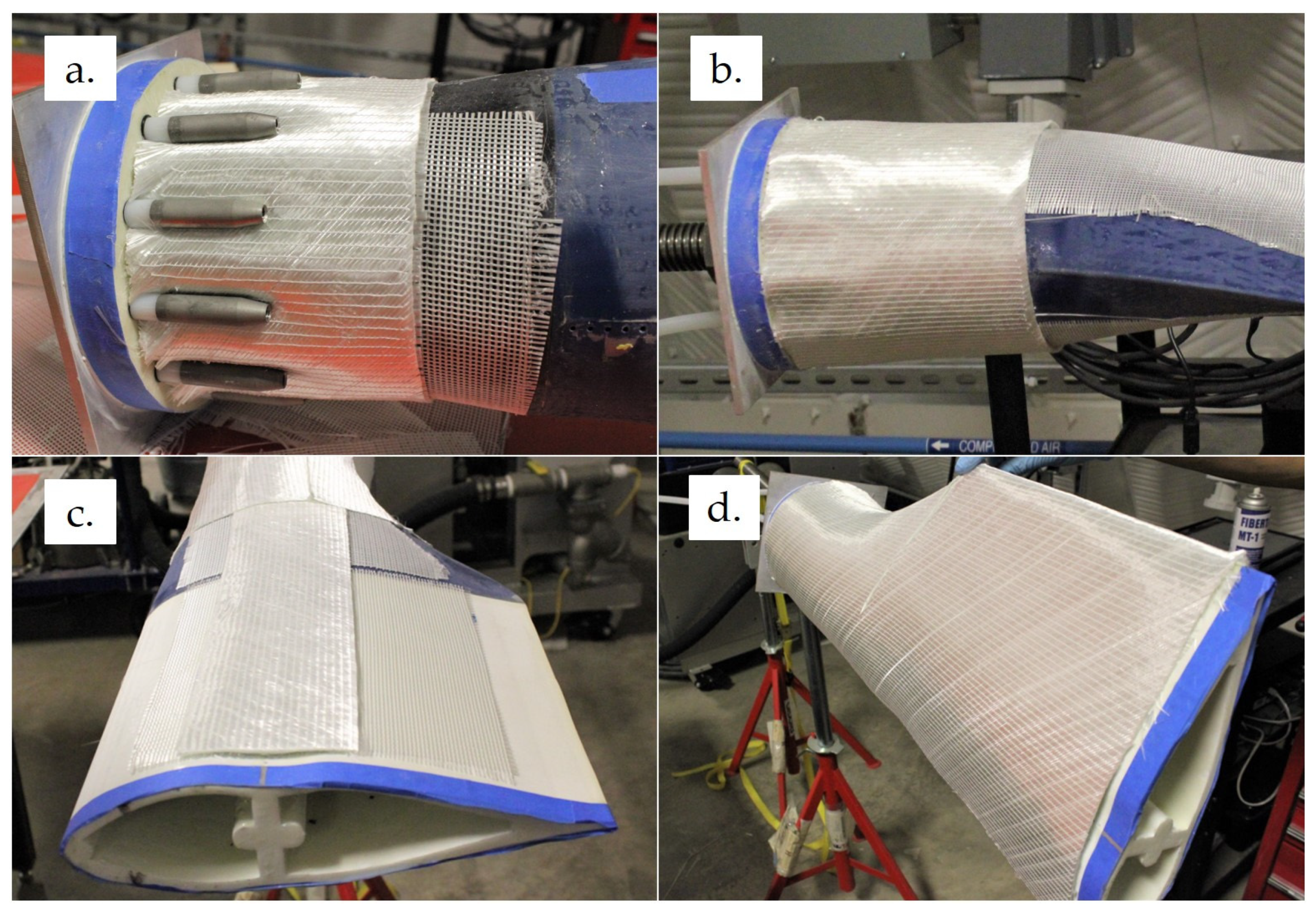
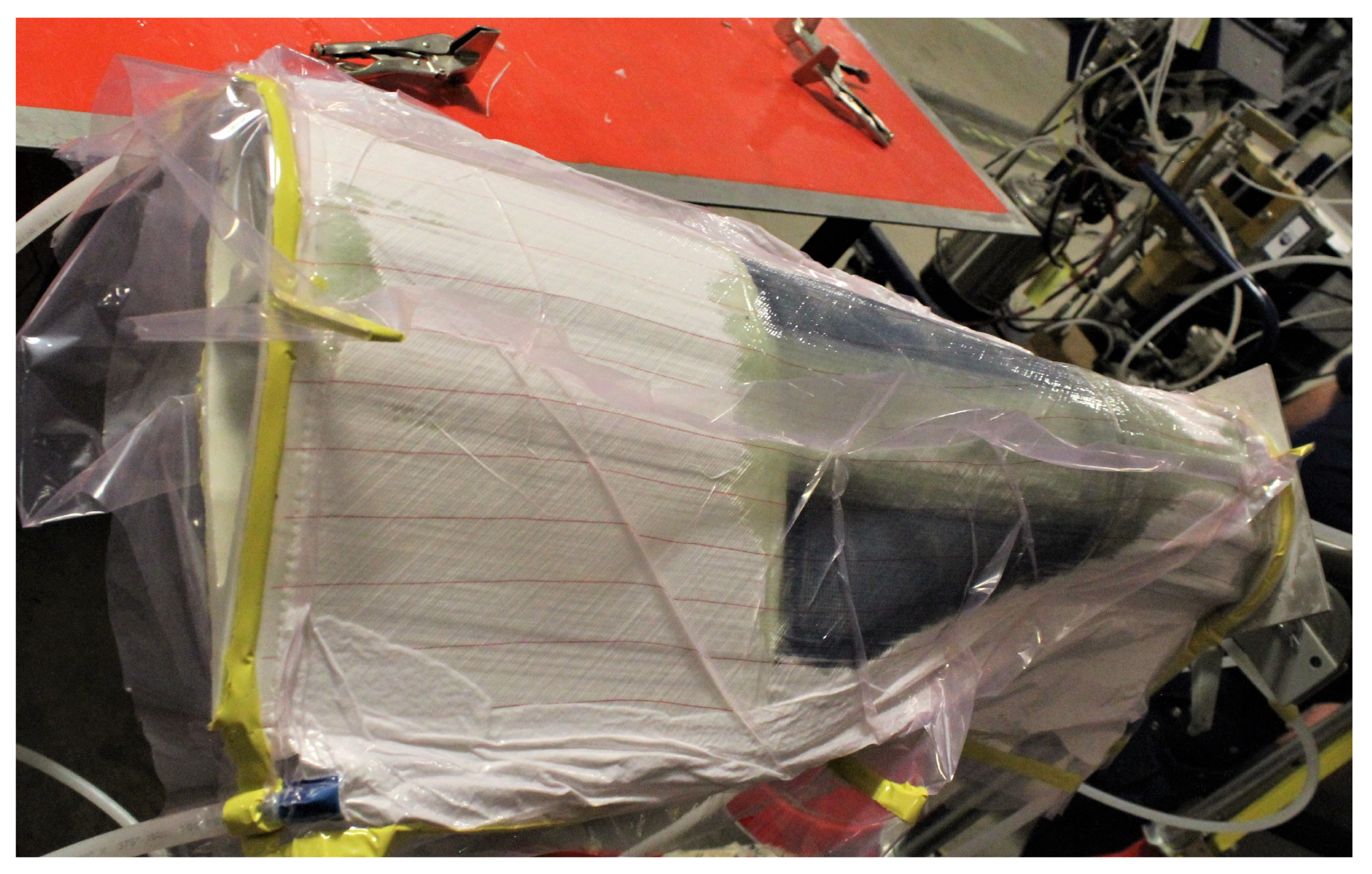
3.2. Composite Layup and Infusion
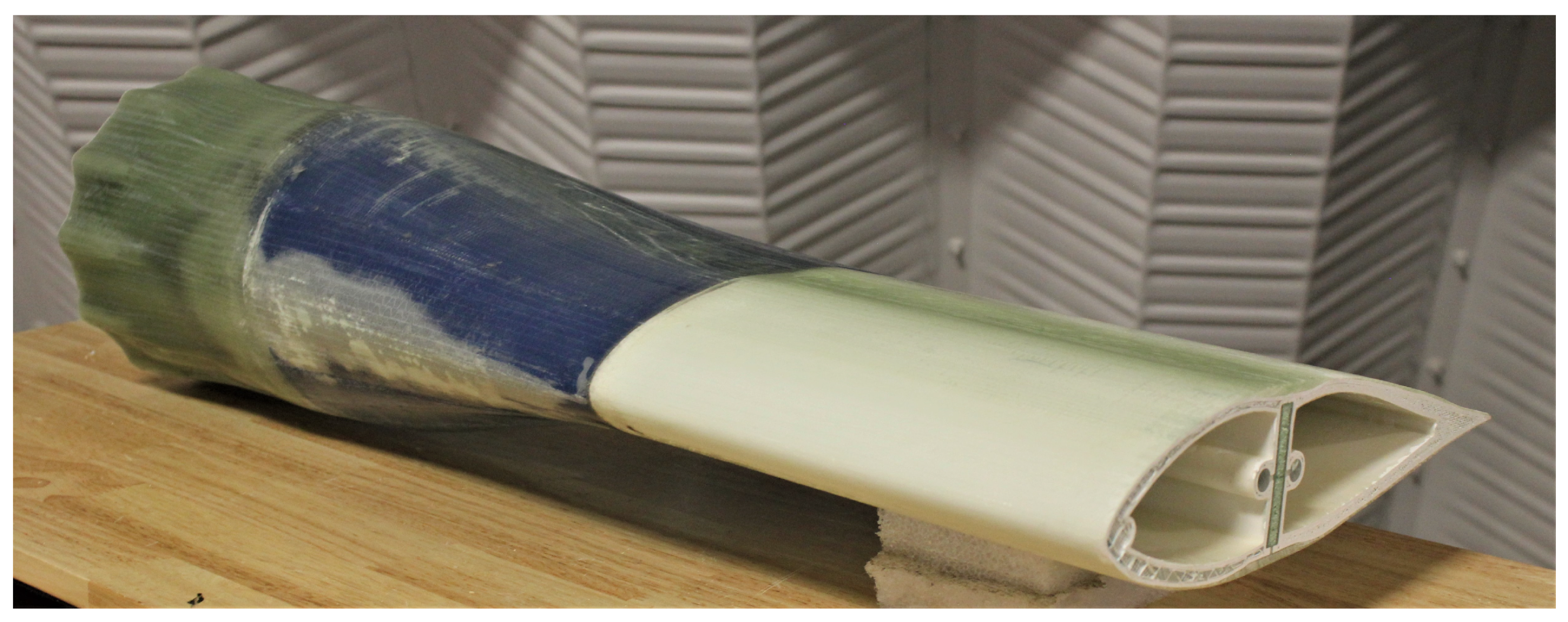
3.3. Final Finishing
4. Discussion
4.1. Mold Design
4.2. Manufacturing
Author Contributions
Funding
Institutional Review Board Statement
Informed Consent Statement
Data Availability Statement
Acknowledgments
Conflicts of Interest
References
- Neary, V.S.; Previsic, M.; Jepson, R.A.; Lawson, M.J.; Yu, Y.H.; Copping, A.E.; Fontaine, A.A.; Hallet, K.C.; Murray, D.K. Methodology for Design and Economic Analysis of Marine Energy Conversion (MEC) Technologies; Sandia National Larboratories: Albuquerque, NM, USA, 2014. [Google Scholar]
- Nunemaker, J.D.; Voth, M.M.; Miller, D.A.; Samborsky, D.D.; Murdy, P.; Cairns, D.S. Effects of moisture absorption on damage progression and strength of unidirectional and cross-ply fiberglass-epoxy laminates. Wind Energy Sci. 2018, 3, 427–438. [Google Scholar] [CrossRef] [Green Version]
- Bir, G.; Lawson, M.J.; Li, Y. Structural design of a horizontal-axis tidal current turbine composite blade. In Proceedings of the ASME 30th International Conference on Ocean, Offshore and Arctic Engineering, Rotterdam, The Netherlands, 19–24 June 2011. [Google Scholar] [CrossRef] [Green Version]
- Murray, R.E.; Jenne, S.; Snowberg, D.; Berry, D.; Cousins, D.S. Techno-economic analysis of a megawatt-scale thermoplastic resin wind turbine blade. Renew. Energy 2019, 131, 111–119. [Google Scholar] [CrossRef]
- Post, B.; Richardson, B.; Lloyd, P.; Love, L.; Nolet, S.; Hannan, J. Additive Manufacturing of Wind Turbine Molds; Oak Ridge National Laboratory: Oak Ridge, TN, USA, 2017. [Google Scholar] [CrossRef] [Green Version]
- Post, B.K.; Chesser, P.C.; Roschli, A.C.; Love, L.J.; Gaul, K.T. Large-Scale Additive Manufacturing for Low Cost Small-Scale Wind Turbine Manufacturing; Oak Ridge National Laboratory: Oak Ridge, TN, USA, 2018. [Google Scholar] [CrossRef]
- Post, B.K.; Richardson, B.; Lind, R.; Love, L.J.; Lloyd, P.; Kunc, V.; Rhyne, B.J.; Roschli, A.; Hannan, J.; Nolet, S.; et al. Big Area Additive Manufacturing Application in Wind Turbine Molds. In Proceedings of the 28th Annual International Solid Freeform Fabrication Symposium—An Additive Manufacturing Conference, Austin, TX, USA, 7–9 August 2017. [Google Scholar]
- Bassett, K.; Carriveau, R.; Ting, D.S.K. 3D printed wind turbines part 1: Design considerations and rapid manufacture potential. Sustain. Energy Technol. Assess. 2015, 11, 186–193. [Google Scholar] [CrossRef]
- Li, H.; Taylor, G.; Bheemreddy, V.; Iyibilgin, O.; Leu, M.; Chandrashekhara, K. Modeling and characterization of fused deposition modeling tooling for vacuum assisted resin transfer molding process. Addit. Manuf. 2015, 7, 64–72. [Google Scholar] [CrossRef]
- Wang, X.; Jiang, M.; Zhou, Z.; Gou, J.; Hui, D. 3D printing of polymer matrix composites: A review and prospective. Compos. Part B Eng. 2017, 110, 442–458. [Google Scholar] [CrossRef]
- van der Kilft, F.; Koga, Y.; Todoroki, A.; Ueda, M.; Hirano, Y.; Matsuzaki, R. 3D Printing of Continuous Carbon Fibre Reinforced Thermo-Plastic (CFRTP) Tensile Test Specimens. Open J. Compos. Mater. 2016, 6, 18–27. [Google Scholar] [CrossRef] [Green Version]
- Stratasys. FDM for Composite Tooling 2.0: Design Guide; Stratasys, Ltd.: Eden Prairie, MN, USA, 2017. [Google Scholar]
- Murray, R.E.; Snowberg, D.; Berry, D.; Beach, R.; Rooney, S.; Swan, D. Manufacturing a 9-meter thermoplastic composite wind turbine blade. In Proceedings of the American Society for Composites 32nd Technical Conference, West Lafayette, IN, USA, 23–25 October 2017. [Google Scholar] [CrossRef] [Green Version]
- Murray, R.E.; Beach, R.; Barnes, D.; Snowberg, D.; Berry, D.; Rooney, S.; Jenks, M.; Gage, B.; Boro, T.; Wallen, S.; et al. Structural validation of a thermoplastic composite wind turbine blade with comparison to a thermoset composite blade. Renew. Energy 2021, 164, 1100–1107. [Google Scholar] [CrossRef]
- Camanho, P.P.; Matthews, F.L. Stress analysis and strength prediction of mechanically fastened joints in FRP: A review. Compos. Part A Appl. Sci. Manuf. 1997, 28, 529–547. [Google Scholar] [CrossRef] [Green Version]
- Al-Khudairi, O.; Hadavinia, H.; Little, C.; Gillmore, G.; Greaves, P.; Dyer, K. Full-Scale Fatigue Testing of a Wind Turbine Blade in Flapwise Direction and Examining the Effect of Crack Propagation on the Blade Performance. Materials 2017, 10, 1152. [Google Scholar] [CrossRef] [PubMed] [Green Version]
- Chen, X.; Berring, P.; Madsen, S.H.; Branner, K.; Semenov, S. Understanding progressive failure mechanisms of a wind turbine blade trailing edge section through subcomponent tests and nonlinear FE analysis. Compos. Struct. 2019, 214, 422–438. [Google Scholar] [CrossRef] [Green Version]
- Jensen, F.M.; Falzon, B.G.; Ankersen, J.; Stang, H. Structural testing and numerical simulation of a 34 m composite wind turbine blade. Compos. Struct. 2006, 76, 52–61. [Google Scholar] [CrossRef]
- Lahuerta, F.; Koorn, N.; Smissaert, D. Wind turbine blade trailing edge failure assessment with sub-component test on static and fatigue load conditions. Compos. Struct. 2018, 204, 755–766. [Google Scholar] [CrossRef]
- Murray, R.E.; Roadman, J.; Beach, R. Fusion joining of thermoplastic composite wind turbine blades: Lap-shear bond characterization. Renew. Energy 2019, 140, 501–512. [Google Scholar] [CrossRef]
- Türk, D.-A.; Kussmaul, R.; Zogg, M.; Klahn, C.; Leutenecker-Twelsiek, B.; Meboldt, M. Composites Part Production with Additive Manufacturing Technologies. Procedia CIRP 2017, 66, 306–311. [Google Scholar] [CrossRef]
- Türk, D.-A.; Triebe, L.; Meboldt, M. Combining Additive Manufacturing with Advanced Composites for Highly Integrated Robotic Structures. Procedia CIRP 2016, 50, 402–407. [Google Scholar] [CrossRef] [Green Version]
- Murdy, P. Combining Acoustic Emission and Guided Ultrasonic Waves for Global Property Prediction and Structural Health Monitoring of Glass Fiber Composites. Ph.D. Thesis, Montana State University, Bozeman, MT, USA, 2018. [Google Scholar]
- Cousins, D.S.; Suzuki, Y.; Murray, R.E.; Samaniuk, J.R. Recycling glass fiber thermoplastic composites from wind turbine blades. J. Clean. Prod. 2019, 209, 1252–1263. [Google Scholar] [CrossRef]
- Rybnicek, J.; Lach, R.; Lapcikova, M.; Steidl, J.; Krulis, Z.; Grellmann, W.; Slouf, M. Increasing recyclability of PC, ABS and PMMA: Morphology and fracture behavior of binary and ternary blends. J. Appl. Polym. Sci. 2008, 109, 3210–3223. [Google Scholar] [CrossRef]
- Singh, R.; Singh, S.; Singh, I.P.; Fabbrocino, F.; Fraternali, F. Investigation for surface finish improvement of FDM parts by vapor smoothing process. Compos. Part B Eng. 2017, 111, 228–234. [Google Scholar] [CrossRef]
- Murdy, P.; Hughes, S. Investigating Core Gaps and the Development of Subcomponent Validation Methods for Wind Turbine Blades: Preprint. In Proceedings of the AIAA SciTech Forum, Orlando, FL, USA, 6–10 January 2020. [Google Scholar] [CrossRef]


Publisher’s Note: MDPI stays neutral with regard to jurisdictional claims in published maps and institutional affiliations. |
© 2021 by the authors. Licensee MDPI, Basel, Switzerland. This article is an open access article distributed under the terms and conditions of the Creative Commons Attribution (CC BY) license (http://creativecommons.org/licenses/by/4.0/).
Share and Cite
Murdy, P.; Dolson, J.; Miller, D.; Hughes, S.; Beach, R. Leveraging the Advantages of Additive Manufacturing to Produce Advanced Hybrid Composite Structures for Marine Energy Systems. Appl. Sci. 2021, 11, 1336. https://doi.org/10.3390/app11031336
Murdy P, Dolson J, Miller D, Hughes S, Beach R. Leveraging the Advantages of Additive Manufacturing to Produce Advanced Hybrid Composite Structures for Marine Energy Systems. Applied Sciences. 2021; 11(3):1336. https://doi.org/10.3390/app11031336
Chicago/Turabian StyleMurdy, Paul, Jack Dolson, David Miller, Scott Hughes, and Ryan Beach. 2021. "Leveraging the Advantages of Additive Manufacturing to Produce Advanced Hybrid Composite Structures for Marine Energy Systems" Applied Sciences 11, no. 3: 1336. https://doi.org/10.3390/app11031336