Abstract
The use of organic Rankine cycles (ORCs) is a viable solution for the recovery of waste heat. For an air separation unit (ASU) with a production of operating in Romania, the value of utilization of the heat transferred to the cooling system of the compression area represents 21% of the global system electrical energy input. To recover this thermal energy and transform it into mechanical energy, an ORC system was proposed. To maximize the production of mechanical power, an exergy analysis was performed. Exergy analysis was used to choose the most suitable organic fluid and find the optimum constructive structure of the Rankine cycle. The calculation of the exergy destruction in the key apparatuses of the system allowed investigation into the optimization search procedure. The large exergy destruction in the liquid preheater suggested the decrease in the temperature difference in this part of the evaporator by increasing the inlet temperature of the liquid; and an internal recuperative heat exchanger was used for this purpose. When permitted, the overheating of the vapors also reduced the temperature difference between the heat source and the organic fluid during the heat transfer process. The analysis was comparatively performed for several organic fluids such as R-245fa, R123, n-pentane and R717. The use of ammonia, that offered the possibility of superheating the vapors at the turbine inlet, brought a gain of mechanical power corresponding to 6% economy in the electrical energy input of the global plant.
1. Introduction
When there is a heat source at a higher temperature than the environment, there is a possibility of transforming it into mechanical energy with the help of a power cycle. This also occurs if the cold source of the power cycle is at a lower temperature than the environment, in which case, some of the mechanical energy consumed to obtain the low temperature cold source can be recovered [1].
Power cycles can be open, in which the air represents the working fluid that is introduced in the cycle at the parameters of the environment, or closed, in which the working fluid has a different composition to that of the environment [1]. In the case of closed Rankine cycles, the advantage of achieving heat exchanges with hot and cold sources at almost constant temperatures, leads to an increase in the energy efficiency of the cycle, bringing it closer to that of the Carnot cycle. To this, the advantage of increasing the fluid pressure in the liquid phase is added; the increase in pressure is achieved by a practically insignificant consumption of mechanical energy in the pump [1].
The use of organic fluids in Rankine cycles leads to simple functional schemes in which, for fluids with complex molecular composition, the appearance of liquid is avoided during the expansion process in the expander. The use of high molecular weight organic fluids has the effect of reducing the enthalpy drop in the expander which leads to a decrease in its number of stages or to a decrease in the peripheral speed at the exit of the turbine [2,3,4]. The choice of organic fluids with higher critical temperatures but appropriate to those of the heat sources leads to condensation pressures higher than the ambient pressure, thus eliminating the special measures for sealing the condenser [5,6,7,8,9].
In the analysis of the recovery of limited heat sources at moderate heat levels, the research focused on optimizing the operation and construction of ORC schemes looking for investigative methods to highlight and quantify the negative effects of malfunctions associated with internal processes.
The technique of investigation chosen by most researchers is the exergetic method based on the union between the First and Second Laws of Thermodynamics [10,11,12]. An energy and exergy analysis of the integration of an ORC in a solid oxide fuel cell (SOFC) system was performed by Ahmadi M.H. et al. [13]. The ORC used, as heat sink, a stream of LNG on its way to regasification, and as heat source it used the flue gas generated by the afterburner of the SOFC that later is expanded in a gas turbine. The work calculated the exergetic performances of the key parts of the system, offering information about opportunities of improvement. Effatpanah S.K. et al. [14] conducted an exergoeconomic analysis of the recovery of heat waste from a biomass combustion process with the use of ORC. The analysis revealed that the most destructive parts of the ORC were the evaporator and the turbine. The exergoeconomic analysis enabled the determination of the monetary cost of the output power and the capital investment amortization rate of the key apparatuses. Shamoushaki M. et al. [15] conducted a comprehensive analysis and optimization of different configurations of power cycles. The method of analysis combined the energetic and exergoeconomic balances. The study pointed out the advantages of using a simple ORC in terms of the power generation cost and pay-back period. Feng Y. et al. [16] used the concept of entropy generation and entransy dissipation [17,18,19] to analyze a basic ORC operating with mixtures of working fluids. They studied the effect of the temperature glides in the evaporator and condenser on the irreversibility of heat transfer under a finite temperature difference. They found a minimum entropy generation in the evaporator for a mixture of R245fa and pentane, while in other pieces of equipment, other pairs of organic fluids reported minimum entropy generation.
Liu C. et al. [20] studied, based on the Second Law of Thermodynamics, the influence of the evaporation temperature on the performance of subcritical ORC. The analysis considered 28 working fluids used in an ORC to recover waste heat. They studied the influence of the critical temperatures of the working fluids on the choice of the optimum temperature of evaporation. The work reported recommendations for the temperature difference between the critical temperature of the organic fluid and the temperature of the waste heat source for an optimum evaporation temperature that led to a maximum Second Law efficiency.
In [21], Ho Yong Lee and Kyoung Hoon Kim discussed the use of LNG as a heat sink in a combined power cycle composed of an ORC and an LNG power generation by direct expansion. The analysis considered different organic fluids and accounted for the influence of the critical temperature of the working fluids and inlet pressure in the turbine on the mechanical power and cycle efficiency.
An analysis of a combined heat and power engine fueled with biogas and subcritical or supercritical organic Rankine cycles was performed by Koc Y. et al. [22]. The study, based on exergy analysis, sought to determine the best operational conditions to achieve the maximum mechanical work from the recovered heat carried by the flue gas of the thermal engine. They reported the highest exergy destruction in the evaporator. The paper reached the conclusion that the best performance was achieved by the subcritical ORC with a regenerative heat exchanger.
Exergetic analysis was used by Liu G. et al. [23] to determine the best functional parameters for the efficient operation of the power system using two organic Rankine cycles running separately at two different heating temperatures. Several organic fluids were comparatively studied. The mass flow rate of the hot carrying fluid was split into two branches that fed the evaporators of the two ORC stages. The splitting ratio of the mass flow rate was a decisional parameter in the optimization search procedure. The work determined the organic fluids and their splitting ratio for supplying both evaporators of the two-stage system, suitable for different heat source temperatures.
The optimization of an organic Rankine cycle and the nature of the fluids’ influence on the performance of the system were studied by Fergani Z. et al. [24]. The analysis was based on the exergy concept, and the optimum search appealed for multi-objective optimization. The exergoeconomic model offered economical correlations for estimating the investment cost of the key pieces of equipment. The exergetic efficiency and the unitary monetary cost of the product of the system were calculated at the variation of the composition of the zeotropic mixture. The exergoeconomic analysis determined the most cost destructive processes, and the most expensive apparatuses. The conclusion was that, compared with operating with their pure components, the use of zeotropic mixtures in ORC brought an increase in the performance of the cycle. Dorosz P. et al. [25] coupled an LNG system with power delivery by direct expansion with the condenser of an ORC, and recovered a part of the necessary heat for regasification. The performances of the cycle were ranked based on exergetic efficiency, and the decisional parameters were the pumping pressures in the LNG and ORC systems.
The present paper, based on exergetic analysis, aims to reveal the malfunctions associated with the working processes, offering a strategy for functional and structural optimization. The magnitude and location of exergy destructions will guide the search for the most efficient operating regime and system configuration.
2. Potential for Recovery of Heat from the Cryogenic Air Separation Unit
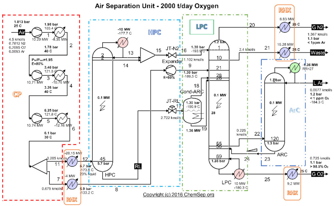
An analysis of the evacuated heat recovery potential was performed for the cryogenic air separation unit (ASU) (Figure 1) operating on the platform of the Galati Iron and Steel Works, Romania [26].

Figure 1.
Schematic of the cryogenic air separation installation–functional areas. Source: Harry Kooijman (2006) chemsep.org [26].
Highlighting as final products of the installation the currents of oxygen gas, nitrogen gas and liquid argon (Figure 1 and Table 1), and as resource (fuel) the electricity consumed to drive the compressors (Figure 1 and Table 2), the exergetic analysis of the installation showed a global exergetic performance coefficient of 14% (Equation (1)) [26].

Table 1.
Compressors input powers [26].
Table 2.
Values of the exergetic products [26].
The exergetic performance coefficient of the whole system is:
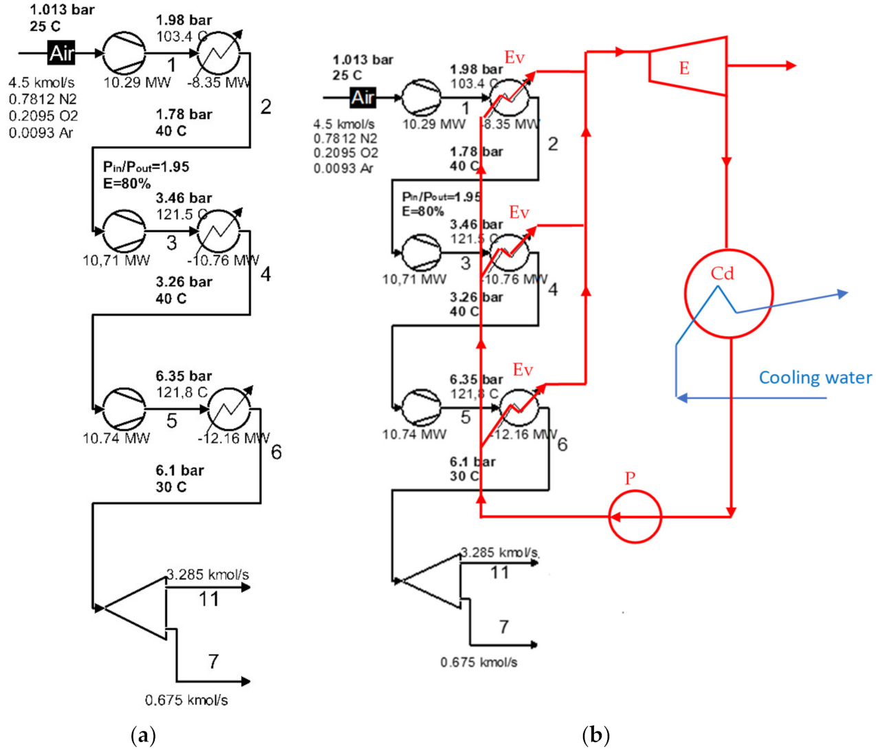
The exergetic analysis of the installation demonstrated that the compression stage (Figure 2a) represented an area with a major destruction of exergy (consumption of electricity).
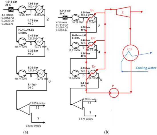
Figure 2.
Schematic of the compression area of the cryogenic air separation unit: (a) the initial compression area; (b) schematic of the use of ORC for intermediate and final cooling of compressors.
Table 3 shows the exergy destructions due to the irreversibility of the compression processes in the compression stages, and Table 4 shows the exergy losses with the heat transferred in the intermediate coolers and the final of the compression stages [26].
Table 3.
Exergy destruction in the compression stages [26].
Table 4.
Losses with heat exergies evacuated in the coolers of the compression stages [26].
The sum of exergy losses and destruction in the compression zone is:
The share of exergy losses and destruction in the compression zone in the fuel consumption of the global installation is:
It was observed that 37% of the electricity consumption of the global installation was dissipated in the irreversible processes of the compression zone (Equations (2) and (3)) [26].
Of this exergy consumption, more than half (21% of global consumption) represented the exergy loss with the heat transferred to the environment (Equation (4)) [26].
If the reduction in the exergy destruction associated with the compression process is largely impossible to counteract due to the limited isentropic efficiency of the compressors, conversely, the heat dissipated in the cooling system of the compressors is a source of recoverable energy with a major consequence for increasing the efficiency of the global system.
In the case of an installation of the complexity and quantity of product of the size of the cryogenic air separation unit of the Galati Iron and Steel Works, the heat recovery and its transformation into electricity will be a solution of interest.
Due to the relatively low average temperature level (70–80 °C) of the heat discharged by the compressor cooling system, a viable solution would be to transform this heat into mechanical work (electricity) using a Rankine cycle running on organic fluids.
Instead of using cooling water in the intermediate coolers and the final cooler, an organic fluid is proposed to be used, which is also the working fluid of the Rankine cycle.
3. The Recovery of the Heat Discharged from the Compressors Cooling System Using a Rankine Cycle with Organic Fluids
A flow chart of the heat recovery from the compressors cooling system of the cryogenic air separation unit using a Rankine cycle with organic fluids (ORC) is shown in Figure 2b.
According to Figure 2b, the organic fluid was divided into three streams that receive, in parallel, the heat from the air coolers of the compression stage. The distribution of the mass flow of the organic fluid was conducted in proportion to the thermal load of each chiller, to ensure that each of the streams of organic fluid were heated to the same temperature. After the heat recovery, the gaseous organic fluid expanded into the expander of the ORC system, eventually producing electricity.
The inlet and outlet temperatures of the hot fluid (compressed air) in the evaporator are shown in Table 5 and Figure 2.
Table 5.
The potential for recovery of the heat discharged by the compression stage of the ASU.
The potential for recovery of the heat discharged by the compression stage of the ASU is shown in Table 5.
3.1. Rankine Cycles with Organic Fluids
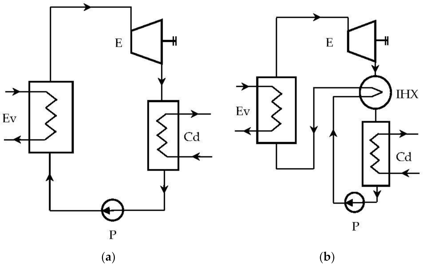
In the case of ORC cycles operating “dry”, a recuperative (internal) heat exchanger can be provided, which, based on the high thermal potential of the expander outlet, can preheat the liquid (Figure 3b).

Figure 3.
Rankine system with organic fluids: (a) ORC system without internal heat exchanger (IHX); (b) ORC system with IHX.
3.2. Organic Fluids
An important feature of organic fluids is the slope of the dry saturated vapor curve in the T-s diagram, a slope that imposes the state of the fluid at the exit of the expander after adiabatic expansion.
Depending on the slope of the vapor saturation curve, organic fluids fall into three categories:
- (a)
- “Wet” fluids that have a negative vapor saturation curve slope-example: NH3, R152a, R134a;
- (b)
- “Dry” fluids that have a positive vapor saturation slope-example: n-pentane, R236fa, R141b;
- (c)
- “Isentropic” fluids with an infinite slope, the vapor saturation curve being practically perpendicular to the entropy axis-example: R-245fa, R-123.
Cycles running on dry or isentropic fluids were expected to have higher efficiencies than those using wet fluids due to the absence, in the case of the former, of the condensation process it accompanied; and in the case of wet fluids, expansion in the expander.
4. Thermodynamic Analysis of ORC Cycles
The thermodynamic analysis aimed to model the operation of ORC cycles with different working agents and to simulate their behavior in conditions of coupling with the coolers of the compression area of the cryogenic air separation unit.
The selected organic fluids belong to all the categories discussed [27,28,29,30]:
- (1)
- Wet fluids: NH3;
- (2)
- Isentropic fluids: R123, R245fa (single component fluids with excellent environmental properties that replace Freon-11 which is being phased-out);
- (3)
- Dry fluids: n-pentane.
4.1. ORC Cycle with Non-Negative Vapor Saturation Curve Slope without Vapor Overheating at the Inlet to the Expander and without Internal Recuperator Heat Exchanger
The schematic of the ORC system and the representation of the cycle in the diagram T-s, are shown in Figure 4.
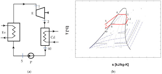
Figure 4.
ORC system without overheating of the vapors at the entrance to the expander and without internal recuperative heat exchanger: (a) flow chart; (b) representation in the T-s diagram of the ORC cycle.
Figure 4b shows that the cycle, in the chosen functional variant, worked with the subcooling of the condensed liquid.
4.2. ORC Cycle with Non-Negative Vapor Saturation Curve Slope, without Overheating of Vapors at the Inlet to the Expander, with Internal Heat Exchanger
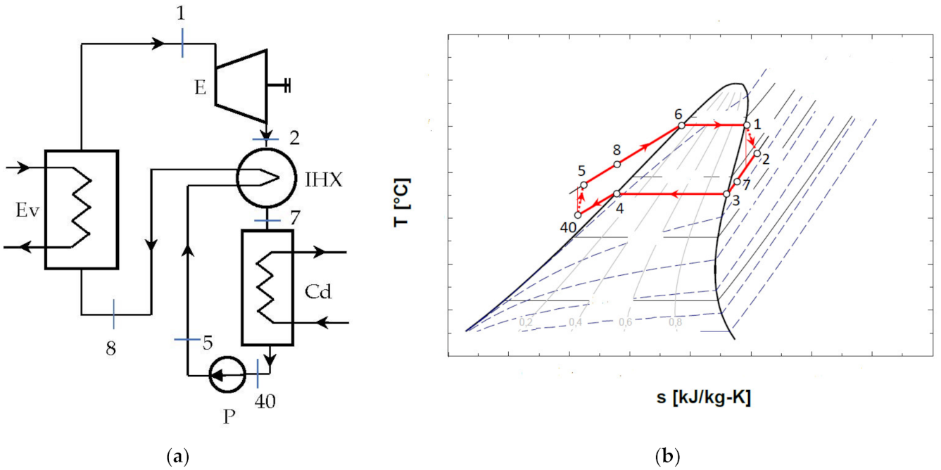
The diagram of the ORC system with internal heat exchanger recuperator, and the representation of the cycle in the diagram T-s, are presented in Figure 5.
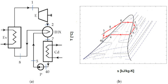
Figure 5.
ORC system without overheating and with internal heat exchanger recuperator: (a) schematic of the system; (b) representation in the T-s diagram of the ORC cycle.
4.3. ORC Cycle with Non-Negative Vapor Saturation Curve Slope with Vapor Overheating at the Inlet to the Expander and with Internal Heat Exchanger
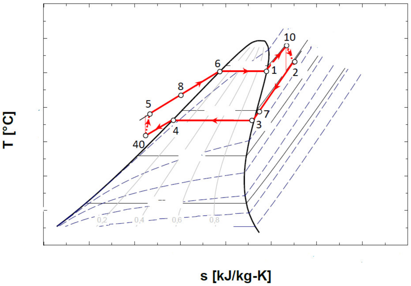
The representation in the T-s diagram of the ORC cycle with the overheating of the vapors before entering the expander and with the internal recuperative heat exchanger, is shown in Figure 6.
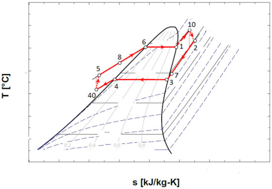
Figure 6.
Representation in the T-s diagram of the ORC cycle with the overheating of the vapors at the entrance to the expander and with the internal heat exchanger recuperator.
4.4. Mathematical Modeling and Energy Analysis of the ORC Cycle
The design of the mathematical model was conducted for the scheme without an internal heat exchanger and without overheating of the vapors at the exit of the evaporator (Figure 4); for the other schemes, the main elements such as the choice of vaporization and condensation temperatures remained unchanged.
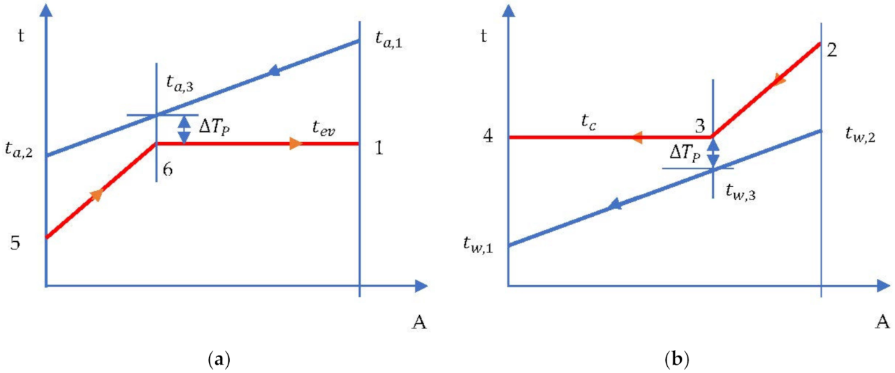
- The evaporation temperature was imposed by the minimum temperature difference in the evaporator (temperature difference at Pinch) which occurred at the end of heating the liquid in the evaporator and the beginning of evaporation (Figure 7a).
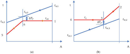 Figure 7. ORC cycle without overheating and without internal heat exchanger. Temperature-area of heat transfer (t-A) diagram: (a) evaporator; (b) condenser.
Given:
- ☑
- Air temperatures and at the inlet and outlet of the cooler, respectively;
And designer’s choices:
- ☑
- The nature of the ORC fluid;
- ☑
- The minimum temperature difference ;
Then:
- ☑
- The vaporization temperature of the ORC fluid is determined.
- ☑
- From the energy balance of the vaporization zone the temperature, tev, results.
The system consisting of Equations (5)–(8) has four variables, namely, , and is, therefore, determined. The enthalpy in state 5 is determined in a subsequent procedure when running the cycle.
- Condensation temperature is determined by the temperature of the cooling water and the minimum temperature difference in the condenser (temperature difference at Pinch ) (Figure 7b).
Given:
- ☑
- Water temperature at the condenser inlet;
And designer’s choices:
- ☑
- The increase in condenser cooling water temperature ;
- ☑
- The minimum temperature difference ∆Tp in the condenser;
Then:
- ☑
- The condensation temperature of the ORC fluid is determined.
The energy balance of the condenser is:
The four Equations (9)–(12) have four variables:.
The expander output:
The pump input:
The net output of the ORC:
The energetic COP of the ORC:
4.5. Exergetic Analysis of the ORC Cycle
To define an operational and constructive optimization strategy, the exergetic method was used, which identified the place and size of a malfunction in the system [31,32].
The exergetic balance equation for the cycle without overheating and without internal recuperator heat exchanger (Figure 4) is:
For the ORC cycle, and the rest of the terms of Equation (17) become:
Substituting relationships (18) and (19) in the relation (17) we obtain:
Noting that the heat flow to the evaporator was obtained from the cooled compressed air stream, and considering the destruction of exergy due to the heat transfer at the finite temperature difference in the evaporator, the balance Equation (20) becomes:
in which:
where represents the exergy of the available heat carried by the air that is the fuel of the system.
The exergetic efficiency is:
The share of an exergy destruction in the exergy of the heat available for recovery becomes:
5. Study of the Performance of the ORC Cycle Working with Different Organic Substances
The ORC system recovered the heat evacuated by the coolers of the compression area of the cryogenic air separation unit to transform it into mechanical (electrical) energy.
To correctly estimate the real performance of the system, an exergetic analysis was performed, which highlighted the functional areas with potential for improvement, which allowed the establishment of a strategy for the functional and constructive optimization of the ORC system. A simulation of the operation of the organic Rankine cycles was performed with the EES program [33].
In all studied cases, the isentropic efficiencies of the expanders and pumps were and , respectively. The condensing temperature was , under the conditions in which the cooling water of the condenser before entering the condenser was cooled by means of the residual nitrogen discharged from the low-pressure distillation column. To ensure all the heat exergies were positive, the reference ambient temperature was chosen as .
To counteract the decrease in the temperature at the pinch point in the evaporator with the increase in the vaporization temperature, the condensed liquid was subcooled before the suction in the pump (Figure 4, Figure 5 and Figure 6).
5.1. Study of the Performance of the ORC Cycle Operating with R-245fa
The decisional parameter according to which the optimization study was conducted, was the evaporation temperature, .
In the case of R-245fa, the evaporation temperature varied in the range of .
5.1.1. ORC System with R-245fa without Overheating and without Internal Recovery Heat Exchanger
The schematic of the system is presented in Figure 4. The results of the mathematical modeling based on the exergetic analysis of the ORC operating with R-245fa, without overheating and without internal heat exchanger, are presented in Table 6.
Table 6.
Energetic and exergetic measures for the ORC cycle with R-245fa, without overheating and without internal heat exchanger.
The exergetic balance is represented by the exergetic efficiency and the weights of the exergy destruction related to the exergy of the available heat to be recovered .
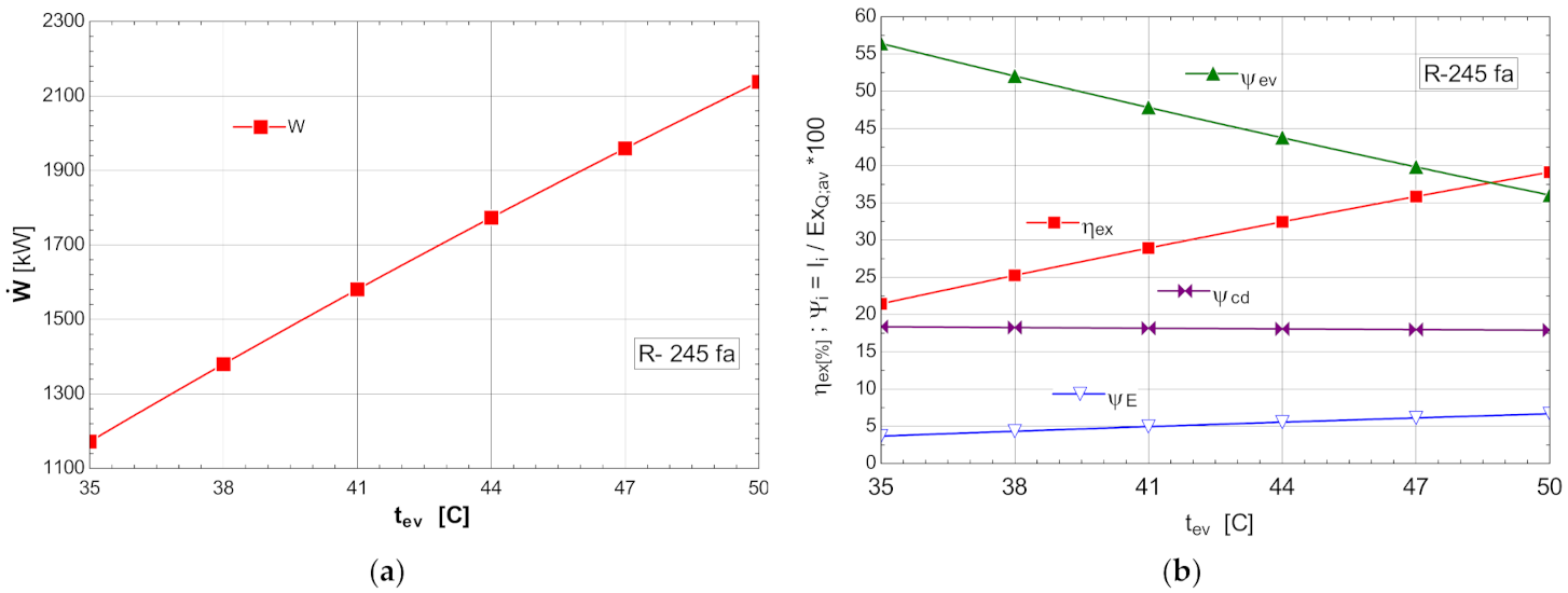
The variations of the energetic and exergetic measures at the change of the evaporation temperature are presented in Figure 8b.
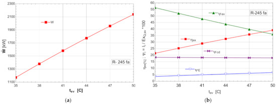
Figure 8.
ORC without overheating and without internal heat exchanger: (a) mechanical power, depending on the variation of the evaporation temperature ; (b) exergetic efficiency and weights of the exergy destruction relative to the exergy of the available recovered heat, depending on the variation of the evaporation temperature, .
As the evaporation temperature increased, the exergetic efficiency of the cycle rapidly increased (Figure 8b).
The exergy destructions with the highest weights corresponded to the processes in the vaporizer () and condenser–subcooler () (Figure 8b). Increasing the temperature of the organic fluid () that absorbed the recovered heat, reduced the anergy of this transfer process.
The increase in the temperature of the ORC fluid that received the heat recovered from the cooling system of the ASU compression area could be achieved by recovering, in an internal heat exchanger, the heat of the vapors from the outlet of the expander when the temperature difference allowed (Table 6).
As a result of the reduction in the exergy destruction in the vaporizer with the increase in the vaporization temperature, the mechanical power () produced by the ORC rapidly increased (Figure 8a).
5.1.2. ORC System with R-245fa without Overheating with Internal Recovery Hear Exchanger
The schematic of the system is presented in Figure 5.
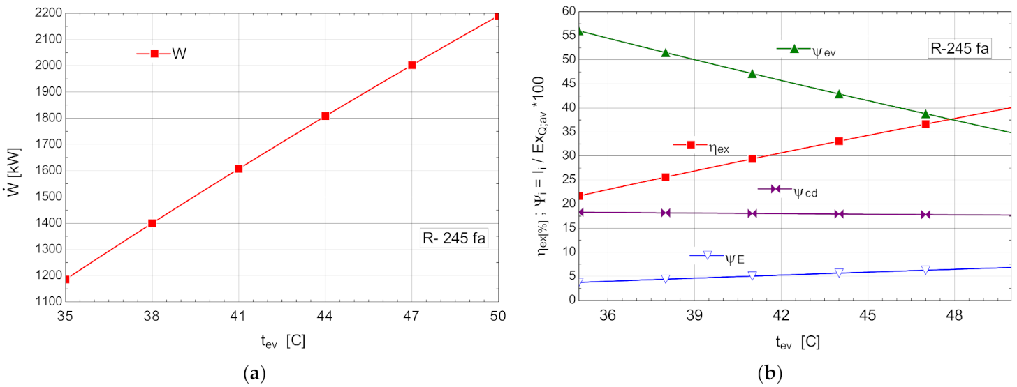
The high destruction of exergy in the vaporizer led to the introduction of an internal recuperative heat exchanger [34]. The primary goal was to increase the mechanical power under conditions of a steadily recovered heat flux. The influence of the variation of the evaporation temperature on the energetic and exergetic measures of the ORC with internal recuperative exchanger is presented in Figure 9.
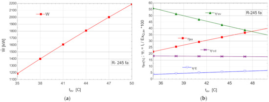
Figure 9.
ORC with internal heat exchanger and without overheating: (a) mechanical power, , depending on the variation of the evaporation temperature, ; (b) exergetic efficiency and weights of exergy destructions relative to the exergy of the recovered available heat, depending on the variation of the evaporation temperature, .
The efficiency of the internal recuperative heat exchanger was estimated at .
The results of the mathematical modeling based on the exergetic analysis of the ORC operating with R-245fa, without overheating, with internal heat exchanger are presented in Table 7.
Table 7.
Energetic and exergetic measures for the ORC with R-245fa, without overheating but with internal heat exchanger.
Compared with the scheme without the internal heat exchanger, the expected decrease in exergy destruction in the vaporizer was small, but considering the ORC mass flow rates, there was an increase in the mechanical power developed. Thermodynamically, the ORC with internal heat exchanger was more efficient than the one without the internal recuperator.
5.1.3. ORC System with R-245fa with Overheating and Internal Recovery Heat Exchanger
The schematic of the system is presented in Figure 6.
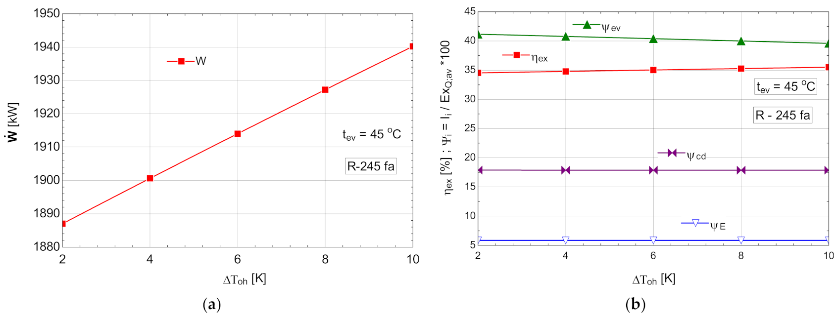
Starting from the most efficient variant characterized by the highest vaporization temperature that would allow the temperature difference prescribed at the pinch point to be ensured, an attempt to overheat the vapors above this temperature was conducted. For thermo-economic reasons imposed by the temperature difference at the pinch point, the temperature of evaporation was limited at 45 °C for all organic Rankine fluids. The results of the study with overheating for an evaporation temperature are presented in Table 8 and Figure 10.
Table 8.
Energetic and exergetic measures for the ORC with R-245fa, with overheating and with internal heat exchanger, .
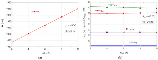
Figure 10.
ORC with internal heat exchanger and overheating: (a) mechanical power, , depending on the degree of overheating, ; (b) exergetic efficiency and weights of exergy destructions relative to the exergy of available recovered heat, depending on the variation of the degree of overheating, .
As expected, the increase in the degree of overheating led to a decrease in the exergy destruction of the evaporator-superheater in the conditions of maintaining a constant loss of exergy in the condenser (Figure 10b). The exergetic efficiency of the cycle increased (Figure 10b) in addition to the mechanical power output (Figure 10a).
Although the ORC flow rate decreased (Table 8), the developed mechanical power increased, which was a double positive effect.
To highlight the mechanism of reducing the destruction of exergy in the evaporator which led to the increase in the mechanical power developed by the system, the destruction of exergy was divided according to the areas of the evaporator-superheater. The apparatus that absorbed the heat from the cooling system of the ASU compression stage was divided into heating, evaporating and overheating areas.
The results of the comparative analysis for the three schemes—without overheating and without internal recovery exchanger (Figure 4), without overheating and with internal recovery exchanger (Figure 5), and finally, the scheme with overheating and internal recovery exchanger (Figure 6)—are presented in Table 9.
Table 9.
Comparative analysis: energetic and exergetic measures for different types of ORCs with R-245fa, ( ).
The comparative analysis presented in Table 9 shows the decreasing trend of exergy destruction in the evaporator as the temperature of the ORC fluid increased and the temperature difference between the air to be cooled and the ORC fluid, which receives the heat, decreases. This result is also confirmed by studies [35,36].
The addition of the internal recuperative heat exchanger (IHE) was intended to increase the temperature of the ORC fluid at the inlet to the vaporizer; the maneuver proved to be correct because the share of relative exergy destruction in the heating area of the evaporator (ψh) decreased (Table 9) from 4.8% to 3.743%, and decreased by almost a percentage, the overall relative destruction () in the vaporizer.
In the case of the ORC scheme with the fluid overheating (Figure 6), the decrease in the exergy destruction caused by the heat transfer at the finite temperature difference between the air and the ORC fluid was more pronounced—the evaporation (ψzev) and heating (ψh) zones were discharged by transferring part of the destruction to the overheating area (ψoh) (Table 9). Overall, the destruction of exergy associated with heat transfer in the evaporator-superheater decreased, reaching the lowest value compared with other schemes. Consequently, the value of the exergetic efficiency and the mechanical power produced were the highest for the scheme with overheating and internal recuperator changer.
5.2. Comparative Study of the Performance of the ORC Cycle Working with Different Organic Fluids
In the case of the organic fluid R245fa, the cycle with overheating and with internal recovery heat exchanger proved to be the most efficient. The performance of this scheme was also analyzed for other organic fluids with non-negative saturated vapor slopes, such as R123 and n-pentane.
From the category of “wet” fluids with a negative saturated vapor slope, NH3, a natural fluid, was chosen. In the case of NH3, the cycle was with expansion in the turbine up to the wet area, and consequently the internal recovery heat exchanger was missing.
5.2.1. The Performance Study of the R717 (NH3) ORC with Overheating Using R717 (NH3)
The energetic and exergetic measures for the ORC cycle with R-717, with overheating are presented in Table 10 and Figure 11.
Table 10.
Energetic and exergetic measures for the ORC cycle with R-717, with overheating, .
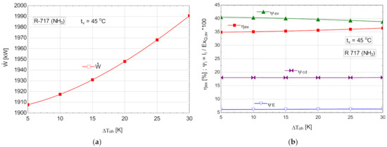
Figure 11.
ORC with R-717 with overheating: (a) mechanical power, depending on the degree of overheating, ; (b) exergetic efficiency and weights of exergy destructions relative to the available exergy of recovered heat, depending on the variation of the degree of overheating, .
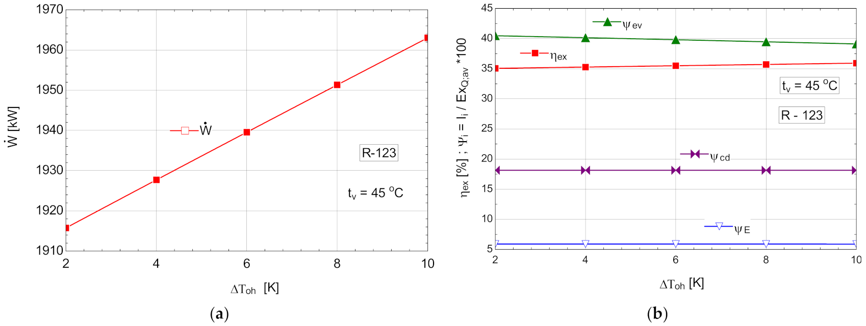
5.2.2. ORC Cycle Performance Study with Internal Recovery Heat Exchanger and Overheating with R123
The schematic of the system is shown in Figure 6.
Table 11.
Energetic and exergetic measures for the ORC with R-123, with internal recovery exchanger and overheating, .
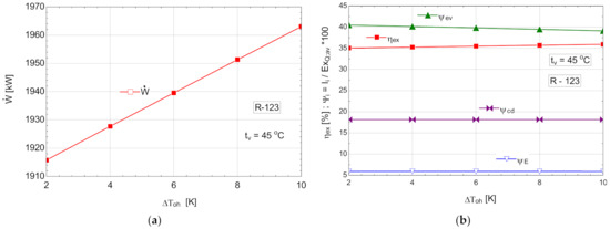
Figure 12.
ORC with R-123 with internal heat exchanger and overheating: (a) mechanical power, depending on the degree of overheating, ; (b) exergetic efficiency and weights of exergy destructions relative to the exergy of available recovered heat, depending on the variation of the degree of overheating, .
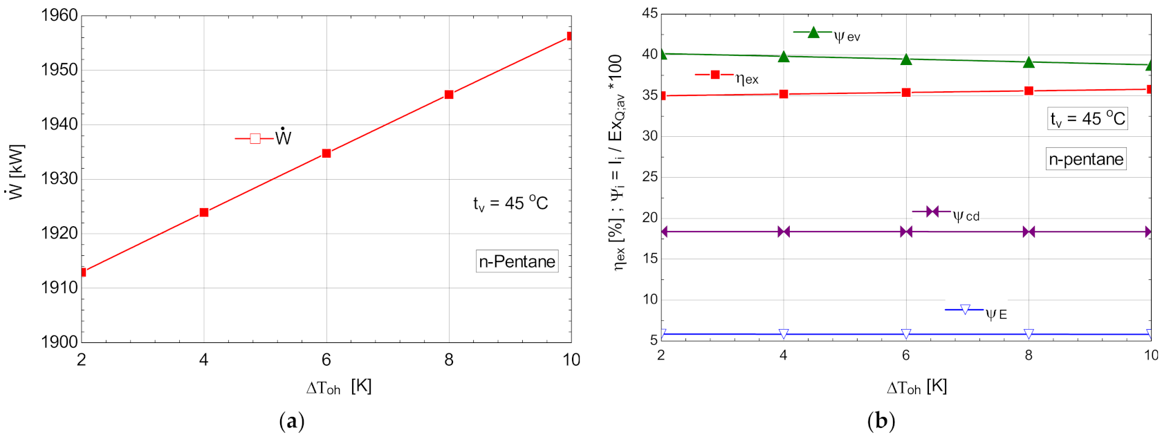
5.2.3. Performance Study for the ORC with Internal Recovery Heat Exchanger and Overheating, Operating with n-Pentane
The schematic of the system is shown in Figure 6.
Table 12.
Energetic and exergetic measures for the n-pentane ORC cycle, with internal recovery exchanger and overheating, .
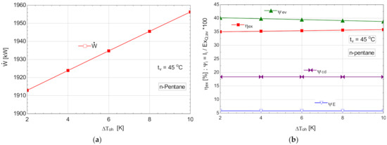
Figure 13.
ORC with n-pentane with internal heat exchanger and overheating; (a) mechanical power, depending on the degree of overheating, ; (b) exergetic efficiency and weights of exergy destructions relative to the exergy of available recovered heat, depending on the variation of the degree of overheating, .
5.2.4. Comparative Results on the Performance of Rankine Cycles Working with Different Organic Fluids
Under the conditions imposed by the recovery of the heat evacuated by the compression area of the cryogenic air separation unit and following the comparative study using different organic fluids, the following resulted (Table 13).
Table 13.
Performance parameters of ORC operating with different working fluids.
The final choice for the working fluid was conducted on a risk and economic analysis.
6. Conclusions
The exergetic analysis of the cryogenic air separation unit revealed an exergetic efficiency of the global system of 14%, and a share of the exergy loss with heat evacuated by the compressor cooling system of 21% of the total electricity consumption necessary to drive the compressors.
The loss of exergy in the compression area suggested, as a measure to increase the performance of the installation, the recovery of the heat transferred to the cooling system of the compressors and its transformation into mechanical energy with the help of ORC cycles.
To reduce the exergy destruction in the heat exchanger through which the ORC fluid absorbed heat from the compressed air stream (the ORC evaporator), an attempt was conducted to reduce the temperature difference between the air and the ORC fluid by increasing the temperature of the ORC fluid at the inlet to the heat exchanger. In this sense, the scheme of the ORC installation was structurally modified by adding an internal recuperative heat exchanger; the effect was to reduce the overall exergy destruction in the heat exchanger by decreasing the exergy destruction in the heating zone of the ORC fluid until the saturation temperature (vaporization temperature) was reached and the mechanical power produced was increased accordingly.
To further reduce the destruction of exergy caused by the large temperature difference between the compressed air and the ORC fluid, the organic fluid vapor was overheated. As expected, the perfection of the cycle represented by its exergetic efficiency improved. The effect of increasing the enthalpy fall in the expander due to overheating was tempered by the decrease in the mass flow rate, but overall, the produced mechanical power increased.
The conclusions drawn from the exergetic analysis of the behavior of the ORC cycle with R-245fa were extended to other organic fluids both in the category of those with a non-negative saturated vapor slope, and those in which the expansion in the expander reached the wetland. Investigations were conducted, based on an exergetic analysis of the operation of the cycle, as to which achieved the best results with R245fa (cycle with overheating and internal recuperative heat exchanger) in the case of operation with R123, n-pentane and R717.
For all organic agents, the increase in the vaporization temperature obviously led to an increase in the power produced by the ORC system. Unfortunately, the maximum value of the vaporization temperature was limited by the need to ensure a minimum temperature difference ( in the evaporator of the installation. The same issue occurred with the degree of overheating for a given evaporation temperature.
If R717 was used as a working agent, due to the expansion of the gas in the expander to the wet area, the internal recovery heat exchanger was missing from the diagram; this disadvantage was offset by the possibility of operating with a much higher degree of overheating than in the case of the other fluids studied, which had a non-negative saturated vapor curve slope.
Among the cases studied, the variant with R717 and with overheating achieved the highest mechanical power recovered from the heat evacuated by the compressed air, and the lowest mass flow rate of working fluid in the conditions of the best exergetic efficiency.
N-pentane was distinguished by low fluid flow and high mechanical power.
R123 had a much higher power than n-pentane but for a much higher organic fluid flow.
In addition to the thermodynamic analysis, a risk and economic analysis will tip the balance of the decision towards one of the analyzed ORCs working fluids.
Recovery of the heat evacuated when cooling the air in the compression area of the cryogenic air separation unit on the platform of the Galati Iron and Steel Works with the help of an ORC and its transformation into electricity is a viable solution. This can reduce the total electricity consumption for compressor drive by 6%.
Author Contributions
Conceptualization, C.I., S.B. and A.D.; methodology, C.D. and A.D.; software, S.B., C.I. and C.D.; validation, A.S., C.D. and A.D.; formal analysis, A.D. and A.S.; investigation, S.B. and C.D.; resources, C.I.; data curation, C.D.; writing—original draft preparation, S.B. and A.D; writing—review and editing, S.B., and A.S.; visualization, C.D and C.I.; supervision, A.D.; project administration, A.S.; funding acquisition, C.D. All authors have read and agreed to the published version of the manuscript.
Funding
This research was funded by the Romanian Ministry of Education and University Politehnica of Bucharest through the PubArt Program.
Conflicts of Interest
The authors declare no conflict of interest.
Nomenclature
| Cp | compressor |
| E | expander |
| current of electrical energy (exergy), kW | |
| current of exergy, kW | |
| Ev | evaporator |
| F | exergetic fuel, kW |
| current of gaseous nitrogen, kmol/s | |
| current of gaseous oxygen, kmol/s | |
| LAr | current of liquid argon, kmol/s |
| current of heat, kW | |
| P | pump, exergetic product, kW |
| mechanical power, kW | |
| current of thermo-mechanical exergy, kW | |
| current of chemical exergy, kW | |
| mass enthalpy, kJ/kg | |
| current of exergy destruction due to internal irreversibility, kW | |
| L | current of exergy loss, kW |
| mass flow rate, kg/s | |
| p | pressure, Pa |
| s | mass entropy, kJ/(kg K) |
| T | temperature, K |
| Subscripts | |
| 0 | environment, in equilibrium with the environment |
| a | air |
| av | available |
| c | condensation |
| Cd | condenser |
| cp | compressor |
| ev | evaporator |
| ex | exergetic |
| i | inlet |
| h | heating of the liquid in the evaporator (Table 9) |
| L | loss |
| o | outlet |
| oh | overheating |
| ORC | ORC fluid |
| P | pump, pinch |
| Q | heat |
| zev | evaporation zone in the evaporator (Table 9) |
| w | water |
| Superscript | |
| Cd | condenser |
| CH | chemical |
| T | thermodynamic temperature, K |
| TM | thermo-mechanical |
| TOT | total |
| Greek Symbols | |
| ε | heat exchanger efficiency |
| Ψ | share of an exergetic loss or destruction in the fuel consumption |
References
- Moran, M.J.; Shapiro, H.N.; Boettner, D.D.; Bailey, M.B. Fundamentals of Engineering Thermodynamics, 8th ed.; Wiley: New York, NY, USA, 2014; pp. 265–270, 445–450. [Google Scholar]
- Feng, Y.; Hung, T.; Zhang, Y.; Li, B.; Yang, J.; Shi, Y. Performance comparison of low-grade ORCs (organic Rankine cycles) using R245fa, pentane and their mixtures based on the thermoeconomic multi-objective optimization and decision makings. Energy 2015, 93, 2018–2029. [Google Scholar] [CrossRef]
- Wang, S.; Fu, Z. Thermodynamic Investigation of an Integrated Solar Combined Cycle with an ORC System. Entropy 2019, 21, 428. [Google Scholar] [CrossRef] [PubMed] [Green Version]
- Li, Y.; Tang, T. Configuration Selection of the Multi-Loop Organic Rankine Cycle for Recovering Energy from a Single Source. Entropy 2021, 23, 1435. [Google Scholar] [CrossRef] [PubMed]
- Brasz, L.J.; Bilbow, W.M. Ranking for working fluids for Organic Rankine Cycle applications. In Proceedings of the International Refrigeration and Air Conditioning Conference, West Lafayette, IN, USA, 12–15 July 2004. [Google Scholar]
- Yang, K.; Zhang, H.; Wang, E.; Song, S.; Bei, C.; Chang, Y.; Wang, H.; Yao, B. Study on Mixed Working Fluids with Different Compositions in Organic Rankine Cycle (ORC) Systems for Vehicle Diesel Engines. Entropy 2014, 16, 4769–4787. [Google Scholar] [CrossRef] [Green Version]
- Chavez, D.L.; Beltran-Chacon, R.; Cardenas-Terrazas, P.; Islas, S.; Velázquez, N. Design and Analysis of the Domestic Micro-Cogeneration Potential for an ORC System Adapted to a Solar Domestic Hot Water System. Entropy 2019, 21, 911. [Google Scholar] [CrossRef] [Green Version]
- Liu, B.T.; Chien, K.H.; Wang, C.C. Effect of working fluids on organic Rankine cycle for waste heat recovery. Energy 2004, 29, 1207–1217. [Google Scholar] [CrossRef]
- Bao, J.J.; Zhao, L. A review of working fluid and expander selections for organic Rankine cycle. Renew. Sustain. Energy Rev. 2013, 24, 325–342. [Google Scholar] [CrossRef]
- Dobrovicescu, A.; Grosu, L.; Queiros-Conde, D. Optimisation of a small solar organic Rankine cycle based on the exergetic analysis. Int. J. Exergy 2017, 22, 1–28. [Google Scholar] [CrossRef]
- Fontalvo, A.; Solano, J.; Pedraza, C.; Bula, A.; Quiroga, A.G.; Padilla, R.V. Energy, Exergy and Economic Evaluation Comparison of Small-Scale Single and Dual Pressure Organic Rankine Cycles Integrated with Low-Grade Heat Sources. Entropy 2017, 19, 476. [Google Scholar] [CrossRef] [Green Version]
- Tashtoush, B.; Morosuk, T.; Chudasama, J. Exergy and Exergoeconomic Analysis of a Cogeneration Hybrid Solar Organic Rankine Cycle with Ejector. Entropy 2020, 22, 702. [Google Scholar] [CrossRef]
- Ahmadi, M.H.; Sadaghiani, M.S.; Pourfayaz, F.; Ghazvini, M.; Mahian, O.; Mehrpooya, M.; Wongwises, S. Energy and Exergy Analyses of a Solid Oxide Fuel Cell-Gas Turbine-Organic Rankine Cycle Power Plant with Liquefied Natural Gas as Heat Sink. Entropy 2018, 20, 484. [Google Scholar] [CrossRef] [PubMed] [Green Version]
- Effatpanah, S.K.; Ahmadi, M.H.; Delbari, S.H.; Lorenzini, G. Energy, Exergy, Exergoeconomic and Emergy-Based Exergoeconomic (Emergoeconomic) Analyses of a Biomass Combustion Waste Heat Recovery Organic Rankine Cycle. Entropy 2022, 24, 209. [Google Scholar] [CrossRef] [PubMed]
- Shamoushaki, M.; Aliehyaei, M.; Rosen, M.A. Energy, Exergy, Exergoeconomic and Exergoenvironmental Impact Analyses and Optimization of Various Geothermal Power Cycle Configurations. Entropy 2021, 23, 1483. [Google Scholar] [CrossRef] [PubMed]
- Feng, Y.q.; Luo, Q.h.; Wang, Q.; Wang, S.; He, Z.x.; Zhang, W.; Wang, X.; An, Q.s. Entropy and Entransy Dissipation Analysis of a Basic Organic Rankine Cycles (ORCs) to Recover Low-Grade Waste Heat Using Mixture Working Fluids. Entropy 2018, 20, 818. [Google Scholar] [CrossRef] [Green Version]
- Cheng, X.T.; Liang, X.G. Entransy loss in thermodynamic processes and its application. Energy 2012, 44, 964–972. [Google Scholar] [CrossRef]
- Cheng, X.T.; Liang, X.G. Discussion on the entransy expressions of the thermodynamic laws and their applications. Energy 2013, 56, 46–51. [Google Scholar] [CrossRef]
- Li, T.L.; Fu, W.C.; Zhu, J.L. An integrated optimization for organic Rankine cycle based on entransy theory and thermodynamics. Energy 2014, 72, 561–573. [Google Scholar] [CrossRef]
- Liu, C.; He, C.; Gao, H.; Xu, X.; Xu, J. The Optimal Evaporation Temperature of Subcritical ORC Based on Second Law Efficiency for Waste Heat Recovery. Entropy 2012, 14, 491–504. [Google Scholar] [CrossRef] [Green Version]
- Lee, H.Y.; Kim, K.H. Energy and Exergy Analyses of a Combined Power Cycle Using the Organic Rankine Cycle and the Cold Energy of Liquefied Natural Gas. Entropy 2015, 17, 6412–6432. [Google Scholar] [CrossRef] [Green Version]
- Koc, Y.; Yagli, H.; Koc, A. Exergy Analysis and Performance Improvement of a Subcritical/Supercritical Organic Rankine Cycle (ORC) for Exhaust Gas Waste Heat Recovery in a Biogas Fuelled Combined Heat and Power (CHP) Engine Through the Use of Regeneration. Energies 2019, 12, 575. [Google Scholar] [CrossRef] [Green Version]
- Liu, G.; Wang, Q.; Xu, J.; Miao, Z. Exergy Analysis of Two-Stage Organic Rankine Cycle Power Generation System. Entropy 2021, 23, 43. [Google Scholar] [CrossRef] [PubMed]
- Fergani, Z.; Morosuk, T.; Touil, D. Exergy-Based Multi-Objective Optimization of an Organic Rankine Cycle with a Zeotropic Mixture. Entropy 2021, 23, 954. [Google Scholar] [CrossRef] [PubMed]
- Dorosz, P.; Wojcieszak, P.; Malecha, Z. Exergetic Analysis, Optimization and Comparison of LNG Cold Exergy Recovery Systems for Transportation. Entropy 2018, 20, 59. [Google Scholar] [CrossRef] [PubMed] [Green Version]
- Bucsa, S.; Serban, A.; Balan, M.C.; Ionita, C.; Nastase, G.; Dobre, C.; Dobrovicescu, A. Exergetic Analysis of a Cryogenic Air Separation Unit. Entropy 2022, 24, 272. [Google Scholar] [CrossRef] [PubMed]
- Latrash, F.; Agnew, B.; Al-Weshahi, M.A.; Eshoul, N.M. Optimal Selection of Using Fluids (HFC, HCFC, HFC)for an Organic Rankine Cycle Utilising a Low Temperature Geothermal Energy Source. In Proceedings of the 5th International Conference on Environment Science and Engineering, Volume 83 of IPCBEE, Istanbul, Turkey, 24–25 April 2015. [Google Scholar] [CrossRef]
- Chen, H.; Goswami, D.Y.; Stefanakos, E.K. A review of thermodynamic cycles and working fluids for the conversion of low-grade heat. Renew. Sustain. Energy Rev. 2010, 14, 3059–3067. [Google Scholar] [CrossRef]
- Heberle, F.; Brueggemann, D. Exergy based fluid selection for a geothermal Organic Rankine Cycle for combined heat and power generation. Appl. Therm. Eng. 2010, 30, 1326–1332. [Google Scholar] [CrossRef]
- Javanshir, A.; Sarunac, N.; Razzaghpanah, Z. Thermodynamic analysis of a regenerative organic Rankine cycle using dry fluids. Appl. Therm. Eng. 2017, 123, 852–864. [Google Scholar] [CrossRef]
- Aziz, F.; Mudasar, R.; Kim, M.H. Exergetic and heat load optimization of high temperature organic Rankine cycle. Energy Convers. Manag. 2018, 171, 48–58. [Google Scholar] [CrossRef]
- Abam, F.I.; Briggs, T.A.; Ekwe, B.E.; Kanu, C.G.; Effiom, S.O.; Ndukwu, M.C.; Ohunakin, S.O.; Ofem, M.I. Exergy analysis of a novel low-heat recovery organic Rankine cycle (ORC) for combined cooling and power generation. Energy Sources Part A-Recovery Util. Environ. Eff. 2019, 41, 1649–1662. [Google Scholar] [CrossRef]
- EES–Engineering Equation Solver. Available online: https://fchartsoftware.com/ees (accessed on 21 May 2022).
- Groniewsky, A.; Wagner, C. Investigation of the Effect of the Regenerative Heat Exchanger on the Performance of Organic Rankine Cycles Using Perturbed Chain-Statistical Associating Fluid Theory Equation of State. Ind. Eng. Chem. Res. 2020, 59, 19643–19656. [Google Scholar] [CrossRef]
- Landelle, A.; Tauveron, N.; Haberschill, P.; Revellin, R.; Colasson, S. Organic Rankine cycle design and performance comparison based on experimental database. Appl. Energy 2017, 204, 1172–1187. [Google Scholar] [CrossRef]
- Dai, Y.; Wang, J.; Lin, G. Parametric optimization and comparative study of organic Rankine cycle (ORC) for low grade waste heat recovery. Energy Convers. Manag. 2009, 50, 576–582. [Google Scholar] [CrossRef]


Publisher’s Note: MDPI stays neutral with regard to jurisdictional claims in published maps and institutional affiliations. |
© 2022 by the authors. Licensee MDPI, Basel, Switzerland. This article is an open access article distributed under the terms and conditions of the Creative Commons Attribution (CC BY) license (https://creativecommons.org/licenses/by/4.0/).