

Marginal Misfit of 3D-Printed (Selective Laser Sintered), CAD-CAM and Lost Wax Technique Cobalt Chromium Copings with Shoulder and Chamfer Finish Lines: An In-Vitro Study

 ,
,
Abstract
:1. Introduction
2. Materials and Methods
2.1. Ethical Considerations
2.2. Tooth Preparation
2.3. Study Groups (Table 1)

| Margin Type | Fabrication Technique | Study Groups |
|---|---|---|
| Shoulder (SH) | SLM | SH-SLM |
| CAD-CAM | SH-CAD-CAM | |
| CAST | SH-CAST | |
| Radial-Shoulder (R-SH) | SLM | R-SH-SLM |
| CAD-CAM | R-SH-CAD-CAM | |
| CAST | R-SH-CAST | |
| Chamfer (CH) | SLM | CH-SLM |
| CAD-CAM | CH-CAD-CAM | |
| CAST | CH-CAST |
2.4. Coping Preparation
2.5. CAD-CAM
2.6. Selective Laser Melting (SLM)
2.7. Lost Wax Technique (LWT)
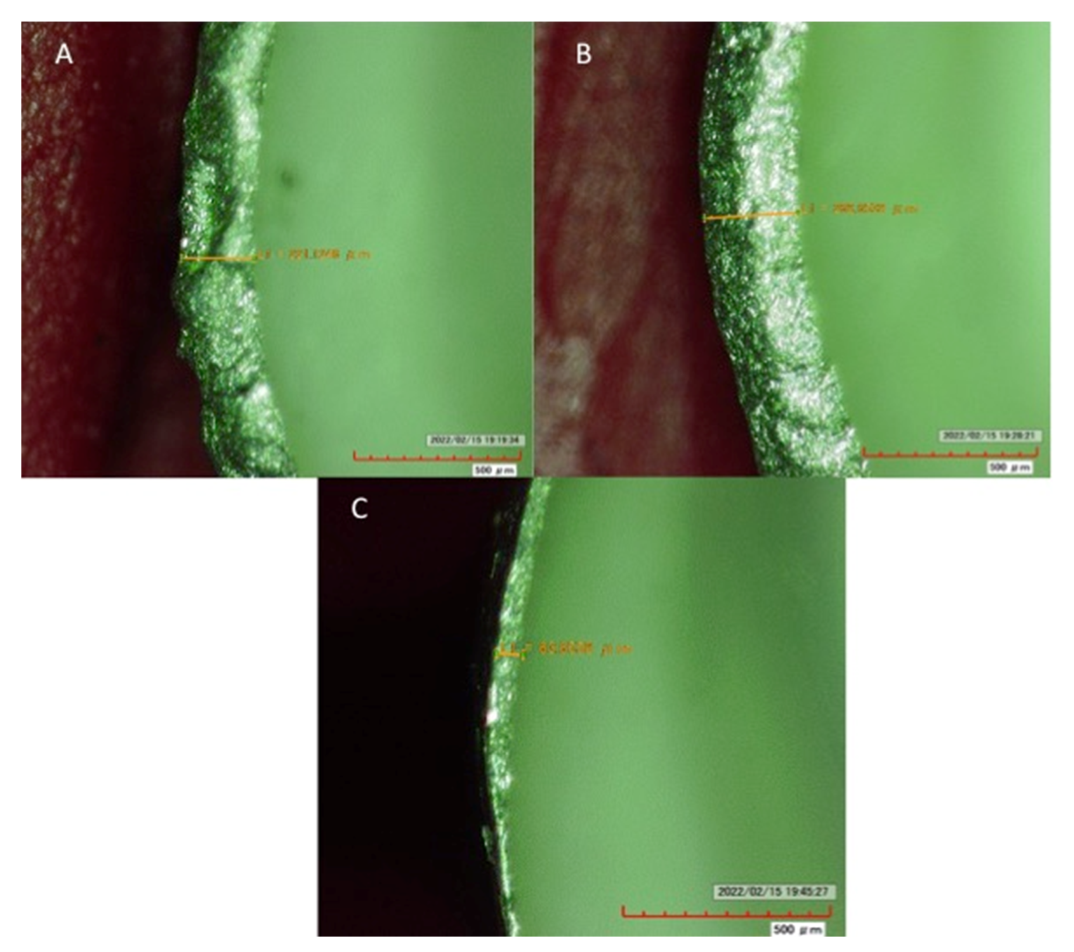
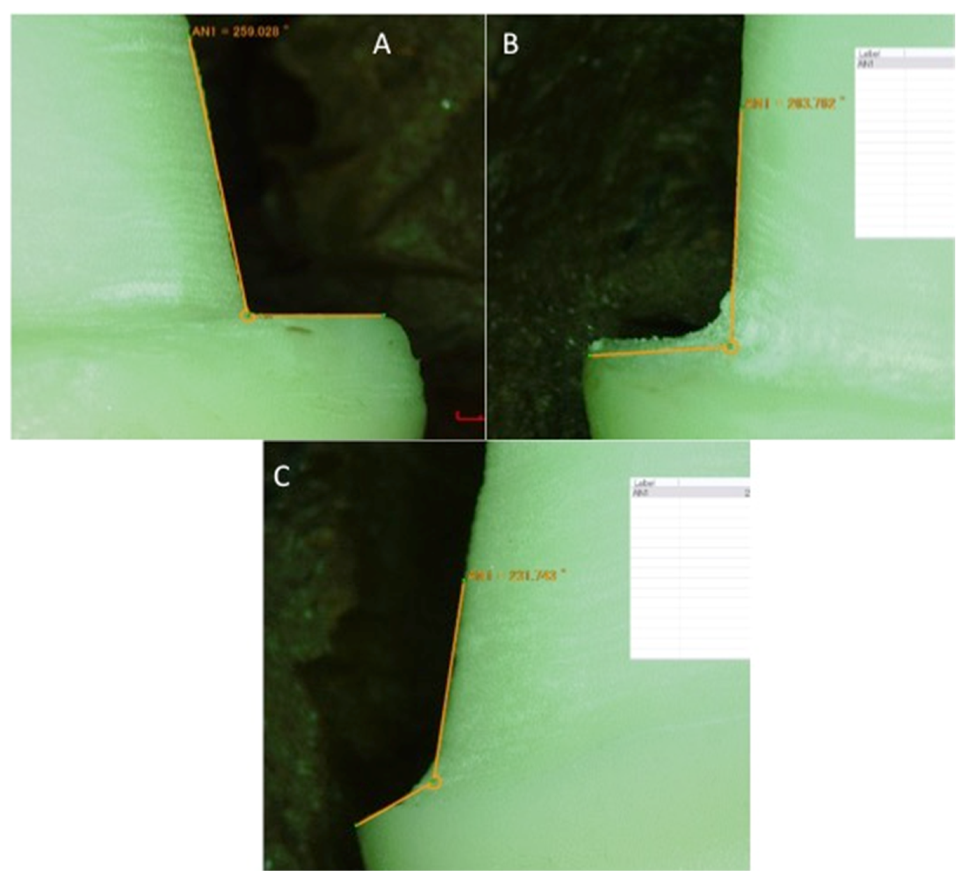
2.8. Assessment of Marginal Misfit
2.9. Statistical Analysis
3. Results
4. Discussion
5. Conclusions
Author Contributions
Funding
Institutional Review Board Statement
Informed Consent Statement
Data Availability Statement
Acknowledgments
Conflicts of Interest
References
- Alqahtani, A.S.; AlFadda, A.M.; Aldasouki, M.H.; Alnuwaiser, M.K.; Al-Saleh, S.; Alresayes, S.; Alshahrani, A.; Vohra, F.; Abduljabbar, T. Comparison of Marginal Integrity and Surface Roughness of Selective Laser Melting, CAD-CAM and Digital Light Processing Manufactured Co-Cr Alloy Copings. Appl. Sci. 2021, 11, 8328. [Google Scholar] [CrossRef]
- Vohra, F.; Ismail, I.H.; Abduljabbar, T.; Ali, M.; Basunbul, G.I.; Al-Hamdan, R.S.; Hasan, M.I. Influence of Veneer Thickness, Coping Thickness and Veneer-Coping Ratio on the Fracture Toughness of Ceramic Layered Metal and Zirconium Crowns. J. Biomater. Tissue Eng. 2018, 8, 1364–1369. [Google Scholar] [CrossRef]
- Bin-Shuwaish, M.; AlFawaz, Y.F.; AlGamaiah, H.A.; AlSani, A.S.; Abobakr, I.B.; Alzahrani, K.M.; Almutairi, B.; Attar, E.A.; Vohra, F.; Abduljabbar, T. Technical accuracy of dental laboratories in the quality and shade matching of porcelain fused to metal crowns: An in vitro study. Int. J. Environ. Res. Public Health 2021, 18, 2722. [Google Scholar] [CrossRef] [PubMed]
- Samer, M.S.; Faraz, Q.; Al-Dubai, S.A.; Vohra, F.; Abdullah, H.; Taiyeb-Ali, T.B.; Saub, R. Clinical outcomes and predictors of satisfaction in patients with improved lithium disilicate all-ceramic crowns. Med. Princ. Pract. 2017, 26, 470–479. [Google Scholar] [CrossRef]
- Mansour, F.K.; Ibrahim, R.M.; Mansour, H.; Hamdy, A.M. Assessment of internal fit and micro leakage of conventionally fabricated ceramometallic restoration versus CAD wax and press veneering (in-vitro study). BDJ Open 2021, 7, 17. [Google Scholar] [CrossRef]
- Al-Aali, K.A.; Alhamdan, R.S.; Maawadh, A.M.; Vohra, F.; Abduljabbar, T. Influence of contemporary CAD-CAM milling systems on the fit and adaptation of partially stabilized Zirconia fixed partial dentures. Pak. J. Med. Sci. 2021, 37, 45. [Google Scholar] [CrossRef]
- Al-Aali, K.A.; Alresayes, S.; Alhenaki, A.M.; Vohra, F.; Abduljabbar, T. Influence of time and hydration (ageing) on flexural strength of Yttrium stabilized Zirconia polycrystals (Y-TZP) fabricated with different CAD-CAM Systems. Pak. J. Med. Sci. 2021, 37, 833. [Google Scholar] [CrossRef]
- Park, J.Y.; Kim, H.Y.; Kim, J.H.; Kim, J.H.; Kim, W.C. Comparison of prosthetic models produced by traditional and additive manufacturing methods. J. Adv. Prosthodont. 2015, 7, 294–302. [Google Scholar] [CrossRef]
- Gap, M. The accuracy of fit of crowns made from wax patterns produced conventionally (hand formed) and via CAD/CAM technology. J. Prosthodont. Restor. Dent. 2016, 24, 7–10. [Google Scholar]
- Prabhu, R.; Prabhu, G.; Baskaran, E.; Arumugam, E.M. Clinical acceptability of metal ceramic fixed partial dental prosthesis fabricated with direct metal laser sintering technique—5 year follow-up. J. Indian Prosthodont. Soc. 2016, 16, 193–197. [Google Scholar] [CrossRef] [PubMed]
- Al-Aali, K.A.; Bin-Shuwaish, M.S.; Alhenaki, A.M.; Al Ahdal, K.; Al Deeb, L.; Maawadh, A.M.; AlHelal, A.; Alshehri, H.; Vohra, F.; Abduljabbar, T. Influence of milling systems and marginal configurations on the fit of yttrium stabilized tetragonal zirconia polycrystals (Y-TZP)’copings. J. Appl. Biomater. Funct. Mater. 2020, 18, 2280800020924514. [Google Scholar] [CrossRef] [PubMed]
- Van Noort, R. The future of dental devices is digital. Dent. Mater. 2012, 28, 3–12. [Google Scholar] [CrossRef] [PubMed]
- Fernandez, M.; Delgado, L.; Molmeneu, M.; Garcia, D.; Rodriguez, D. Analysis of the misfit of dental implant-supported prostheses made with three manufacturing processes. J. Prosthet. Dent. 2014, 111, 116–123. [Google Scholar] [CrossRef] [PubMed]
- Aonso-Pérez, R.; Bartolomé, J.F.; Ferreiroa, A.; Salido, M.P.; Pradíes, G. Evaluation of the Mechanical Behavior and Marginal Accuracy of Stock and Laser-Sintered Implant Abutments. Int. J. Prosthodont. 2017, 30, 136–138. [Google Scholar] [CrossRef]
- Huang, Z.; Zhang, L.; Zhu, J.; Zhang, X. Clinical marginal and internal fit of metal ceramic crowns fabricated with a selective laser melting technology. J. Prosthet. Dent. 2015, 113, 623–627. [Google Scholar] [CrossRef]
- Örtorp, A.; Jönsson, D.; Mouhsen, A.; Vult von Steyern, P. The fit of cobalt-chromium three-unit fixed dental prostheses fabricated with four different techniques: A comparative in vitro study. Dent. Mater. 2011, 27, 356–363. [Google Scholar] [CrossRef]
- Castillo-oyagüe, R.; Lynch, C.D.; Turrión, A.S.; López-lozano, J.F.; Torres-lagares, D.; Suárez-garcía, M.J. Misfit and microleakage of implant-supported crown copings obtained by laser sintering and casting techniques, luted with glass-ionomer, resin cements and acrylic/urethane-based agents. J. Dent. 2013, 41, 90–96. [Google Scholar] [CrossRef]
- Bibb, R.; Eggbeer, D.; Williams, R. Rapid manufacture of removable partial denture frameworks. Rapid Prototyp. J. 2006, 12, 95–99. [Google Scholar] [CrossRef]
- Bilgin, M.S.; Erdem, A.; Dilber, E.; Ersoy, İ. Comparison of fracture resistance between cast, CAD/CAM milling, and direct metal laser sintering metal post systems. J. Prosthodont. Res. 2016, 60, 23–28. [Google Scholar] [CrossRef]
- Kim, K.B.; Kim, W.C.; Kim, H.Y.; Kim, J.H. An evaluation of marginal fit of three-unit fixed dental prostheses fabricated by direct metal laser sintering system. Dent. Mater. 2013, 29, e91–e96. [Google Scholar] [CrossRef]
- Shillingburg, H.T., Jr.; Hobo, S.; Fisher, D.W. Preparation design and margin distortion in porcelain-fused-to-metal restorations. J. Prosthet. Dent. 1973, 29, 276–284. [Google Scholar] [CrossRef]
- Faucher, R.R.; Nicholls, J.I. Distortion related to margin design in porcelainfused- to-metal restorations. J. Prosthet. Dent. 1980, 43, 149–155. [Google Scholar] [CrossRef]
- Omar, R. Scanning electron microscopy of the marginal fit of ceramometal restorations with facially butted porcelain margins. J. Prosthet. Dent. 1987, 58, 13–19. [Google Scholar] [CrossRef]
- Al Maaz, A.; Thompson, G.A.; Drago, C.; An, H.; Berzins, D. Effect of finish line design and metal alloy on the marginal and internal gaps of selective laser melting printed copings. J. Prosthet. Dent. 2019, 122, 143–151. [Google Scholar] [CrossRef] [PubMed]
- Al Rifaiy, M.Q. Evaluation of vertical marginal adaptation of provisional crowns by digital microscope. Niger. J. Clin. Pract. 2017, 20, 1610–1617. [Google Scholar] [CrossRef]
- Christensen, G.J. Marginal fit of gold inlay castings. J. Prosth. Dent. 1966, 16, 297–305. [Google Scholar] [CrossRef]
- Association, A.D. ANSI/ADA Specification No. 8 for zinc phosphate cement. In Guide to Dental Materials and Devices, 5th ed.; American Dental Association: Chicago, IL, USA. [CrossRef]
- McLean, J.W.; von Fraunhofer, J.A. The estimation of cement film thickness by an in vivo technique. Br. Dent. J. 1971, 131, 107–111. [Google Scholar] [CrossRef]
- Boening, K.W.; Walter, M.H.; Reppel, P.D. Non-cast titanium restorations in fixed prosthodontics. J. Oral Rehabil. 1992, 19, 281–287. [Google Scholar] [CrossRef]
- Li, P.; Warner, D.H.; Fatemi, A.; Phan, N. Critical assessment of the fatigue performance of additively manufactured Ti–6Al–4V and perspective for future research. Int. J. Fatigue 2016, 85, 130–143. [Google Scholar] [CrossRef]
- Ansarifard, E.; Farzin, M.; Parlack, A.Z.; Taghva, M.; Zare, R. Comparing Castability of Nickel-Chromium, Cobalt-Chromium, and Non-Precious Gold Color Alloys, Using two Different Casting Techniques. J. Dent. 2022, 23, 7. [Google Scholar]
- Pascoe, D.F. Analysis of the geometry of finishing lines for full crown restorations. J. Prosthet. Dent. 1978, 40, 157. [Google Scholar] [CrossRef]
- Gavelis, J.R.; Morency, J.D.; Riley, E.D.; Sozeio, R.B. The effect of various finish line preparations on the marginal seal and occlusal seat of full crown preparations. J. Prosthet. Dent. 1981, 45, 138–145. [Google Scholar] [CrossRef]
- Gavelis, J.R.; Morency, J.D.; Riley, E.D.; Sozeio, R.B. The effect of various finish line preparations on the marginal seal and occlusal seat of full crown preparations. J. Prosthet. Dent. 2004, 92, 1–7. [Google Scholar] [CrossRef] [PubMed]


| Margin Type | SLM | p-Value * | CAD-CAM | p-Value * | LWT | p-Value * |
|---|---|---|---|---|---|---|
| Mean (SD) (μm) | Mean (SD) (μm) | Mean (SD) (μm) | ||||
| Shoulder (SH) | 105.20 (26.22) a A | <0.01 | 68.64 (14.10) a B | <0.01 | 124.81 (22.0) a C | <0.01 |
| Radial Shoulder (R-SH) | 166.96 (27.68) b A | 58.80 (12.53) a B | 161.62 (29.44) b A | |||
| Chamfer (CH) | 167.96 (24.1) b A | 102.71 (18.01) b B | 163.3 | |||
| (27.57) b A |
| Margin Type | SLM | p-Value * | CAD-CAM | p-Value * | LWT | p-Value * |
|---|---|---|---|---|---|---|
| Mean (SD) (μm) | Mean (SD) (μm) | Mean (SD) (μm) | ||||
| Shoulder (SH) | 137.94 | <0.05 | 135.00 (13.56) a A | <0.05 | 100.00 (13.19) a a B | 0.09 |
| (37.85) a A | 93.93 (17.13) a B | |||||
| Radial Shoulder (R-SH) | 133.39 (20.87) ab A | 114.91 (15.29) ab AB | 89.38 | |||
| Chamfer (CH) | 116.71 (27.67) b A | 95.31 (18.31) b AB | (14.81) a B |
Publisher’s Note: MDPI stays neutral with regard to jurisdictional claims in published maps and institutional affiliations. |
© 2022 by the authors. Licensee MDPI, Basel, Switzerland. This article is an open access article distributed under the terms and conditions of the Creative Commons Attribution (CC BY) license (https://creativecommons.org/licenses/by/4.0/).
Share and Cite
Al-Saleh, S.; Vohra, F.; Albogami, S.M.; Alkhammash, N.M.; Alnashwan, M.A.; Almutairi, N.S.; Aali, K.A.; Alrabiah, M.; Abduljabbar, T. Marginal Misfit of 3D-Printed (Selective Laser Sintered), CAD-CAM and Lost Wax Technique Cobalt Chromium Copings with Shoulder and Chamfer Finish Lines: An In-Vitro Study. Medicina 2022, 58, 1313. https://doi.org/10.3390/medicina58101313
Al-Saleh S, Vohra F, Albogami SM, Alkhammash NM, Alnashwan MA, Almutairi NS, Aali KA, Alrabiah M, Abduljabbar T. Marginal Misfit of 3D-Printed (Selective Laser Sintered), CAD-CAM and Lost Wax Technique Cobalt Chromium Copings with Shoulder and Chamfer Finish Lines: An In-Vitro Study. Medicina. 2022; 58(10):1313. https://doi.org/10.3390/medicina58101313
Chicago/Turabian StyleAl-Saleh, Samar, Fahim Vohra, Shabab M. Albogami, Nawaf M. Alkhammash, Mohammed A. Alnashwan, Naif S. Almutairi, Khalid A. Aali, Mohammed Alrabiah, and Tariq Abduljabbar. 2022. "Marginal Misfit of 3D-Printed (Selective Laser Sintered), CAD-CAM and Lost Wax Technique Cobalt Chromium Copings with Shoulder and Chamfer Finish Lines: An In-Vitro Study" Medicina 58, no. 10: 1313. https://doi.org/10.3390/medicina58101313
APA StyleAl-Saleh, S., Vohra, F., Albogami, S. M., Alkhammash, N. M., Alnashwan, M. A., Almutairi, N. S., Aali, K. A., Alrabiah, M., & Abduljabbar, T. (2022). Marginal Misfit of 3D-Printed (Selective Laser Sintered), CAD-CAM and Lost Wax Technique Cobalt Chromium Copings with Shoulder and Chamfer Finish Lines: An In-Vitro Study. Medicina, 58(10), 1313. https://doi.org/10.3390/medicina58101313