1. Introduction
Concentrating solar power (CSP) and, in particular, parabolic trough collectors operating with oil as the heat transfer fluid (HTF) seems to have achieved the degree of technical maturity [
1] to allow commercial exploitation [
2]. Nevertheless, its energy generation cost has become a major barrier for its deployment without external financial support [
3], either in the form of subsidies or feed-in tariffs [
4]. The integrating of solar energy with conventional power plants or other power systems is an effective way to utilize solar energy and achieve fuel savings for power plant [
5]. A higher solar efficiency can be obtained with solar-aided power generation (SAPG) than with solar only ones [
6], and hybrid plants can use smaller solar fields, hence reducing the investment costs [
7,
8]. Typical values of energetic efficiency and land area for different types of parabolic trough solar-only plants can be found in [
9].
These advantages have yielded a number of studies on the matter, reviewed in [
10]. In [
11], a comparison is made between several topologies of hybrid plants, including solar fields with storage. Combined cycles (CC) operate in a broad range of temperatures and, thus allow integrating a wide variety of solar technologies [
12], from solar air towers [
13] to Fresnel collectors. Many studies focus on hybridization in the bottoming cycle, generally a subcritical water-steam Rankine, because the most developed solar technologies adapt better to its usual temperature range, in particular parabolic troughs with oil as HTF and Fresnel-type collectors. With generally poorer performance, the latter has a lower cost than the former [
14], and thus, it has been assessed; for example [
15] compares three options to re-power a steam power plant by hybridization with Fresnel collectors. Another example is [
16], in which a combined cycle is re-powered by integrating with a Fresnel collector field for feedwater heating and low pressure steam generation.
Integration with parabolic troughs using oil as HTF has been extensively studied over the last few years. The Yadz plant in Iran is analyzed exergetically in [
17]. It is a combined cycle formed by two Brayton cycles and a water/steam two-pressure Rankine cycle, combined in a post-combustion heat recovery steam generator (HRSG). The solar field uses parabolic troughs with oil as the heat transfer fluid (HTF) and is integrated at the high-pressure stages of the HRSG. The plant operates without post-combustion whenever there is sufficient solar radiation for the solar field to operate.
The hybridization of a number of CC plants ranging from 200 to 1000 MW, using the solar field for feedwater heating at different points of the bottoming cycle are compared in [
18]. The potential performance of medium and low temperature hybridization in a 200 MW coal plant has been studied in [
5], rendering high values of solar electric efficiency. The same conclusion has been obtained in [
19], a study of an integrated CC plant, which compares using solar energy for feedwater preheating against using it for periodical flue gas reheating at the HRSG.
Integrated CC plants are also being studied from the point of view of optimization. The Yadz plant in Iran is studied in [
20], in which the role of every element in the plant is classified as either fuel, product or loss, assigned a certain cost and then combined in a cost function, which is minimized using a genetic algorithm. The results improve the production costs of the plant and its exergetic efficiency.
Hybrid plants are either studied in power boosting mode (PBM) or fuel saving mode (FSM) [
18]. PBM considers the case of having a power plant produce more power, either by re-powering the steam turbine or by making it work off-nominal. Large solar contributions may lead either to having the turbine operate far from nominal or to having large turbines. Both cases could mean having to operate the turbine part load for large periods, thus losing efficiency and eventually neutralizing the gain derived from having a solar field. This is why [
19] considers that solar fields should be sized in the range 60–140 MW
th. Most of the studies are carried out from a PBM perspective.
However, in the current energetic scenario, it is interesting to study the possibility of making an existing plant consume less fuel by integrating a relatively small solar field (FSM). Apart from the savings in cost, this also would entail lower CO2 emissions. This paper presents a basic approach to a fuel saving problem. A generic ≈ 400 MW combined cycle plant with three pressure levels at the bottoming cycle, working with post-combustion at the HRSG will be taken as the base case being hybridized. During operation, post-combustion will be substituted for an energy input from a solar field, which will be used for generating steam, whenever there exists sufficient solar radiation. Three alternative hybrid configurations will be studied, all at the HRSG: parabolic trough collectors integrated at intermediate and low cycle pressures and Fresnel collectors integrated at low cycle pressure. The same solar energy input will be considered in the three cases in order to be able to compare them on an equal basis.
The operation of the plant will be extended throughout a year for annual results. For this, it will be assumed that the plant will function at nominal conditions 24 h a day, as a baseload plant. Hybrid operation will be assumed for a number of hours, and the rest will be assumed as fuel-only operation. The yearly savings in fuel, cost and emissions will be estimated. With these results, it is intended to compare three basic schemes of integration that could be implemented on an existing conventional plant, on two basic grounds: the point of integration, either intermediate or low cycle pressure, and solar technology, either parabolic trough or Fresnel. The aim is to obtain a criterion about the benefit of integrating an existing plant for FSM, because any significant differences between the three alternatives should show in this study.
2. Case Setting
The case setting for the study is based on the following points:
Having an equal solar energy contribution in the three cases to be compared is not a common approach; however, it has some importance. The available size for the solar field and the investment costs are common design constraints. Thus, it is interesting to study how the three alternatives perform with a fixed field size.
3. Plant Topology and Integration
The plant diagram of
Figure 1 shows a Brayton cycle coupled to a three pressure level Rankine water-steam cycle by a heat recovery steam generator (HRSG), which has a fuel input for post-combustion, as the original in [
21].
The original HRSG has been modified so that part of the water of the bottoming cycle can be diverted to a heat exchanger, where it will be heated by the heat transfer fluid (HTF) of the solar field. For hybridization alternative SF1, this will be done at intermediate cycle pressure and for SF2 and 3 at low pressure. The arrangement is represented in
Figure 1. It is the same integration philosophy used in [
17], and detailed more in [
20].
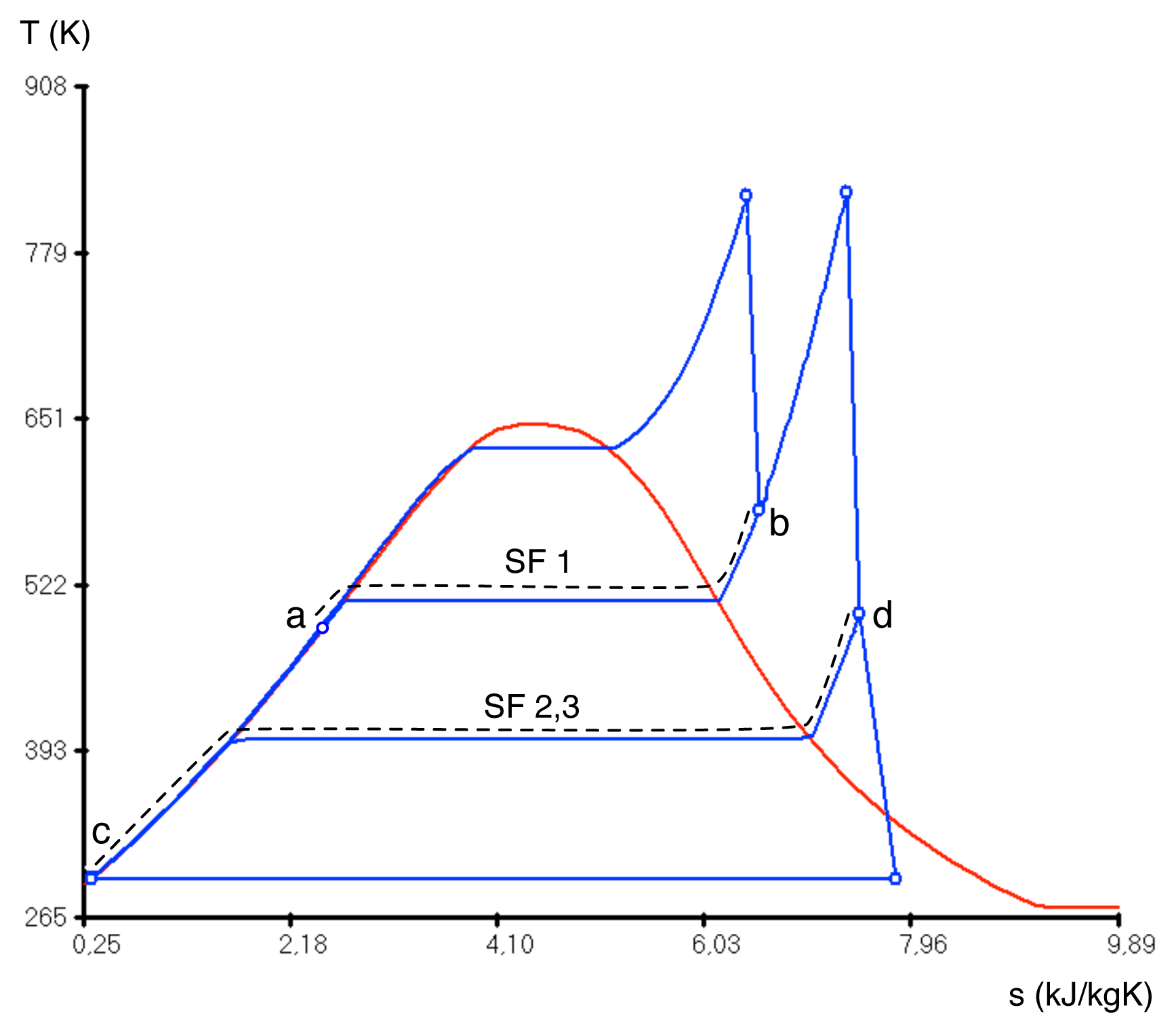
The enthalpy of the exhaust gases of the gas turbine is not enough to achieve nominal conditions in the Rankine cycle. Post-combustion will be used to supply the difference during nights and the hours of scarce solar resource, and it will be turned off in the hours when the solar field is operational. The bottoming cycle of the plant and the points of hybridization are represented in
Figure 2.
3.1. Combined Cycle
The basic parameters of the combined cycle are shown in
Table 1. The Brayton cycle is equal to the original one in [
21]. It produces 249.64 MW
e with a gas turbine operating between an inlet temperature of 1227.81 °C and an outlet temperature of 583.92 °C, with a pressure ratio of 17.12. The stack leaves the HRSG at 81.88 °C. In climate zones with good solar radiation, the condenser pressure that has been assumed here could prove exceedingly low to achieve in practice. However, this value has been taken in order to preserve the traceability to the original cycle [
21]. We shall assume that these values remain unaltered in the study.
The Rankine cycle is scaled from the original 129.48 MW
e in [
21] to 151.91 MW
e. The difference in power is either obtained from post-combustion in the HRSG or from the solar contribution.
As has been mentioned, the way of integrating the solar field with the combined cycle is the same as in [
17]: when there exists sufficient solar resource, part of the water flow of the HRSG is diverted to a water-HTF heat exchanger (see
Figure 1). The mass flow is calculated so that the cycle of
Figure 2 remains unaltered, equal to when operating with fuel only, and so that the solar field always delivers an equal 54.8 MW
th.
3.2. Solar Field
The data considered for thermal and exergetic efficiency for the receptor + collector groups are taken from
Table 2. It must be remarked that these values are for nominal operation and, therefore, higher than the ones found in [
17], which are weighed to account for yearly non-operation or off-nominal operation hours.
3.2.2. Parabolic Trough and Fresnel Collectors at Low Pressure, SF2, 3
For SF2, 3, the HTF operates in the range: 240 and 150 °C. At the SF2, 3 pressure, water saturates at 130.42 °C, where most part of the heat exchange will take place.
We shall assume that both parabolic trough (SF2) and Fresnel (SF3) implement the same thermodynamic cycle. The differences between them will show in the costs associated with achieving this performance with either technology.
4. Plant Performance Comparison
The simulations have been carried out with CicloGraf, a simulation software developed by the TAIIResearch Group, specifically built for thermodynamic process-engineering. Thermoflex [
24] has been used for the HTF-water/steam heat transfer simulations.
The energetic and exergetic results of the simulations are shown in
Table 3. These results allow calculating the overall efficiencies of the four modes of operation, shown in
Table 4, which are defined as follows:
The denominator of
ηth is the sum of the enthalpy of the fuel and the enthalpy of the solar radiation, thus the total enthalpy input to the plant. The definition of
ηex is different from others found in the literature, including [
21], which excluded the losses in the condenser and in the stack from the denominator, leading to higher values.
Regarding the performance of the plant in fuel mode compared to any of the solar modes, three points can be observed. The pumping power of the solar field reaches approximately 0.55 MW, comparable to the rest of the Rankine cycle. Larger fields would imply larger power and, thus, a certain impact on the overall efficiency. This practical remark adds to the discussion about the sizing of solar fields for hybrid plants in [
19].
The global energetic efficiency of the plant is lower in any solar mode than in fuel mode. It reaches ηth = 0.544 operating on fuel, while the highest of the solar modes, SF2, yields ηth = 0.539. The situation is reversed in exergy, where all solar modes of operation have greater exergetic efficiency.
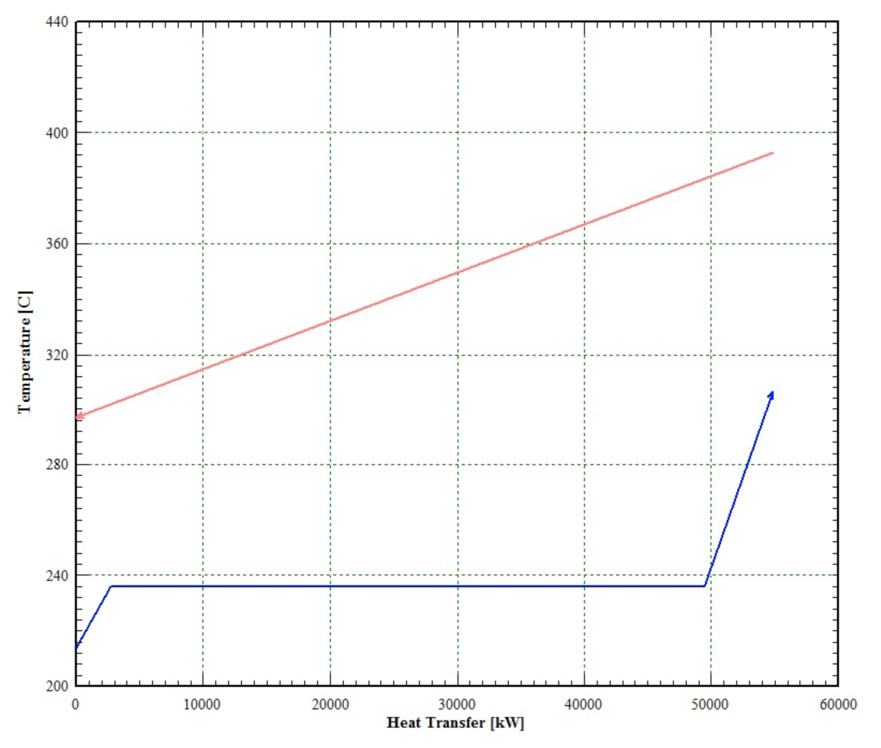
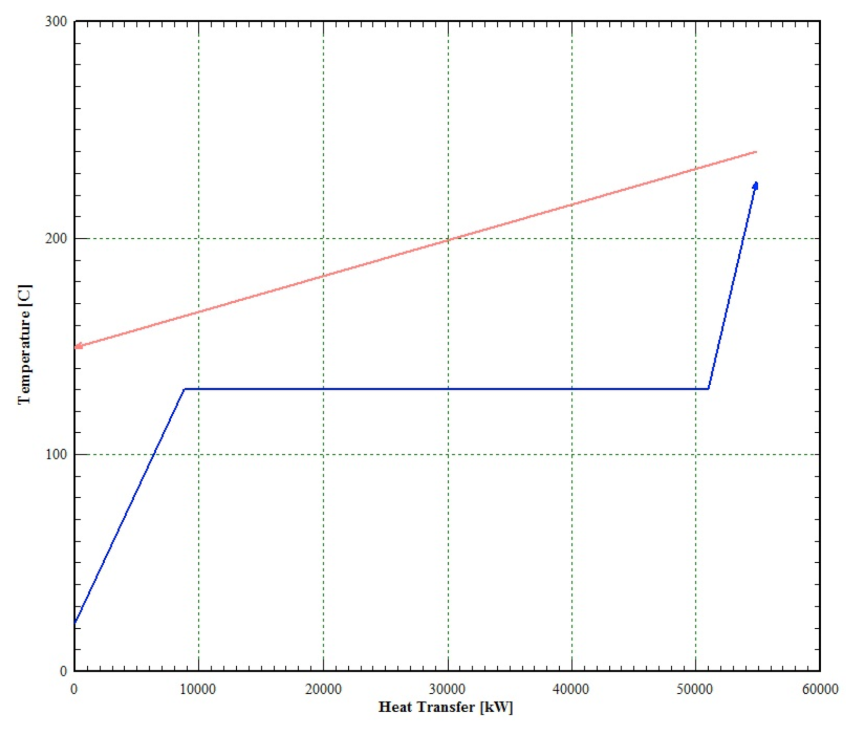
This is due to the fact that, when operating in any solar mode, only heat transfers take place at the HRSG, between the combustion gases from the Brayton and cycle water, and between the solar HTF and cycle water. In fuel mode, the former takes place equally, but the latter is exchanged for the combustion reaction at the post-combustor. In the HTF-cycle water transfer, the cause for irreversibility is the temperature drop between the flows, which might be large (see
Figures 3 and
4). However, the irreversibility in the post-combustor is significantly larger, first because of the chemical reaction itself, second because the temperature drop between the product gases and the cycle water is also larger.
It is also interesting to observe the high values of solar-electric efficiency obtained, 25.4 and 23.9%. These values are the ratio between the extra electric power generated due to either the post-combustion or the solar field, namely 22.43 MW, and the solar enthalpy input in each case. The results are in line with other studies that can be found in the literature, for example the 300 MW subcritical case in [
18] and integration scheme 2 of a 200 MW plant in [
5].
Finally, it is worth mentioning that in economic terms, the lower energetic efficiencies of the solar modes would not be relevant, because the solar resource is free of cost. It is then illustrating to consider the ratio between the power produced and the enthalpy of the fuel (excluding the solar resource): for the fuel-only mode; it is 0.54. It becomes 0.61 in the hybrid modes. We shall see the full economic repercussion of this in Section 5.
5. Economical Study and Operating Cycle of the Plant
We have assumed that our solar field will have a capacity factor (CF) of 2130 h/year, which is a reasonable value for a case in which the block of power is driven by the fossil source, therefore less affected by the minimum technical power that is required by an only-solar plant when operating at partial load.
Table 5 shows the one-year fuel balance and the savings in solar mode against 24-hour, fuel-only operation. The savings is approximately 2% of the total fuel-only consumption, which corresponds to 0.13 TWh. In terms of CO
2 released to the atmosphere by methane combustion, 26,724 tons of CO
2 per year are avoided assuming a gas production
versus thermal energy of 204 kgCO
2/kWh [
25].
In our economic analysis, we assume that the thermal plant is operating either with the post-combustion booster in the HRSG working in complementary mode with the solar field. Therefore, the cost of the combined cycle part remains the same, and the solar field implies an added capital cost that should be amortized by the fuel savings that is produced when operating with solar heat.
In our estimations, the fuel savings is evaluated in terms of primary heat provided by the solar field. The enthalpy given to the thermodynamic cycle by the solar field is fixed to a nominal value of 54.83 MW. Taking into account losses in the HTF-steam heat exchanging, the enthalpy of the heat transfer fluid through the solar field should be 61.82MW. The collector efficiencies have been evaluated for each collector technology, given a required solar irradiation power of 88.31 MW for configuration SF1, 83.54 MW for SF2 and 87.07 MW for SF3. The direct normal irradiation (DNI) for the nominal design of the solar field will depend on the location of the plant. In our case, with a DNI of 850 W/m
2, a reasonable design value in a favorable latitude (DNI
> 1800 kWh/y-m
2), the required solar field for each technology is shown in
Table 6, being of the order of 10 Ha (100,000 m
2).
The cost of the solar field has been evaluated by the following relation:
in which Cs is the required inversion in the solar field, calculated from the cost of the solar collectors (Ca), referring to their field aperture (Ac), and the cost of other equipment, such as instrumentation and control or heat exchangers.
The solar savings is evaluated taking into account the cost of the heat from natural gas that was not consumed, keeping the production and, therefore, the revenues due to electric energy selling. The solar savings is evaluated as:
with S
s the accumulated solar saving, S
p is the annual solar heat produced, equal to the natural gas savings, the cost of which C
ng. This cost and the operation and maintenance cost (C
O&M) have an incremental rate of i
ng and i
O&M as a consequence of the inflation rate of the fuel and the increase of labor and spare parts. C
l is the loan cost, that is a fixed cost in nominal value. Every cost is expressed in terms of present worth applying a d discount rate. A brief summary of the values for the main economic parameters is shown in
Table 7.
In our economic analysis, we have assumed that the solar projects are fully financed, that means the full installation cost (Cs) is financed by a loan at an interest rate (il) of 6% during 20 years (n). The loan cost (Cl) is expressed by the well-known formula:
The time at which the accumulated solar savings reach the initial investment cost gives the amortization time. In our case, this time corresponds to the moment in which the solar savings (Ss) reaches 50.82, 48.32 and 28.97 million Euros for the configurations SF1, SF2 and SF3, respectively.
Our estimation of the amortization time, with the economic variables shown in
Table 7, leads to eight years in the most favorable case of the SF3 configuration, in which Fresnel technology is used to feed the HSRG at low pressure. The application of trough technology increases the amortization time to 13 and 14 years for the configurations SF2 and SF1.
6. Conclusions
An integrated solar combined cycle (ISCCS) has been studied thermoeconomically from a fuel savings perspective. The objectives have been to compare the performance of integrating at intermediate and low pressure levels of the bottoming cycle, on one side, and to compare parabolic trough and Fresnel collector technologies, on the other. The conclusions of the study might be relevant to decide which alternative could be best to hybridize an existing CC plant.
Integrating an existing combined cycle with a solar field is advantageous, both from the point of view of the CC and from the point of view of a solar plant. As far as the combined cycle is concerned, the solar field allows saving fuel and CO2 emissions, thus reducing running costs and making progress in the current line of environmental policy. From the point of view of a solar plant, on one side, the solar-electric efficiency is much higher than in a solar-only plant. On the other side, the investment cost of the solar field is lower, due to the smaller fields involved, thus damping one of the main drawbacks of solar generation.
It is remarkable that Fresnel collectors, CLFR, may yield comparable performance to the parabolic troughs at a significantly lower cost, therefore becoming a very interesting alternative for hybridizing plants.
From a thermodynamic perspective, the effect of integrating solar energy with a conventional combined cycle is irrelevant in terms of efficiency, both energetic and exergetic. The differences between the fuel-only mode and the three hybrid alternatives are very narrow. A slight advantage in terms of the exergetic performance is observed for hybrid over fuel-only operation, due to the high exergetic destruction involved in post-combustion.


