Article

Target Detection and Ranging through Lossy Media using Chaotic Radar

1
Key Laboratory of Advanced Transducers and Intelligent Control System, Ministry of Education, Taiyuan 030024, China
2
College of Physics and Optoelectronics, Taiyuan University of Technology, Taiyuan 030024, China
*
Author to whom correspondence should be addressed.
Entropy 2015, 17(4), 2082-2093; https://doi.org/10.3390/e17042082
Submission received: 23 January 2015 / Revised: 11 March 2015 / Accepted: 31 March 2015 / Published: 8 April 2015
(This article belongs to the Special Issue Recent Advances in Chaos Theory and Complex Networks)

Abstract

:
A chaotic radar system has been developed for through-wall detection and ranging of targets. The chaotic signal generated by an improved Colpitts oscillator is designed as a probe signal. Ranging to target is achieved by the cross-correlation between the time-delayed reflected return signal and the replica of the transmitted chaotic signal. In this paper, we explore the performance of the chaotic radar system for target detection and ranging through lossy media. Experimental results show that the designed chaotic radar has the advantages of high range resolution, unambiguous correlation profile, and can be used for through wall target detection and sensing.

1. Introduction

Through wall radar systems have wide applications in anti-terrorism, law enforcement, and security operations [1]. However, such systems must be immune from jamming and external electromagnetic interference in a spectrally dense environment. Random noise signal has been verified is an ideal signal for through wall detection. By transmitting a random noise signal with an ultra wide band (UWB), the radar system has high range resolution and excellent ability to detect and recognize different types of small targets [2]. Furthermore, noise waveform has inherent immunity ability from detection, unintended interference, and hostile jamming. Several through wall random noise radar systems have been designed and constructed to realize through wall ranging and imaging [35].
The chaotic signal also has broad bandwidth and noise-like waveform and is a perfect candidate to be used for random signal radar applications. Compared with random noise, the chaotic signal is controllable and can be synchronized between different radar systems with the same system parameters [68]. Furthermore, as the chaotic signal is sensitive to the initial value of the system parameters, the richer dynamics of the chaotic system guarantee ease of generation, good spectrum controllability and sidelobe suppression. In most of the previous chaotic radar research, the chaotic signals were generated by discrete map and used as baseband signal for modulation such as frequency modulation, phase modulation and pulse modulation [911]. However, by such ways, the bandwidth of the transmitting radar signal is limited to several MHz level and cannot meet the requirements of UWB random signal radar. To utilize the unique merits of UWB random signal radar, the laser based chaotic radar system [12] and the microwave chaotic radar system including a Colpitts oscillator [13,14] were realized, respectively. Preliminary ranging results were verified experimentally and centimeter level range resolutions were obtained. Compared with laser dynamics chaotic generator, the microwave chaotic circuit is low cost, easy to fabricate, and has high electronic counter countermeasure (ECCM) [15]. Recently, the new chaos radar systems were proposed which utilize the solvable chaotic oscillators as sources. These systems exploit the determinism of chaos and allow the implementation of simple matched filters and coherent reception [16,17].
In reported chaotic radar applications, Henry Leung et al proposed the chaos-based pulse amplitude modulated UWB radar for through wall imaging application [18,19]. In their research work, detection performance, penetrating ability and imaging performance were analyzed theoretically and verified through simulation. In this paper, we present a UWB microwave chaotic radar system and demonstrate its features and through wall detection feasibility using experimental data. This radar is applied for the detection and range determination of targets hidden behind obstacles and the chaotic signal is generated by an improved Colpitts chaotic oscillator.

2. Design and Implementation of Chaotic Radar System

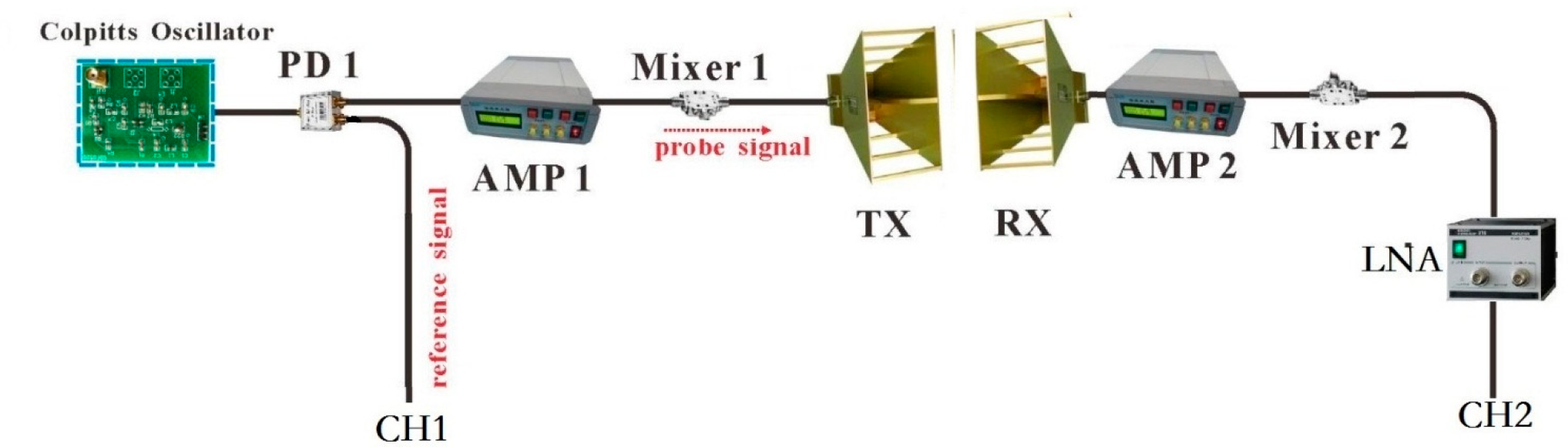
2.1. System Description

A block diagram of the chaotic microwave radar system developed by us is presented in Figure 1. The chaotic signal generated by an improved Colpitts chaotic oscillator passes through a power divider (PD1) where one output serves as a reference signal, and the other amplified (AMP1) output goes to a mixer (Mixer1) and is modulated on a 2 GHz carrier signal. Here, the carrier signal is generated by a signal generator (SG). The up-converted probe signal then is transmitted to the target by a ridge horn transmit antenna (TX) with an operating frequency range from 1 to 18 GHz and a reported gain of about 11 dBi in the 1–3 GHz frequency band. The echo signal is received by the other identical receive antenna (RX) and demodulated to the original chaotic signal by another mixer (Mixer2). A power amplifier (AMP2) and a low noise amplifier (LNA) are used to magnify the echo signal. The delayed probe signal is recorded along with the reference signal by an oscilloscope (OSC) with 3 GHz bandwidth and 10 GS/s sampling rate. The reference signal and the delayed returned signal are cross-correlated and averaged by a computer (PC). The lag values at the corresponding peaks signify the delay between transmitted and reflected signal.
For long-range radar application, the delay due to system components can generally be neglected. However, through wall radar systems are sensitive to such errors due to the smaller distances to targets. We need a calibration procedure to estimate the time delay due to the system components. In calibration setup, as can be seen in Figure 2, two antennas are placed oppositely and closely so that the correlating result represents the distance difference in electro circuit and the correlation peak is set as starting point. After the calibration, the front edge of the antenna can be used as the reference point in space.

2.2. Mathematical Model

Let V C 1 ( t ) represent the chaotic waveform generated by an improved Colpitts oscillator. The chaotic output is fed into the IF port of the Mixer1, and the local-oscillator (LO) port of Mixer1 is driven by a signal generator. The output of signal generator can be represented by the equation
V L O ( t ) = cos ω r e f t
and ω r e f = 2 π f r e f, where f r e f is the frequency output of signal generator.
The mixed output is fed into the transmit antenna and radiates towards the target scene. The transmitted signal from the antenna is
V t ( t ) = K 1 V C 1 ( t ) cos ω r e f t + n 1 ( t )
and K 1 is the constant and n 1 ( t ) is the system noise.
For through wall detection, the wall with thickness d1 is placed between the radar and a target. If interior reflections inside the wall are considered, then the thickness of wall is required. As a practical consideration, the radar is located at a fixed location and the antennas closely stick to the front of the wall. The radar transmits the chaotic waveform and measures the reflected signal. The double-pass propagation factor is expressed as follows:
A ( d ) = exp ( 2 γ 1 d 1 2 γ 2 d 2 ) = exp [ 2 ( α 1 d 1 + α 2 d 2 ) ] exp [ 2 j ( β 1 d 1 + β 2 d 2 ) ]
where γ1 = α1 + 1, γ2 = α2 + 2 are the transmission coefficients associated with the one-way propagation through a dielectric wall and in air, respectively. Here, α1, β1 are attenuation constant and phase constant of the wall, and α2, β2 are attenuation and phase constant related to the air. d2 is the one-way transmission distance of the signal in the air.
The target return at the receive antenna position is given by
V r ( t ) = K 2 Γ exp [ 2 ( α 1 d 1 + α 2 d 2 ) ] V C 1 ( t τ ) cos [ ω r e f ( t τ ) 2 ( β 1 d 1 + β 2 d 2 ) θ ] + n 2 ( t )
where ρ = Γ exp() represents the target reflectivity; K2 is constant; τ represents the two-way propagation delay from the antenna location to the target. n2(t) involves the clutter signals usually due to the coupling between antennas, the background return signals and noise signals.
The demodulated receiving signal by the Mixer2 is expressed as
V d ( t ) = K 3 Γ exp [ 2 ( α 1 d 1 + α 2 d 2 ) ] V C 1 ( t τ ) cos [ ω r e f τ 2 ( β 1 d 1 + β 2 d 2 ) θ ] + n 2 ( t )
The cross-correlation function of V C 1 ( t )and V d ( t )is given by
U ( ς ) = lim T T / 2 T / 2 V d ( t ) V C 1 ( t ς ) d t = lim T T / 2 T / 2 { K 4 V C 1 ( t τ ) cos [ ω r e f τ 2 ( β 1 d 1 + β 2 d 2 ) θ ] + n 2 ( t ) } V C 1 ( t ς ) d t = K 4 cos [ ω r e f τ 2 ( β 1 d 1 + β 2 d 2 ) θ ] lim T T / 2 T / 2 V C 1 ( t τ ) V C 1 ( t ς ) d t + lim T T / 2 T / 2 n 2 ( t ) V C 1 ( t ς ) d t = K 5 lim T T / 2 T / 2 V C 1 ( t τ ) V C 1 ( t ς ) d t + U 1 ( t ) = K 6 g ( τ ς )
where U 1 ( t ) = lim T T / 2 T / 2 n 2 ( t ) V C 1 ( t ς ) d t, when T→∞, U1 (t)→0. T is the correlation time, K4, K5, K6 are constants.

2.3. Chaotic Transmitter

In this radar system, an improved microwave chaotic Colpitts oscillator is employed to generate the source signal. The modeling, design and implementation of the improved chaotic oscillator have been investigated in detail [20]. In this circuit, ultrahigh frequency chaos could be generated by modulating the supply voltages at appropriate values. In experiments, the drive current and voltage of Colpitts chaotic oscillator are 1.8 mA and 13.8 V, respectively. The generated chaotic signal waveform, power spectrum, autocorrelation trace, and attractor are shown in Figure 3a–d, respectively. Obviously, the chaotic waveform varies rapidly and irregularly, which is a noise-like signal. The peak-to-peak value is approximately 600 mV. The power spectrum, shown in Figure 3b, rolls off from its peak value at 0.3 GHz by roughly 20 dB at 5 MHz and 1.7 GHz, which indicate that although Colpitts circuit is a simple structure, it can indeed generate wideband chaotic signal to meet the requirements of UWB radar. The corresponding full width at half maximum (FWHM) of the correlation peak is 0.5 ns (Figure 3c), which depends on the bandwidth of chaotic signal and means the theoretical range resolution of 7.5 cm. The attractor further indicates its randomness, and the delay Δt is 0.1 ns which just is the sampling interval (Figure 3d).

3. Experimental Results

3.1. Target Ranging in Free Space

The ability of range finding in free space is first investigated to demonstrate the performance of our chaotic radar system. In experiment, a metallic plate is used as the detection target and is placed in the front of the antennas without any obstacles between the target and the antennas. Figure 4 shows the experimental results for the cases that the target is located at the different distances. When the target is placed close to the room back wall, not only the target, the back wall response can also be detected. Note that all results in these experiments were obtained with average of 100 times to diminish the unwanted noise fluctuations and improve the signal-to-noise ratio.
As we have known, down range resolution is an important parameter, which describes the radar ability to discriminate two targets that are close toward the signal irradiation (downrange). If two targets are separated in downrange by more than this resolution, the radar can distinguish both targets and can provide both returns. Otherwise, the radar may distinguish only one return, consisting of both targets jammed. Here, experiments for detection of metallic plate through a wooden plate were performed, with the aim to measure the downrange resolution of the chaotic radar system for through wall that was designed. In experiment, a wooden plate and a metallic plate with distances of 2.04 m and 2.51 m away the antenna in the line of sight are measured simultaneously. The reflected signals from the wooden plate and the metallic plate provide the positions of two targets in downrange. Two peaks with different magnitudes can be observed in the result (Figure 5a). The first peak is due to the reflection with the wooden plate, and the second peak is due to the reflection with the metallic plate. The separation between two targets is measured to be 0.47 m, which is in accordance with the experimental arrangement. With the reduction of distance between two plates, as shown in Figure 5b, the separation of two peaks is measured to be 12 cm, which is the minimum distance to be distinguished. Therefore, we achieve experimentally the range resolution of 12 cm for this Colpitts chaotic radar system. This range resolution is more than limit of 7.5 cm due to the noise influence inside the system, the interference during the signal propagating in free space, and so on.

3.2. Wall Construction

To test the radar system performance for through wall scenarios, a 20 cm thick cinder block wall was designed and constructed that was 1.5 m tall by 2.3 m wide. The wall dielectric constant is an important parameter that affects through-wall sensing. Although the cinder block is low loss dielectric material, there may be situations where the transmission loss through wall may be high at specific frequencies of frequency bands. In order to have a compressive understanding to the penetration performance of the designed wall and choose the optimal frequency band, frequency response of the wall is tested experimentally. The test result is shown in Figure 6. The peaks and troughs in the transmission and reflection coefficient can be clearly seen and the weak trend showing higher loss at higher frequencies can also be observed. Transmitting a wideband signal ensures that at least some of the energy can get through the wall and permit the processing of the target-reflected signals. In our system, we use a 2 GHz carrier signal to modulated the chaotic signal and realize the spectrum shifting of the probe signal due to the antennas work band of 1–18 GHz.

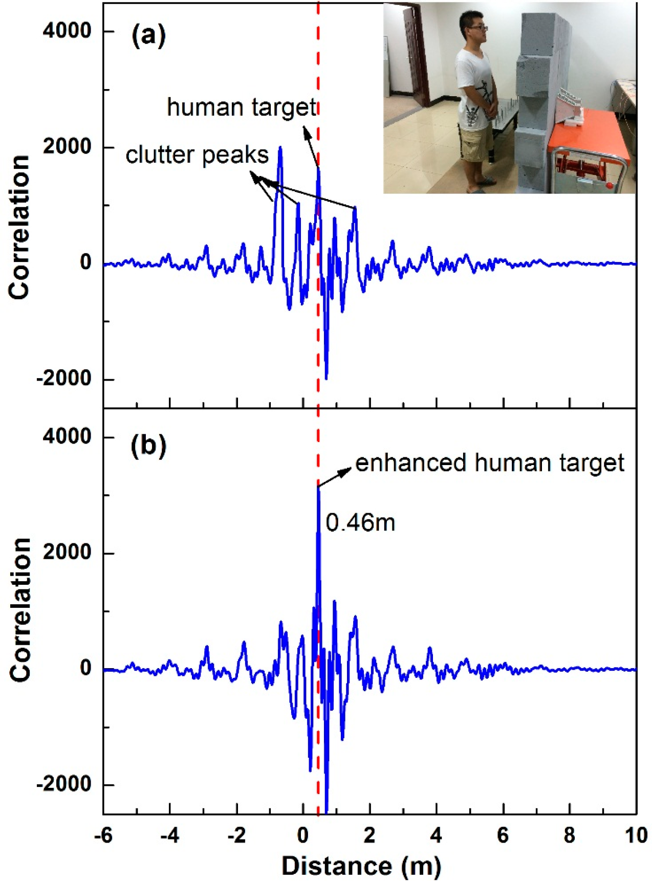
3.3. Through Wall Target Detection

To perform the data collection, the experimental environment consists of the radar system, the wall and the target. In our experiments, we focus to a metallic plate and a human as targets, respectively. A major problem in through-wall radar is the existence of large “clutter peaks” in the reflected response due to the cross-talk between transmit and receive antenna, or to waves scattered from walls, furniture, etc. These signals can obscure the target reflections. In order to overcome this limitation, background subtraction technique [21] is used for the chaotic radar to isolate information about the target and increase the chance of detection. That is, we measure the scene with no target and to generate a range plot of the background firstly. This background plot is then subtracted from the scene with the target to help to enhance the response from the target by reducing the background response.
Firstly the metallic plate was placed at about 1.8 m behind the wall. The transmitting-receiving antennas were mounted in parallel and at the same 1.2 m height on a moved support. The antennas were separated horizontally by 10 cm and closely stick to the front of the wall. The modulated chaotic signal passed through the cinder block wall of 20 cm thickness and reflected from the metallic plate. Figure 7a depicts the original range profile after correlating the replica of the chaotic source signal with the demodulated received signal. Notice that the delay time correction was done and the front edge of the antenna was used as the zero reference point. The inset is the experimental scene. We witness more “clutter” peaks in the correlation profile due to the incomplete isolation between the receptor and transmitter antennas, the reflection from the wall and electromagnetic environment of the experimental conditions. We cannot distinguish the target peak from the clutter peaks clearly. Figure 7b shows the comparison result when the background subtraction technique is used, where the antenna coupling and the background noise have decreased and that there is a single enhanced peak clearly at about 1.99 m from the radar for the target.
Figure 8a,b show the typical output for the human detection. Figure 8a depicts the previous correlation (range) profiles, the plot contains the background response and antenna coupling, the weak reflection from the human is difficult to be identified. The simple background subtraction resulted in the excellent suppression of constant no target induced responses and significant enhancement of the target-induced response, as can be seen from the Figure 8b. In this particular case, the human target was located approximately 0.26 m behind the wall and 0.46 m distance to the radar. Beyond 1.0 m, targets were not easily discernible given the constraints of the wall length and antenna beamwidth.

4. Conclusions

A through-wall UWB microwave chaotic radar system is designed and developed. The microwave chaotic signal is generated by an improved Colpitts oscillator. Target detection and ranging are achieved by cross-correlating a copy of probe signal with the delayed return waveform. Preliminary experimental results show that the designed radar system can be used to locate the target through lossy media. A metallic plate placed 1.79 m and a human stand 0.26 m behind the 20 cm thick cinder block wall are ranged, respectively. In order to detect the weak reflected signal from the target, background subtraction technique is used to increase the chance of detection. Compared with the noise radar system, we notice that the chaotic signal with comparable bandwidth and large amplitude is easily achieved by using a simple nonlinear circuit. It can reduce the unit cost without loss of high performance in through-wall detection and is cost-effective for radar system integration.
The radar systems for through-wall must be immune from jamming and external electromagnetic interference. It has been verified by simulation that two Colpitts oscillators can be synchronized, which is very suitable for the usage of recovering chaotic radar signals from noise and interference. Furthermore, it is important to recognize that the oscillator used here is not the only possible choice. Other chaotic oscillators may have other interesting properties that could be further exploited in radar applications. Exploring such possibilities is the focus of our current and future effort.

Acknowledgments

This work is supported by the Young Scientists Fund of the National Natural Science Foundation of China (Grant No. 61401299), the National Science and Technology Infrastructure Program of the Ministry of Science and Technology of Shanxi Province, China (Grant No. 2013091021), the Natural Science Foundation of Shanxi Province (Grant No.2013011019-3, No. 2012021013-2) and the Graduate Innovation Project in Shanxi Province.
PACS Codes: 05.45 Gg; 84.40 Xb

Author Contributions

Bingjie Wang designed the research and wrote the paper. Hang Xu, Peng Yang and Li Liu performed the experiment and analyzed the data. Jingxia Li designed the chaotic source circuit. All authors have read and approved the final manuscript.

Conflicts of Interest

The authors declare no conflict of interest.

References

  1. Baranoski, E.J. Through-wall imaging: Historical perspective and future directions. J. Frankl. Inst. 2008, 345, 556–569. [Google Scholar]
  2. Narayanan, R.M.; Xu, Y.; Hoffmeyer, P.D.; Curtis, J.O. Design, performance, and applications of a coherent ultra-wideband random noise radar. Opt. Eng. 1998, 37, 1855–1869. [Google Scholar]
  3. Chen, P.C.; Narayanan, R.M.; Lai, C.P.; Davydov, A. Through Wall Ranging and Imaging Using UWB Random Noise Waveform: System Design Considerations and Preliminary Experimental Results, Proceedings of the Antennas and Propagation Society International Symposium 2009, Charleston, SC, USA, 1–5 June 2009; IEEE: New York, NY, USA, 2009; pp. 1–4.
  4. Wang, H.; Narayanan, R.M.; Zhou, Z.O. Through-wall imaging of moving targets using UWB random noise radar. IEEE Antennas Wirel. Propag. Lett. 2009, 8, 802–805. [Google Scholar]
  5. Chen, P.H.; Shastry, M.C.; Lai, C.P.; Narayanan, R.M. A portable real-time digital noise radar system for through-the-wall imaging. IEEE Trans. Geosci. Remote Sens 2012, 50, 4123–4134. [Google Scholar]
  6. Bucolo, M.; Caponetto, R.; Fortuna, L.; Frasca, M.; Rizzo, A. Does chaos work better than noise? IEEE Circuits Syst. Mag. 2002, 2, 4–19. [Google Scholar]
  7. Li, G.H. Chaos and synchronization of Colpitts oscillators. Microw. Opt. Technol. Lett. 2003, 39, 446–449. [Google Scholar]
  8. Qiao, S.; Shi, Z.G.; Jiang, T.; Chen, K.S.; Cui, W.Z.; Ma, W.; Jiang, T.; Ran, L.X. A new architecture of UWB radar utilizing microwave chaotic signals and chaos synchronization. Prog. Electromagn. Res. 2007, 75, 225–237. [Google Scholar]
  9. Sobhy, M.I.; Shehata, A.R. Chaotic radar systems. IEEE MTT-S Int. Microw. Symp. Dig. 2000, 3, 1701–1704. [Google Scholar]
  10. Flores, B.C.; Solis, E.A.; Thomas, G. Assessment of chaos based FM signals for range-Doppler imaging. IEEE Proc. Radar Sonar Navig 2003, 150, 313–322. [Google Scholar]
  11. Hara, Y.; Hara, T.; Seo, T.; Yanagisawa, H.; Ratliff, P.; Machowski, W. Development of a chaotic signal radar system for vehicular collision-avoidance 2002. [CrossRef]
  12. Lin, F.Y.; Liu, J.M. Chaotic Radar Using Nonlinear Laser Dynamics. IEEE J. Quantum Electron 2004, 40, 815–820. [Google Scholar]
  13. Jiang, T.; Long, J.; Wang, Z.; Qiao, S.; Cui, W.; Ma, W.; Huangfu, J.; Ran, L. Experimental investigation of a direct chaotic signal radar with Colpitts oscillator. J. Electromagn. Waves Appl 2010, 24, 1229–1239. [Google Scholar]
  14. Jiang, T.; Qiao, S.; Shi, Z.G.; Peng, L.; Huangfu, J.; Cui, W. Z.; Ma, W.; Ran, L. X. Simulation and experimental evaluation of the radar signal performance of chaotic signals generated from a microwave Colpitts oscillator. Prog. Electromagn. Res. 2009, 90, 15–30. [Google Scholar]
  15. Shi, Z.G.; Qiao, S.; Chen, K.S.; Cui, W. Z.; Ma, W.; Jiang, T.; Ran, L. X. Ambiguity functions of direct chaotic radar employing microwave chaotic Colpitts oscillator. Prog. Electromagn. Res. 2007, 77, 1–14. [Google Scholar]
  16. Blakely, J.N.; Corron, N.J. Concept for low-cost chaos radar using coherent reception. SPIE Def. Secur. Sens. 2011. [Google Scholar] [CrossRef]
  17. Corron, N.J.; Stahl, M.T.; Harrison, R.C.; Blakely, J.N. Acoustic detection and ranging using solvable chaos. Chaos Interdiscip. J. Nonlinear Sci 2013, 23, 213–223. [Google Scholar]
  18. Venkatasubramanian, V.; Leung, H. A novel chaos-based high-resolution imaging technique and its application to through-the-wall imaging. IEEE Signal Process. Lett. 2005, 12, 528–531. [Google Scholar]
  19. Venkatasubramanian, V.; Leung, H.; Liu, X. Chaos UWB radar for through-the-wall imaging. IEEE Trans. Image Process 2009, 18, 1255–1265. [Google Scholar]
  20. Li, J.X.; Wang, Y.C.; Ma, F.C. Experimental demonstration of 1.5 GHz chaos generation using an improved Colpitts oscillator. Nonlinear Dyn 2013, 72, 575–580. [Google Scholar]
  21. Piccardi, M. Background subtraction techniques: A review 2004. [CrossRef]
Figure 1. System block diagram of the chaotic radar system. PD: power divider; AMP: amplifier; SG: signal generator; TX: transmit antenna; RX: receive antenna; LNA: low noise amplifier; OSC: oscilloscope; PC: personal computer.
Entropy 17 02082f1
Figure 2. The diagram of the calibration scenario.
Entropy 17 02082f2
Figure 3. Properties of the used chaotic signal. (a) Temporal waveform. (b) Power spectrum. (c) Autocorrelation trace. (d) Attractor.
Entropy 17 02082f3
Figure 4. Ranging results in free space with the target is located at different distances from the radar system.
Entropy 17 02082f4
Figure 5. (a) Dual-targets ranging result in free space; (b) 12 cm range resolution.
Entropy 17 02082f5
Figure 6. Frequency response of the 20cm thick cinder block wall.
Entropy 17 02082f6
Figure 7. Ranging results with the metallic plate located behind the wall. (a) original range profile; (b) comparison result after background subtraction.
Entropy 17 02082f7
Figure 8. Ranging results with the human stand behind the wall. (a) original range profile; (b) comparison result after background subtraction.
Entropy 17 02082f8

