Effect of Molybdenum Additives on Corrosion Behavior of (CoCrFeNi)100−xMox High-Entropy Alloys


1
School of Mechanical Engineering, University of Science and Technology Beijing, Beijing 100083, China
2
Nuclear Engineering and Radiological Sciences, University of Michigan, Ann Arbor, MI 48109, USA
*
Author to whom correspondence should be addressed.
Entropy 2018, 20(12), 908; https://doi.org/10.3390/e20120908
Submission received: 6 October 2018
/
Revised: 21 November 2018
/
Accepted: 26 November 2018
/
Published: 28 November 2018
(This article belongs to the Special Issue New Advances in High-Entropy Alloys)
Abstract
:The present work investigates the influence of micro-alloyed Mo on the corrosion behavior of (CoCrFeNi)100−xMox high-entropy alloys. All of the (CoCrFeNi)100−xMox alloys exhibit a single face-centered cubic (FCC) solid solution. However, the (CoCrFeNi)97Mo3 alloy exhibits an ordered sigma (σ) phase enriched in Cr and Mo. With the increase of x (the Mo content) from 1 to 3, the hardness of the (CoCrFeNi)100−xMox alloys increases from 124.8 to 133.6 Vickers hardness (HV), and the compressive yield strength increases from 113.6 MPa to 141.1 MPa, without fracture under about a 60% compressive strain. The potentiodynamic polarization curve in a 3.5% NaCl solution indicates that the addition of Mo has a beneficial effect on the corrosion resistance to some certain extent, opposed to the σ phase. Furthermore, the alloys tend to form a passivation film in the 0.5 M H2SO4 solution in order to inhibit the progress of the corrosion reaction as the Mo content increases.
1. Introduction
Traditional alloys only have one major element as a matrix [1]. With the increase of the amount of alloying elements and the concentration of minor elements, the alloy forms a fragile intermetallic phase, which not only increases the difficulty of the microstructure, but also may result in a reduction in the mechanical performance [2,3,4]. To overcome these difficulties, high entropy alloys (HEAs) are invented with extensive research interests; HEAs usually compose of five or more kinds of major elements, with the concentration of each principal element being between 5 and 35 at % [5,6,7]. HEAs tend to generate a face-centered cubic (FCC), body-centered cubic (BCC), or hexagonal closed-packed (HCP) multicomponent solid solution phase [8,9]. Some HEAs have been confirmed to achieve a series of excellent properties, such as high strength, high hardness, and glorious corrosion resistance [10,11,12].
The CoCrFeNi alloy has received extensive attention for its outstanding corrosion resistance, ductility, and structure stability [13,14]. However, because of the poor mechanical strength, the application of the CoCrFeNi alloy in engineering has been limited. It has been shown that an ordered σ strengthening phase can be formed by a certain amount of Mo additives, resulting in precipitation strengthening [15,16,17]. However, the excessive addition of Mo causes a large amount of the coarse σ strengthening phase, which may lead to a rapid increase of the alloy brittleness. Furthermore, because of the low electronic potential of Mo, the excessive content of Mo may reduce the corrosion resistance [18,19,20]. Referring to the chemical composition of austenitic stainless steel, the content of Mo in stainless steel is generally less than 3 wt %. Therefore, we also supply a small amount of Mo in addition to the CoCrFeNi alloy, in order to study the corrosion resistance of the (CoCrFeNi)100−xMox alloy for the development of an HEA system, with a good performance of both strength and corrosion resistance.
In this paper, the as-cast (CoCrFeNi)100−xMox (x =1, 2, and 3 wt %) HEAs have been prepared mainly by vacuum arc melting. The excellent corrosion behavior was investigated by the electrochemical experiments.
2. Materials and Methods
2.1. Samples Fabrication
Elements Co, Cr, Fe, Ni, and Mo with purities of over 99.9 wt % were prepared as raw materials previously. The as-cast (CoCrFeNi)100−xMox (x = 1, 2, and 3, represented by Mo1, Mo2, and Mo3, respectively) were prepared by vacuum arc melting and were fabricated under the WK-∏ vacuum arc melting furnace at least five times in the crucible, so as to ensure the chemical homogeneity. The size of the ingot was approximately Φ 35 × 10 mm, and the ingot was annealed for 3 h under 500 °C and was cooled in the air so as to release the residual stress caused by rapid cooling during casting.
2.2. Microstructure of the (CoCrFeNi)100−xMox Alloys
The crystalline phases of the (CoCrFeNi)100−xMox alloys were identified by X-ray diffraction (XRD), using an Ultima IV X-ray diffractometer with Cu Kα radiation. The X-ray diffractometer has an operating voltage of 30 kV and an operating current of 20 mA with the diffraction angle (2θ) from 20 to 90°, at a scanning rate of 4°/min.
Etching the (CoCrFeNi)100−xMox alloys with aqua regia (HNO3: HCl = 1:3, volume fraction) and using FE-SEM JEOL JEM-7600F scanning-electron microscopy (SEM) (JEOL Ltd., Tokyo, Japan) equipped with an energy dispersive spectrometer (EDS) allowed for an analysis of the microstructure and composition.
2.3. Mechanical Properties
The microhardness was measured using a Wolpert-401MVD Vickers hardness tester (WOLPERT Co., Norwood, MA, USA) with loads of 500 g and a duration of 10 s. The measurements were performed at 10 different locations on each sample, and the average value of the 10 measurements was calculated. Compressive tests were carried out on the Φ 3 × 6 mm samples, using the universal testing machine (CMT 4305) (MTS Co., Eden Prairie, MN, USA) with a strain rate of 10−3 s−1.
2.4. Electrochemical Corrosion Test
The electrochemical experiments were performed on (CoCrFeNi)100−xMox alloys, using the Potentiostat Workstation Versa STAT MC (PARSTAT 4000, AMETEK Co., Princeton, NJ, USA). A three-electrode electrochemical cell using a saturated calomel electrode (SCE) as a reference electrode, a platinum plate as an auxiliary electrode, and a sample as a working electrode were tested. The electrochemical experiments of the (CoCrFeNi)100−xMox alloys were conducted in a 3.5% NaCl and 0.5 M H2SO4 solution at room temperature, respectively. The potentiodynamic polarization measurements were taken at a scan rate of 1 mV/s from a potential scanning range of −0.5 V to 1.1 V.
2.5. Corroded Microstructure
The electrochemically tested alloys were cleaned using an ultrasonic cleaner, and then dried in nitrogen. SEM and EDS were used to study the morphology of the corrosion surface of the high-entropy alloys.
3. Results and Discussion
3.1. Microstructure of the (CoCrFeNi)100−xMox Alloys
Figure 1 represents the XRD pattern of the (CoCrFeNi)100−xMox (x = 1, 2, 3) alloys. All of the samples of alloys have a single FCC solid solution structure, which was confirmed by the predecessors [21]. As the Mo content increases, the peak intensity changes, but the FCC phase is kept. As the Mo content becomes 3 wt % (Mo3 structure), the small peak on the left of the matrix FCC phase in the XRD patterns is identified as Cr and Mo rich σ phase, which agrees with the previous remarks [22].
The SEM images of the (CoCrFeNi)100−xMox (x = 1, 2, and 3) alloys presented in Figure 2 shows that the alloys are composed of typical dendritic structures. Region A is interdendrites and region B is dendrites. Figure 2c presents the SEM image of the Mo3 alloy, and region D is the grain boundary. Figure 2d is a part of the SEM of the Mo3 alloy. The EDS results of the (CoCrFeNi)100−xMox alloys are shown in Table 1. According to the EDS, the dendrite is the Co and Fe rich phase, and the interdendrite is the Cr and Mo rich phase. Combined with the XRD and EDS results, the Mo3 alloy exhibits Cr and Mo rich σ phase in the interdendrite. When the content of Mo is 1 and 2 wt %, there is no formation of a precipitate phase in the alloy because of the high entropy effect. However, HEAs undergo spinodal decomposition inside the crystal grains during cooling, leading to the formation of microstructures with the same structure but different compositions.
3.2. Mechanical Properties
Figure 3 shows the Vickers hardness (HV) of the (CoCrFeNi)100−xMox alloys as a function of the Mo content. The alloy hardness increases from 124.83 to 133.60 HV, with the Mo content increasing from 1 to 3 wt %. When the content of the Mo element is 3 wt %, the presence of the σ phase results in a remarkable increase in the hardness.
Besides the hardness, we have examined the stress–strain relationships. The compressive stress–strain curves and the inner longitudinal-section SEM images of the (CoCrFeNi)100−xMox (x = 1, 2, and 3) alloys are shown in Figure 4. After yielding, the strength of the alloys increases continuously. All of the three samples do not break under about a 60% compressive strain, indicating that the alloys possess a good ductility, flexibility, and fracture strain. As shown in Figure 4b–d, the deformation of the Mo3 subgrain boundaries is more prominent in the angle of 45°, probably due to the resolved shear stress.
3.3. Environmental Effect on Corrosion Behavior
3.3.1. Corrosion Behavior in Chloride-Containing Solutions
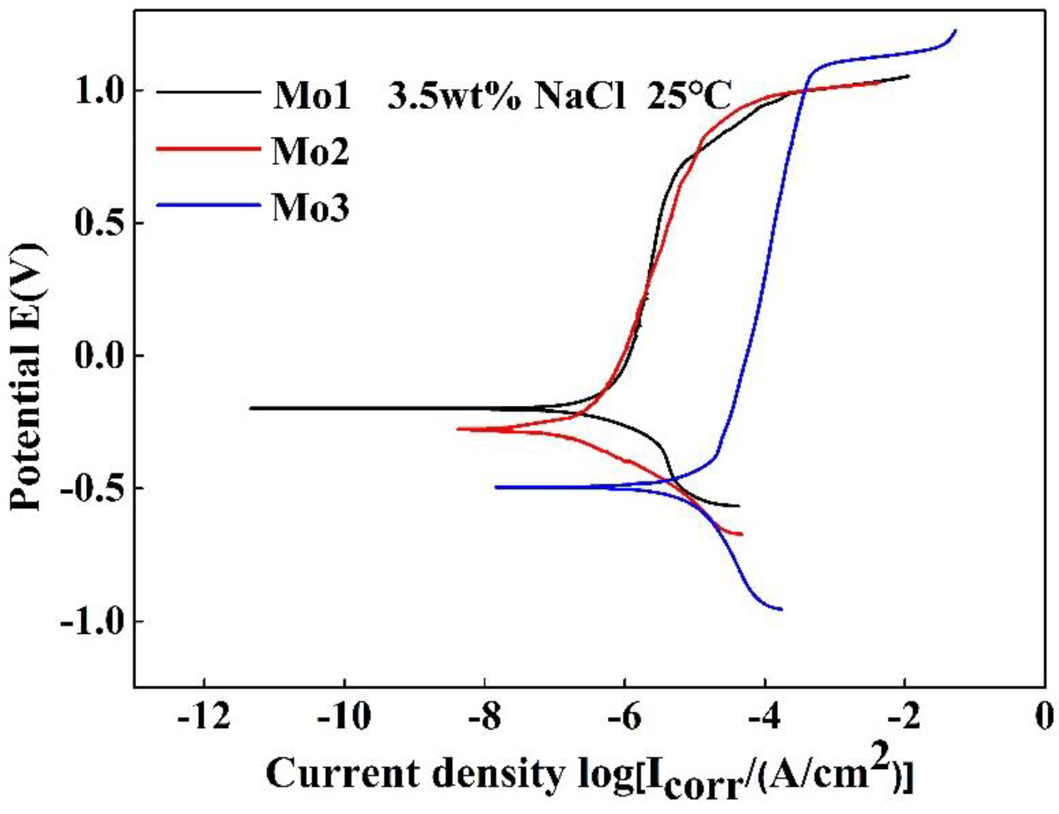
Figure 5 lists the polarization curve of the (CoCrFeNi)100−xMox (x = 1, 2, and 3) alloys in a 3.5% NaCl solution. The corrosion potential of the alloys gradually shifts to more positive potentials with a decreasing Mo content.
Table 3 presents the electrochemical parameters of the (CoCrFeNi)100−xMox (x = 1, 2, and 3) alloys in a 3.5% NaCl solution. The corrosion current densities (icorr) of the Mo1, Mo2, and Mo3 alloys were 0.4, 0.24, and 6.6 μA/cm2, and the corrosion potentials (Ecorr) were −199, −277, and −493 mV, respectively. The breakdown potential (Eb) gradually shifts to more positive potentials. Epit is a primary passivation potential. ∆E is the passive region width, defined as the difference between the Eb and Epit. The icorr value of the Mo3 alloy is an order of magnitude higher than the other two. The corrosion resistance of Mo3 was dropped. Therefore, the presence of the Cr and Mo rich σ phase in the Mo3 alloy leads to the diminution of the corrosion resistance.
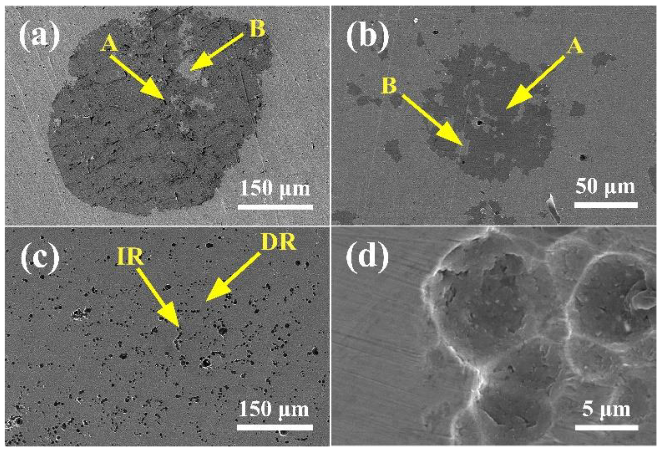
Figure 6 presents the microstructure of the (CoCrFeNi)100−xMox alloys after potentiodynamic polarization in a 3.5% NaCl solution. DR is dendrite and IR is interdendrite. According to the SEM images, the majority of types of corrosion were mainly the pitting corrosion. The Mo3 alloy is more susceptible to pitting corrosion, which is consistent with the polarization curve results. Region A is a Cr-rich phase and region B is a Mo-rich phase. There is an element of segregation that causes the corrosion to occur. The interdendritic phase of Mo3 is the Cr- and Mo-rich phase, and the dendrite is a Cr- and Mo-depleted phase. Therefore, galvanic corrosion occurred at the junctions of dendrites. The XRD and SEM result show that the Mo and Cr rich σ phase appeared inside the interdendrite, the corrosion occurred at the interfaces around σ phase, as shown in Figure 6c,d. The results of the EDS of the alloy after corrosion are summarized in Table 4.
3.3.2. Corrosion Behavior in Acid Solutions
Figure 7 shows the polarization curve of the (CoCrFeNi)100−xMox (x = 1, 2, and 3) alloys in 0.5 M H2SO4. Table 5 presents the electrochemical parameters of the (CoCrFeNi)100−xMox (x = 1, 2, and 3) alloys in 0.5 M H2SO4. The ipp is the lunt current density. It can be seen from the electrochemical parameters that the icorr was 34.1, 28.0, and 15.4 μA/cm2, respectively. The Ecorr shifted to more positive potentials, and the icorr value dropped as the Mo content increased. This suggests that the alloys tend to form a passivation film to inhibit the progress of the corrosion reaction.
Figure 8 shows the SEM microstructure of the (CoCrFeNi)100−xMox alloys after potentiodynamic polarization in a 0.5 M H2SO4 solution, combined with EDS, because the low potential of Mo is enriched and the Cr2O3 is insufficient in region A. Consequently, region A is more susceptible to corrosion in the H2SO4 solution. When the content of Mo is 3 wt %, as Figure 8c indicates, the results of the EDS analysis show that the concentration of element Cr in region A is reduced, and the content of Mo in region B is significantly higher than that in region A, the effect of Mo was to form Mo (VI) oxyhydroxide or molybdate (MoO42−), decreasing the rate of dissolution in active zones. Hence, the corrosion of the Mo3 alloy is concentrated in region A.
Figure 9a shows the comparison of the corrosion behavior between the HEAs and the conventional corrosion resistant alloys in a 3.5% NaCl solution, compared with those of the conventional corrosion resistant alloys [25,26]. The HEAs are located in the upper part of Figure 9a, the Ecorr of the HEAs are more positive than those of the Mn alloys, Ni alloys, and some of the Ti alloys. On the other hand, the icorr of the HEAs are much lower than some of Mn alloys and are comparable with the Ti alloys, which indicates that the corrosion resistance of the HEAs is comparable or even better than those of the conventional alloys. However, the partial icorr of the HEAs is higher than that of the total, because the presence of the σ phase is catastrophic for HEAs. Figure 9b presents the comparison of the corrosion behavior between the HEAs and the conventional corrosion resistant alloys in the 0.5 M H2SO4 solution. Compared with the conventional alloys [27,28], the Ecorr of the HEAs are much more positive than those of the Ti alloys and Ni alloys. The icorr of the HEAs are much lower than the Ti alloys, Ni alloys, and some of the Cu alloys. As a general trend, the corrosion resistance of the HEAs in the 0.5 M H2SO4 solution is better than those of the conventional alloys.
4. Conclusions
The (CoCrFeNi)100−xMox (x = 1, 2, and 3) alloys have been synthesized. Their microstructures, mechanical properties, and corrosion behaviors have been experimentally investigated. The microstructures of the (CoCrFeNi)100−xMox (x = 1, 2, and 3) alloys belong to a single FCC structure. The increase in Mo promotes the formation of the Cr- and Mo-rich σ phase. The hardness and compressive yield strength increase obviously with an increase of the Mo content from 1 to 3 wt %. Regarding the potentiodynamic polarization curves of the (CoCrFeNi)100−xMox alloys in a 3.5% NaCl solution, the curves of the Mo1 and Mo2 alloys indicated that the increase of the Mo content increases the corrosion resistance of the chloride environment to some extent. However, the Cr and Mo rich σ phase is present at the grain boundary of the Mo3 alloy, resulting in a decreasing in corrosion resistance in the 3.5% NaCl solution. Furthermore, the potentiodynamic polarization curves of the (CoCrFeNi)100−xMox alloys in the 0.5 M H2SO4 solution yielded an extensive passive region, and as the content of the Mo increased, the corrosion current density gradually decreased. Therefore, in an acidic solution, the addition of Mo has a positive effect on the corrosion resistance of the (CoCrFeNi)100−xMox alloys.
Author Contributions
Conceptualization, W.W.; formal analysis, J.W.; methodology, J.W. and W.Q.; resources, W.W.; writing (original draft), J.W.; writing (review and editing), J.W., H.Y. and Q.P.
Funding
The authors are grateful for the financial support provided by the Fundamental Research Funds for the Central Universities (FRF-TP-16-044A1 and FRF-GF-17-B18) and the National Natural Science Foundation of China (21703007).
Acknowledgments
The authors would like to thank the project team assistance with funding. Many thanks to the tutor for his thoughtful and thorough guidance.
Conflicts of Interest
The authors declare no conflict of interest.
References
- Peng, Q.; Meng, F.; Yang, Y.; Lu, C.; Deng, H.; Wang, L.; De, S.; Gao, F. Shockwave generates <100> dislocation loops in bcc iron. Nat. Commun. 2018, 9, 4880. [Google Scholar] [CrossRef] [PubMed]
- Ye, Q.; Feng, K.; Li, Z.; Lu, F.; Li, R.; Huang, J.; Wu, Y. Microstructure and corrosion properties of CrMnFeCoNi high entropy alloy coating. Appl. Surface Sci. 2017, 396, 1420–1426. [Google Scholar] [CrossRef]
- Shun, T.T.; Chang, L.Y.; Shiu, M.H. Age-hardening of the CoCrFeNiMo0.85 high-entropy alloy. Mater. Charact. 2013, 81, 92–96. [Google Scholar] [CrossRef]
- Senkov, O.N.; Zhang, F.; Miller, J.D. Phase composition of a CrMo0.5NbTa0.5TiZr high entropy alloy: Comparison of experimental and simulated data. Entropy 2013, 15, 3796–3809. [Google Scholar] [CrossRef]
- Qiu, X.W.; Zhang, Y.P.; He, L.; Liu, C.-G. Microstructure and corrosion resistance of AlCrFeCuCo high entropy alloy. J. Alloys Compd. 2013, 549, 195–199. [Google Scholar] [CrossRef]
- Zhang, Y.; Tang, T.T.Z.Z.; Gao, M.C.; Dahmen, K.A.; Liaw, P.K.; Lu, Z.P. Microstructures and properties of high-entropy alloys. Prog. Mater. Sci. 2014, 61, 1–93. [Google Scholar] [CrossRef]
- Tung, C.C.; Yeh, J.W.; Shun, T.-T.; Chen, S.K.; Huang, Y.S.; Chen, H.C. On the elemental effect of AlCoCrCuFeNi high-entropy alloy system. Mater. Lett. 2007, 61, 1–5. [Google Scholar] [CrossRef]
- Yeh, J.W. Recent progress in high entropy alloys. Ann. Chim. Sci. Mat. 2006, 31, 633–648. [Google Scholar] [CrossRef]
- Zhang, H.; Pan, Y.; He, Y.Z. Synthesis and characterization of FeCoNiCrCu high-entropy alloy coating by laser cladding. Mater. Des. 2011, 32, 1910–1915. [Google Scholar] [CrossRef]
- Chen, Y.; Duval, T.; Hung, U.; Yeh, J.; Shih, H. Microstructure and electrochemical properties of high entropy alloys—A comparison with type-304 stainless steel. Corros. Sci. 2005, 47, 2257–2279. [Google Scholar] [CrossRef]
- Qiu, X.-W.; Wu, M.J.; Liu, C.G.; Zhang, Y.P.; Huang, C.-X. Corrosion performance of Al2CrFeCoxCuNiTi high-entropy alloy coatings in acid liquids. J. Alloys Compd. 2017, 708, 353–357. [Google Scholar] [CrossRef]
- Zhang, Y.; Yan, X.H.; Liao, W.B.; Zhao, K. Effects of nitrogen content on the structure and mechanical properties of (Al0.5CrFeNiTi0.25) Nx high-entropy films by reactive sputtering. Entropy 2018, 20, 624. [Google Scholar] [CrossRef]
- Hsu, Y.J.; Chiang, W.C.; Wu, J.K. Corrosion behavior of FeCoNiCrCux high-entropy alloys in 3.5% sodium chloride solution. Mater. Chem. Phys. 2005, 92, 112–117. [Google Scholar] [CrossRef]
- Shi, Y.; Yang, B.; Liaw, P.K. Corrosion-resistant high-entropy alloys: A review. Metals 2017, 7, 43. [Google Scholar] [CrossRef]
- Zhu, J.; Zhang, H.; Fu, H.; Wang, A.; Li, H.; Hu, Z. Microstructures and compressive properties of multicomponent AlCoCrCuFeNiMox alloys. J. Alloys Compd. 2010, 497, 52–56. [Google Scholar] [CrossRef]
- Zhu, J.; Fu, H.; Zhang, H.; Wang, A.; Li, H.; Hu, Z. Microstructures and compressive properties of multicomponent AlCoCrFeNiMox alloys. Mater. Sci. Eng. A 2010, 527, 6975–6979. [Google Scholar] [CrossRef]
- Miao, J.; Guo, T.; Ren, J.; Zhang, A.; Su, B.; Meng, J. Optimization of mechanical and tribological properties of FCC CrCoNi multi-principal element alloy with Mo addition. Vacuum 2018, 149, 324–330. [Google Scholar] [CrossRef]
- Nilsson, J.O.; Kangas, P.; Wilson, A.; Karlsson, T. Mechanical properties, microstructural stability and kinetics of σ-phase formation in 29Cr-6Ni-2Mo-0.38 N superduplex stainless steel. Metall. Mater. Trans. A 2000, 31, 35–45. [Google Scholar] [CrossRef]
- Lopez, N.; Cid, M.; Puiggali, M. Influence of o-phase on mechanical properties and corrosion resistance of duplex stainless steels. Corros. Sci. 1999, 41, 1615–1631. [Google Scholar] [CrossRef]
- Schwind, M.; Källqvist, J.; Nilsson, J.O.; Ågren, J.; Andrén, H.O. σ-phase precipitation in stabilized austenitic stainless steels. Acta Mater. 2000, 48, 2473–2481. [Google Scholar] [CrossRef]
- Tsau, C.H.; Tsai, M.C. The effects of Mo and Nb on the microstructures and properties of CrFeCoNi (Nb, Mo) alloys. Entropy 2018, 20, 648. [Google Scholar] [CrossRef]
- Chou, Y.; Yeh, J.; Shih, H. The effect of molybdenum on the corrosion behaviour of the high-entropy alloys Co1.5CrFeNi1.5Ti0.5Mox in aqueous environments. Corros. Sci. 2010, 52, 2571–2581. [Google Scholar] [CrossRef]
- Zhang, L.; Yu, P.; Zhang, M.; Liu, D.; Zhou, Z.; Ma, M.; Liaw, P.; Li, G.; Liu, R. Microstructure and mechanical behaviors of GdxCoCrCuFeNi high-entropy alloys. Mater. Sci. Eng. A 2017, 707, 708–716. [Google Scholar] [CrossRef]
- Li, T.; Liu, B.; Liu, Y.; Guo, W.; Fu, A.; Li, L.; Yan, N.; Fang, Q. Microstructure and mechanical properties of particulate reinforced NbMoCrTiAl High Entropy based composite. Entropy 2018, 20, 517. [Google Scholar] [CrossRef]
- Wu, C.; Zhang, S.; Zhang, C.; Zhang, H.; Dong, S. Phase evolution and cavitation erosion-corrosion behavior of FeCoCrAlNiTix high entropy alloy coatings on 304 stainless steel by laser surface alloying. J. Alloys Compd. 2017, 698, 761–770. [Google Scholar] [CrossRef]
- Qiu, X.W.; Liu, C.G. Microstructure and properties of Al2CrFeCoCuTiNix high-entropy alloys prepared by laser cladding. J. Alloys Compd. 2013, 553, 216–220. [Google Scholar] [CrossRef]
- Lee, C.; Chang, C.; Chen, Y.; Yeh, J.; Shih, H. Effect of the aluminium content of AlxCrFe1.5MnNi0.5 high-entropy alloys on the corrosion behaviour in aqueous environments. Corros. Sci. 2008, 50, 2053–2060. [Google Scholar] [CrossRef]
- Xiao, D.; Zhou, P.; Wu, W.; Diao, H.; Gao, M.; Song, M.; Liaw, P. Microstructure, mechanical and corrosion behaviors of AlCoCuFeNi-(Cr, Ti) high entropy alloys. Mater. Des. 2017, 116, 438–447. [Google Scholar] [CrossRef]
Figure 1.
XRD (X-ray diffraction) patterns of the (CoCrFeNi)100−xMox (x = 1, 2, 3) high entropy alloys.
Figure 1.
XRD (X-ray diffraction) patterns of the (CoCrFeNi)100−xMox (x = 1, 2, 3) high entropy alloys.

Figure 2.
SEM (scanning-electron microscopy) images of the (CoCrFeNi)100−xMox high-entropy alloys: (a) x = 1; (b) x = 2; (c) x = 3; (d) 10 × magnification.
Figure 2.
SEM (scanning-electron microscopy) images of the (CoCrFeNi)100−xMox high-entropy alloys: (a) x = 1; (b) x = 2; (c) x = 3; (d) 10 × magnification.

Figure 3.
Vickers hardness of the (CoCrFeNi)100−xMox high-entropy alloys as a function of the Mo content.
Figure 3.
Vickers hardness of the (CoCrFeNi)100−xMox high-entropy alloys as a function of the Mo content.

Figure 4.
(a) Compressive stress–strain curves and the inner longitudinal-section SEM images of the (CoCrFeNi)100−xMox alloys after compression deformation: (b) x = 1; (c) x = 2; (d) x = 3.
Figure 4.
(a) Compressive stress–strain curves and the inner longitudinal-section SEM images of the (CoCrFeNi)100−xMox alloys after compression deformation: (b) x = 1; (c) x = 2; (d) x = 3.

Figure 5.
Polarization curves of the (CoCrFeNi)100−xMox (x = 1, 2, and 3) alloys in a 3.5% NaCl solution.
Figure 5.
Polarization curves of the (CoCrFeNi)100−xMox (x = 1, 2, and 3) alloys in a 3.5% NaCl solution.

Figure 6.
SEM images of (CoCrFeNi)100−xMox after potentiodynamic polarization in a 3.5% NaCl solution: (a) x = 1; (b) x = 2; (c) x = 3; (d) the interdendrite morphology of the Mo3 alloy.
Figure 6.
SEM images of (CoCrFeNi)100−xMox after potentiodynamic polarization in a 3.5% NaCl solution: (a) x = 1; (b) x = 2; (c) x = 3; (d) the interdendrite morphology of the Mo3 alloy.

Figure 7.
Polarization curves of the (CoCrFeNi)100−xMox (x = 1, 2, and 3) alloys in a 0.5 M H2SO4 solution
Figure 7.
Polarization curves of the (CoCrFeNi)100−xMox (x = 1, 2, and 3) alloys in a 0.5 M H2SO4 solution

Figure 8.
SEM images of (CoCrFeNi)100−xMox after potentiodynamic polarization in a 0.5 M H2SO4 solution: (a) x = 1; (b) x = 2; (c) x = 3; (d) partial view of the Mo3 alloy.
Figure 8.
SEM images of (CoCrFeNi)100−xMox after potentiodynamic polarization in a 0.5 M H2SO4 solution: (a) x = 1; (b) x = 2; (c) x = 3; (d) partial view of the Mo3 alloy.

Figure 9.
Comparison of the icorr and Ecorr between high entropy alloys (HEAs) and conventional alloys: (a) in a 0.5 M NaCl solution; (b) in a 0.5 M H2SO4 solution.
Figure 9.
Comparison of the icorr and Ecorr between high entropy alloys (HEAs) and conventional alloys: (a) in a 0.5 M NaCl solution; (b) in a 0.5 M H2SO4 solution.


Table 1.
Element concentration determined using the energy dispersive spectrometer (EDS) of the three samples of the (CoCrFeNi)100−xMox alloys (at %).
Table 1.
Element concentration determined using the energy dispersive spectrometer (EDS) of the three samples of the (CoCrFeNi)100−xMox alloys (at %).
| Element | Cr | Fe | Co | Ni | Mo | |
|---|---|---|---|---|---|---|
| Mo1 | Dendrite | 25.25 | 23.54 | 26.07 | 24.53 | 0.61 |
| interdendrite | 27.69 | 22.31 | 24.03 | 24.94 | 1.04 | |
| Mo2 | Dendrite | 26.02 | 25.17 | 24.55 | 23.56 | 0.69 |
| interdendrite | 27.20 | 23.20 | 23.33 | 23.87 | 2.40 | |
| Mo3 | Dendrite | 24.99 | 23.47 | 25.28 | 24.96 | 1.31 |
| interdendrite | 26.82 | 22.54 | 24.81 | 24.35 | 1.50 |
Table 2.
Mechanical properties (yield stress, compressive strength, and fracture strain) of the (CoCrFeNi)100−xMox alloys for x = 1, 2, and 3 as Mo1, Mo2, and Mo3, respectively.
Table 2.
Mechanical properties (yield stress, compressive strength, and fracture strain) of the (CoCrFeNi)100−xMox alloys for x = 1, 2, and 3 as Mo1, Mo2, and Mo3, respectively.
| Alloy | Yield Stress σy (MPa) | Compressive Strength σmax (MPa) | Fracture Strain εp (%) |
|---|---|---|---|
| Mo1 | 113.6 | Not fractured | >60 |
| Mo2 | 119.7 | Not fractured | >60 |
| Mo3 | 141.1 | Not fractured | >60 |
Table 3.
Electrochemical parameters of the (CoCrFeNi)100−xMox alloys in a 3.5% NaCl solution.
| Alloy | Ecorr (mV) | Icorr (μA/cm2) | Eb (mV) | Epit (mV) | ∆E (mV) |
|---|---|---|---|---|---|
| Mo1 | −199 | 0.402 | 992 | −5 | 997 |
| Mo2 | −277 | 0.235 | 968 | −108 | 1076 |
| Mo3 | −493 | 6.610 | 1053 | −358 | 1411 |
Table 4.
EDS results for the Mo3 alloy after the potentiodynamic polarization in a 3.5% NaCl solution.
Table 4.
EDS results for the Mo3 alloy after the potentiodynamic polarization in a 3.5% NaCl solution.
| Element | Region | Cr (%) | Fe (%) | Co (%) | Ni (%) | Mo (%) |
|---|---|---|---|---|---|---|
| Mo1 | A | 26.17 | 24.56 | 23.32 | 25.01 | 0.93 |
| B | 30.79 | 23.79 | 22.87 | 22.51 | 0.04 | |
| Mo2 | A | 26.44 | 23.72 | 24.32 | 23.83 | 1.70 |
| B | 35.81 | 23.79 | 19.78 | 20.11 | 0.52 | |
| Mo3 | DR | 24.96 | 25.21 | 24.72 | 24.88 | 0.23 |
| IR | 29.06 | 23.21 | 22.43 | 22.76 | 2.54 |
Table 5.
Electrochemical parameters of the (CoCrFeNi)100−xMox alloys in a 0.5 M H2SO4 solution.
| Alloy | Ecorr (mV) | Icorr (μA/cm2) | Epp (mV) | ipp (μA/cm2) | ∆E (mV) |
|---|---|---|---|---|---|
| Mo1 | −294 | 34.1 | −225 | 117 | 655 |
| Mo1 | −290 | 28.0 | −225 | 68 | 681 |
| Mo1 | −279 | 15.4 | −239 | 25 | 751 |
© 2018 by the authors. Licensee MDPI, Basel, Switzerland. This article is an open access article distributed under the terms and conditions of the Creative Commons Attribution (CC BY) license (http://creativecommons.org/licenses/by/4.0/).
Share and Cite
MDPI and ACS Style
Wang, W.; Wang, J.; Yi, H.; Qi, W.; Peng, Q. Effect of Molybdenum Additives on Corrosion Behavior of (CoCrFeNi)100−xMox High-Entropy Alloys. Entropy 2018, 20, 908. https://doi.org/10.3390/e20120908
AMA Style
Wang W, Wang J, Yi H, Qi W, Peng Q. Effect of Molybdenum Additives on Corrosion Behavior of (CoCrFeNi)100−xMox High-Entropy Alloys. Entropy. 2018; 20(12):908. https://doi.org/10.3390/e20120908
Chicago/Turabian StyleWang, Wenrui, Jieqian Wang, Honggang Yi, Wu Qi, and Qing Peng. 2018. "Effect of Molybdenum Additives on Corrosion Behavior of (CoCrFeNi)100−xMox High-Entropy Alloys" Entropy 20, no. 12: 908. https://doi.org/10.3390/e20120908
Note that from the first issue of 2016, this journal uses article numbers instead of page numbers. See further details here.