Thermo-Fluid Characteristics of High Temperature Molten Salt Flowing in Single-Leaf Type Hollow Paddles

1
School of Energy and Power Engineering, Nanjing university of Science and Technology, Nanjing 210094, China
2
Shenzhen Douwin Technology Co., Ltd., Shenzhen 518116, China
3
Key Laboratory of Tropical Forest Ecology, Xishuangbanna Tropical Botanical Garden, Chinese Academy of Sciences, Mengla 666303, China
*
Author to whom correspondence should be addressed.
Entropy 2018, 20(8), 581; https://doi.org/10.3390/e20080581
Submission received: 8 July 2018
/
Revised: 2 August 2018
/
Accepted: 5 August 2018
/
Published: 7 August 2018
(This article belongs to the Special Issue Entropy Generation and Heat Transfer)
Abstract
:A single-leaf type paddle heat exchanger with molten salt as the working fluid is a proper option in high temperature heating processes of materials. In this paper, based on computational fluid dynamics (CFD) simulations, we present the thermo-fluid characteristics of high temperature molten salt flowing in single-leaf type hollow paddles in the view of both the first law and the second law of thermodynamics. The results show that the heat transfer rate of the hollow paddles is significantly greater than that of solid paddles. The penalty of the heat transfer enhancement is additional pressure drop and larger total irreversibility (i.e., total entropy generation rate). Increasing the volume of the fluid space helps to enhance the heat transfer, but there exists an upper limit. Hollow paddles are more favorable in heat transfer enhancement for designs with a larger height of the paddles, flow rate of molten salt and material-side heat transfer coefficient. The diameter of the flow holes influences the pressure drop strongly, but their position is not important for heat transfer in the studied range. Other measures of modifying the fluid flow and heat transfer like internal baffles, more flow holes or multiple channels for small fluid volume are further discussed. For few baffles, their effects are limited. More flow holes reduce the pressure drop obviously. For the hollow paddles with small fluid volume, it is possible to increase the heat transfer rate with more fluid channels. The trade-off among fluid flow, heat transfer and mechanical strength is necessary. The thermo-fluid characteristics revealed in this paper will provide guidance for practical designs.
1. Introduction
Paddle heat exchangers were first used in drying materials, called paddle dryers [1,2,3,4,5,6,7,8]. In high temperature heating industries (e.g., in the range of 300 to 600 °C), molten salts (e.g., Hitec salt) are commonly used as working fluids for heat transfer. Recently, many researchers have investigated molten salt thermo-fluid characteristics in different geometrical structures. For example, Wu et al. [9] experimentally investigated the turbulent flow and transitional flow of molten Hitec salt in a circular tube. Their results provided different convective heat transfer coefficients of molten Hitec salt. Ferng et al. [10] used the computational fluid dynamics (CFD) technique and the two-equation k-ε turbulent model to study the thermal-hydraulic characteristics of molten FLiNaK salt in a circular tube. Their numerical simulation results agree with experimental data and general correlations. Also based on CFD simulation, Srivastava et al. [11] investigated the flow and heat transfer characteristics of molten FLiNaK salt in a circular tube for different flow regimes, i.e., laminar, transitional and turbulent flow. Their numerical predictions agreed with that of the available correlations.
Zhang et al. [12] tested the thermal performance of molten salt cavity receivers. They showed that the flow rate does not have a strong effect on the instantaneous efficiency of the receiver in the pro-steady state. Du et al. [13] experimentally studied the heat transfer performance of molten Hitec salt in the shell side of a shell-and-tube heat exchanger with segmental baffles. New Nusselt number correlation in specified turbulent regime was provided. Later, Du et al. [14] further investigated the heat transfer characteristics of molten Hitec salt in the shell side of a shell-and-tube heat exchanger without baffles experimentally and numerically. The two-equation k-ε turbulent model and Fluent commercial software were used to simulate the convection process. The experimental and numerical results showed good agreement. Lu et al. [15] measured the heat transfer performance of ternary nitrate salt flowing in an annular duct with a cooled wall. Based on experimental data, a new heat transfer correlation in the turbulent regime was proposed. Chen et al. [16], in laminar-transition-turbulent regimes, experimentally investigated the convective heat transfer performance of transversely-grooved tubes with heat transfer salt KNO3-NaNO2-NaNO3 (53-40-7 mol %) as the working fluid. Compared to circular tubes, transversely-grooved tubes show significant heat transfer enhancement.
Except circular tubes and shell-and-tube heat exchangers, the CFD technique has been used in simulating molten salt flow and heat transfer in other geometrical structures. It has been accepted as an important tool in analysis and design. Based on the Reynolds-averaged Navier–Stokes method, Carasik et al. [17] calculated the turbulent pressure drop of molten salt (FLiBe) flow in an in-line heat exchanger. Several one- and two-equation turbulence models were compared. The standard low Reynolds number k-ε turbulent model, which provides reasonable predictions, was recommended. Chen et al. [18] simulated the mixed convection heat transfer of Hitec salt in horizontal square tubes. The two-equation RNG k-ε model was adopted. The comparison of experimental and simulation results showed good agreement. In [19], Hitec salt flow and heat transfer in hollow disc-shaped heaters were simulated by using the standard k-ε model. The optimal design was suggested based on the simulation results. A brief review of high temperature molten salt heat transfer and heat exchangers was given by Du et al. in [20].
Few studies focused on the fluid flow and heat transfer of molten salt in hollow paddle-shaft structures of paddle heat exchangers. Inspired by constructal law [21], Zhang et al. [22] presented the molten salt fluid flow and heat transfer performance of three two-leaf-type paddle-shaft structures and showed that, in the heat transfer aspect, the open hollow paddle-shaft structure is much better than that of closed hollow paddle-shaft structure and solid paddle-shaft structure. Ji et al. [23] further studied the effects of a guiding plate near the outlet flow hole of a two-leaf-type paddle heat exchanger. Their results show that in the two leaves, the fluid flow and heat transfer are non-symmetrical, and it is possible to enhance the heat transfer and decrease the pressure drop simultaneously. In [24], it was shown that the influence of rotation rate (<10 rpm) on fluid flow and heat transfer is negligible. Compared to those two-leaf-type paddle heat exchangers, the single-leaf type design has a higher heat transfer area and a simpler structure and manufacture. This may be used in non-agglutination or weak-agglutination materials [25]. When the heat transfer coefficients of the two sides (i.e., the working fluid side and the material side) are at the same scale, it is helpful to enhance the heat transfer of the working fluid side. Furthermore, the heat transfer enhancement will also improve the temperature uniformity of the heating surfaces, which is important for heating temperature-sensitive materials. Up to now, to the authors’ knowledge, there are no published data on the thermo-fluid characteristics of high temperature molten salt flowing in single-leaf type hollow paddles.
In this paper, we first describe the geometry of single-leaf type hollow paddles, and then build a CFD model to simulate the fluid flow and heat transfer performance for the structures. Based on the simulation results, we identify the optimal design for heat transfer enhancement. The trade-off in designs is also discussed. This work is the starting point prior to real product design, manufacture and testing.
2. Geometry Description
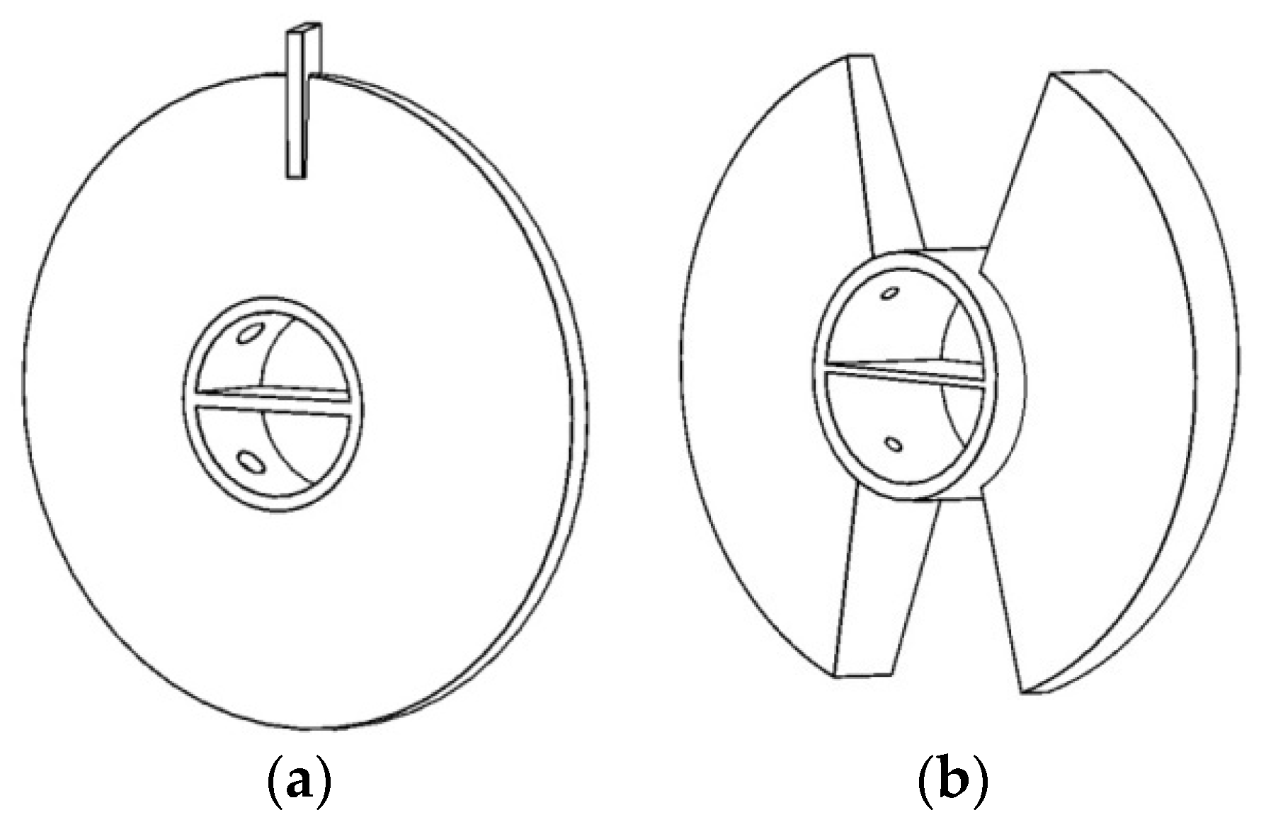
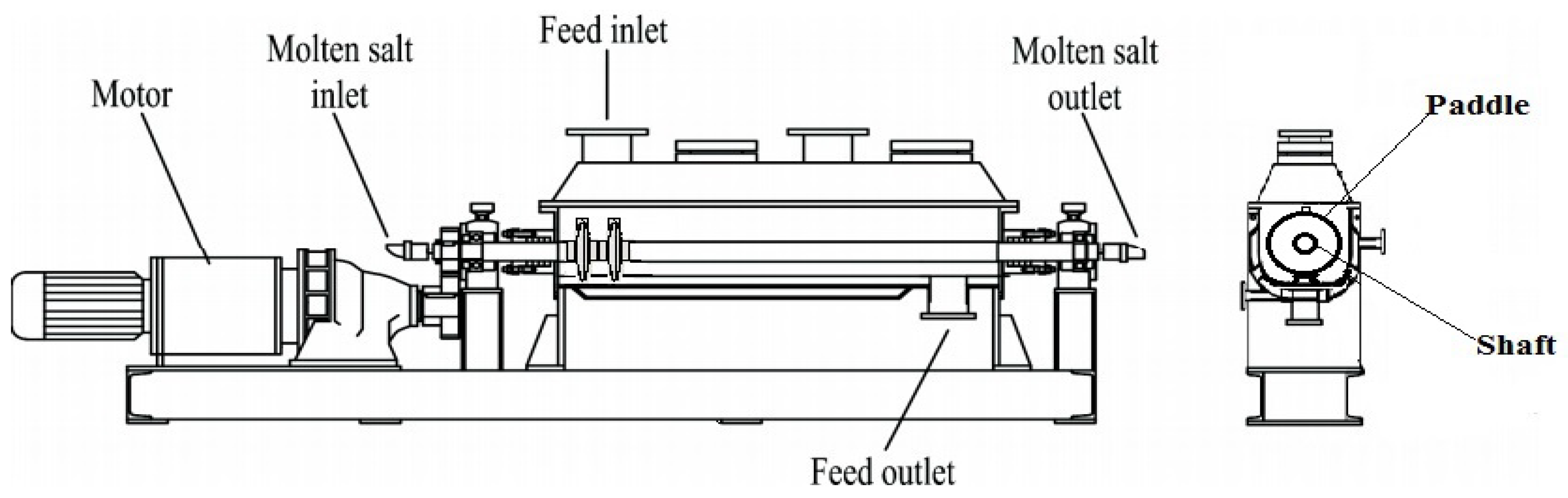
There are two common types of paddles for paddle heat exchangers, i.e., single-leaf type represented in Figure 1a and two-leaf type in Figure 1b. In this study, we only discuss the single-leaf type hollow paddles. Figure 2 shows the cross-section of a heat exchanger with single-leaf type paddles. Under normal working conditions, the working fluid flows in the hollow paddle-shaft structure and heats the shell-side material, which is driven by the rotating paddles. In order to provide sufficient residence time for materials to be heated, the rotation is usually very slow, e.g., less than 10 rpm [24]. The work in [24] has shown that the effect of slow rotation (<10 rpm) is very weak. Therefore, in this paper, we neglect the influence of rotation on flow and heat transfer.
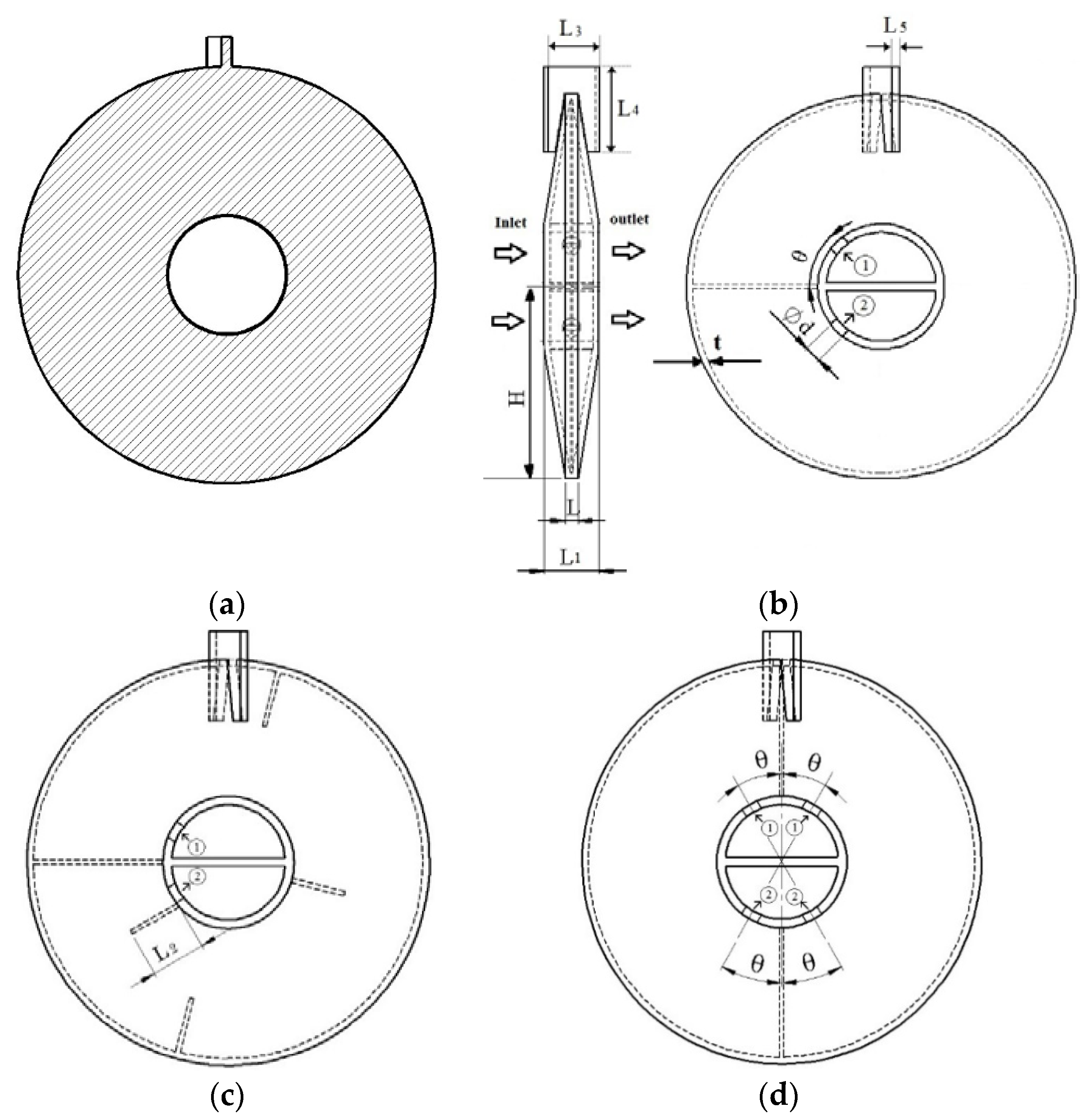
Consider a single-leaf type paddle heat exchanger with Hitec salt (53% KNO3, 40% NaNO2, 7% NaNO3 based on mass fraction) as the working fluid. The overall shaft is composed of some segments. In every segment, there is one paddle for single-leaf type design. We assume that the molten salt is distributed uniformly into all the segments [23], so only one segment is studied. For all shaft-paddle structures to be investigated, the inner and outer diameters of the hollow shaft are the same, so for simplicity, we only discuss the thermo-fluid characteristics in the paddle domain. In order to study the effects of the fluid volume in the hollow paddles, we use the solid paddle design (i.e., zero fluid volume) as the reference. Figure 3 shows the candidate designs: solid paddle and different hollow paddles.
3. Numerical Model
In this section, we present a CFD model to simulate the molten salt flow and heat transfer in the paddle domain shown in Figure 3. The basic assumptions for the simulations are: zero rotation rate, steady turbulent forced flow for molten salt, constant temperature and convective heat transfer coefficient of the shell-side material, constant properties of molten salt and the solid and zero radiation of the outer surfaces of the paddle due to the material’s covering.
The three-dimensional mass, momentum and energy equations for molten salt flow without phase change are presented as follows [26]:
For the solid region, the energy equation is:
The turbulent kinetic energy and its rate of dissipation ε are obtained from the transport Equations (6) and (7), and the turbulent viscosity µt is calculated by combining k and ε according to Equation (8):
In Equation (3), Prt = 0.85 and in Equations (6) and (7), the constants adopt the following values: C1ε = 1.44, C2ε = 1.92, Cµ = 0.09, σk = 1, σε = 1.3 [26]. The boundary conditions and the properties of the materials are given in Table 1 and Table 2, respectively. In Figure 3, the following sizes are assumed constant: L3 = 28 mm, L4 = 41 mm, L5 = 4 mm.
To obtain the flow and temperature fields and the overall thermo-fluid performance (e.g., the pressure drop ΔP of the molten salt flow and the heat transfer rate of the paddle ), we used a finite-volume computational package ANSYS Fluent (14.5, ANSYS, Canonsburg, PA, USA) [28], with the pressure-based solver and SIMPLE algorithm for pressure–velocity coupling, and the second order upwind scheme for momentum and energy equations. The residuals for mass, momentum, turbulent kinetic energy and dissipation rate equations are 10−4, and for the energy equation, the residuals are 10−6. The mesh independence for each simulation was checked. A maximum of 1% changes in pressure drop and heat transfer rate between successive mesh sizes are considered acceptable results. The number of grids varies from case to case, from a few million to more than 10 million. An example of the mesh independence check is given in Table 3. In Table 3, for 7,539,242 and 6,825,664 elements, the differences of the pressure drop (30,997 Pa and 30,992 Pa) and heat transfer rate (2836 W and 2841 W) are both less than 1%. In this case, 7,539,242 elements were selected in the simulations to ensure the mesh independence of the results.
According to the second law of thermodynamics, the irreversible processes take place due to two factors, to be specific, fluid flow and heat transfer. The total irreversibility can be measured by the entropy generation rate. Based on the first and second laws of thermodynamics, we obtain the energy balance and entropy balance equations for the heat transfer process as follows [29,30]:
The entropy generation rate is derived as:
In Equation (11b), the ΔP term corresponds to the fluid flow irreversibility (ΔP-induced entropy generation rate). On the right side of Equation (11b), the sum of the terms except the ΔP term is the heat transfer-induced entropy generation rate.
Based on the CFD model (i.e., Equations (1)–(8)), the pressure drop and heat transfer rate are first obtained. Then, the entropy generation rate is calculated through Equation (11a) or Equation (11b). To compare the performance of hollow paddles and solid paddles, the simulation results are summarized in dimensionless groups as follows:
In Equation (14), if R > 1, the heat transfer performance of the hollow paddle is better than that of the solid paddle. In Equation (15), if S > 1, the total irreversibility in the heat transfer process of the hollow paddle is larger than that of the solid paddle. Because we use Case I as the reference design to define dimensionless groups and the focus is to reveal the advantages or disadvantages of hollow paddles compared to solid paddles, in Section 4, we will not list Case I as an independent subsection. For Case I and ho = 250 W/(m2K), when H = 46, 92 and 184 mm, = 760, 929 and 1021 W, respectively. For Case I and H = 92 mm, when ho = 50 and 150 W/(m2K), = 429 and 758 W, respectively. Therefore, based on the dimensional values for Case I and the dimensionless values documented in Section 4, dimensional results for hollow paddles can be easily obtained.
4. Results and Discussion
4.1. Case II
In product designs, the outer shape of the hollow paddle is determined by the shell-side material, and there exists a least thickness of the paddle wall (t = 3 mm in this paper) regarding the requirement of the mechanical strength. Compared to pure conduction in the solid paddle, both conduction and convection in the hollow paddle affect the heat transfer process. The fluid volume in the hollow paddle is a critical design parameter. The fluid volume ratio is defined as:
where φ = 0 corresponds to the solid paddles. Table 4 shows the simulated cases with different φ.
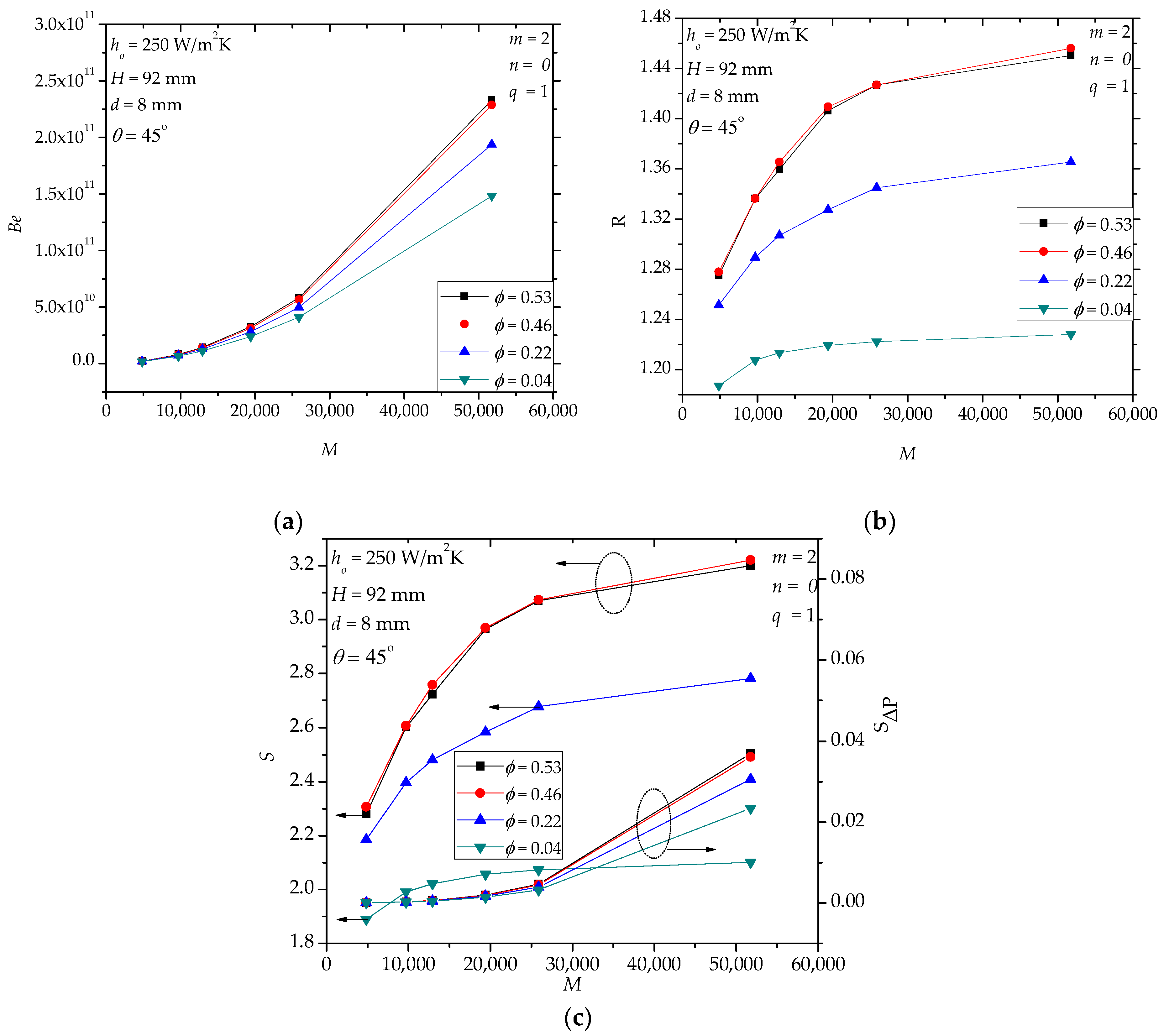
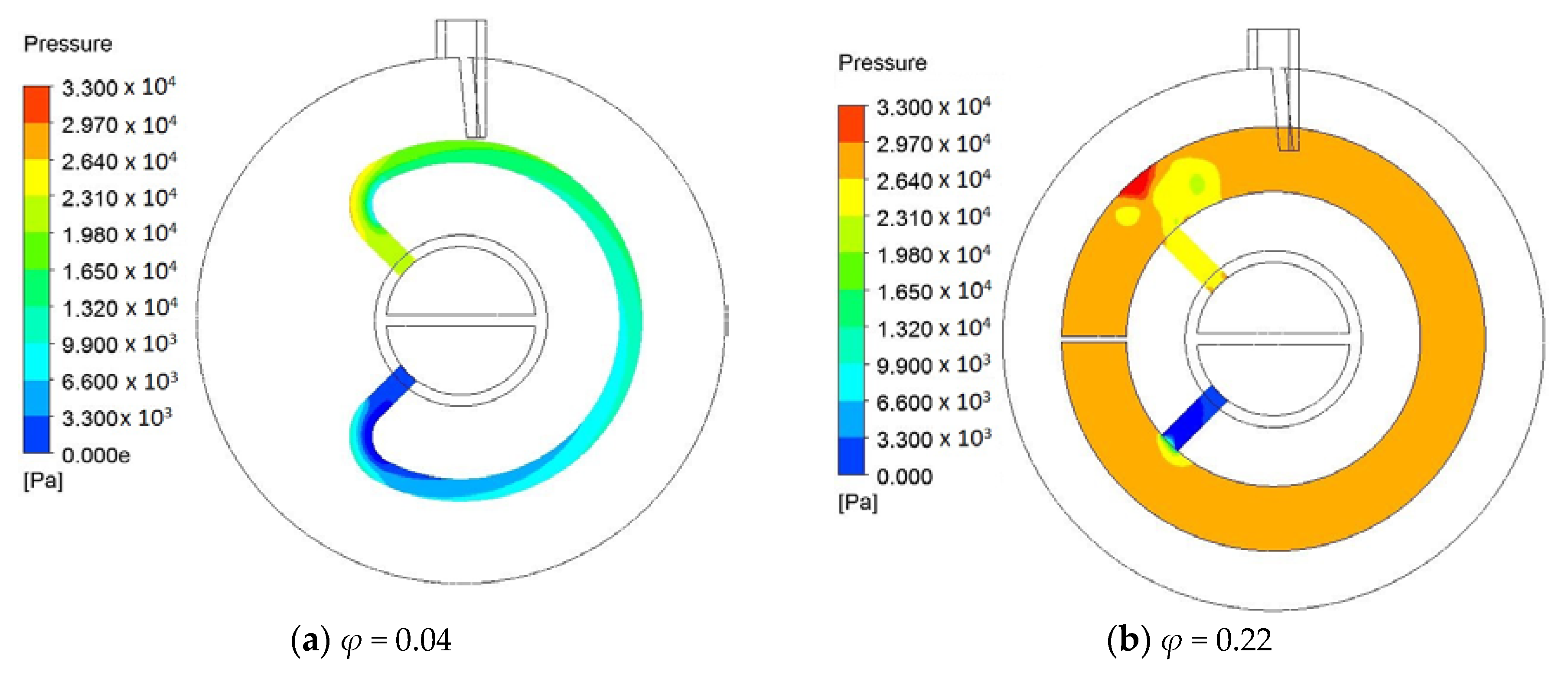
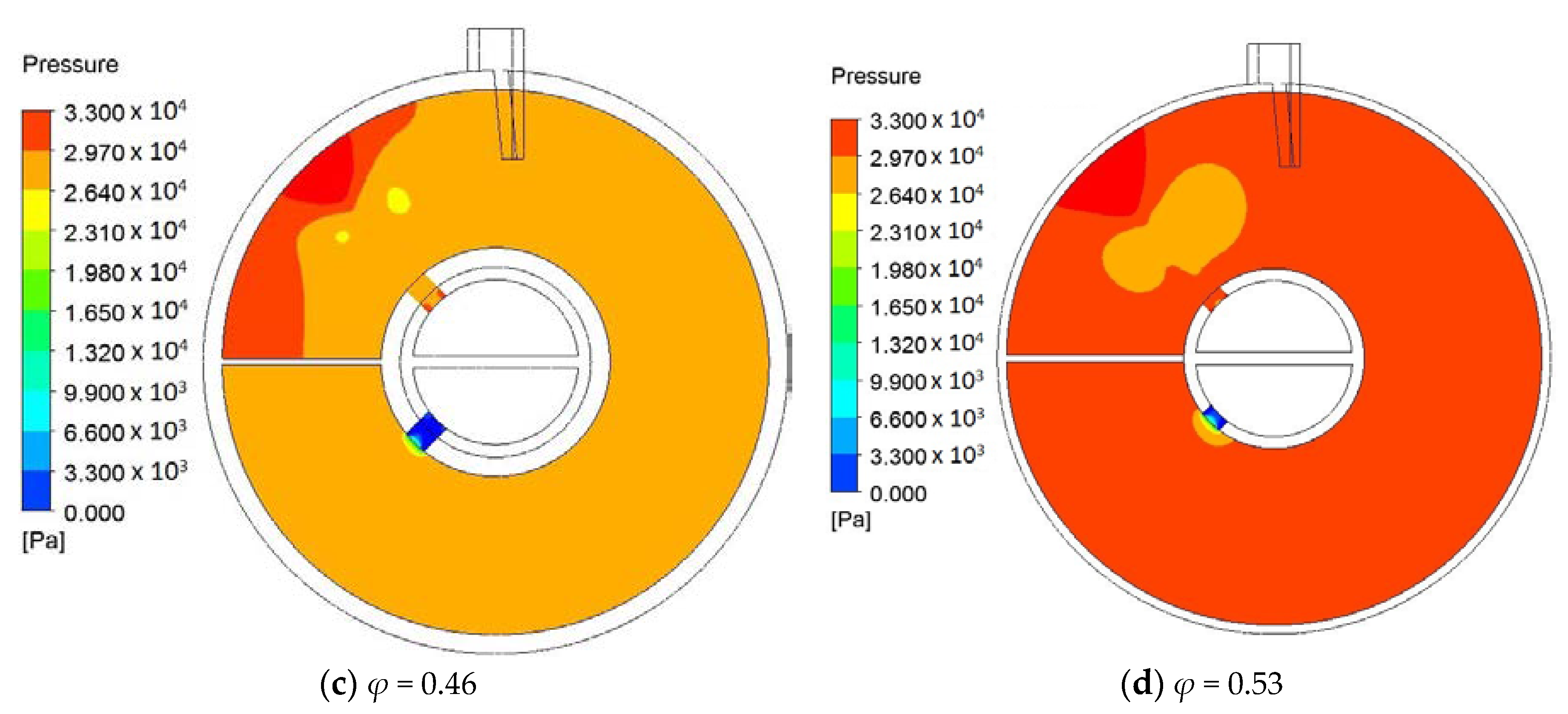
Figure 4 shows the effects of φ of hollow paddles. In Figure 4a, in the range M < 20,000, the effect of φ on Be is small. When M > 20,000, the difference of Be emerges for the designs with different φ. For specified M, Be increases with the increase in φ, especially when φ is small, e.g., φ = 0~0.46. For φ = 0.46 and 0.53, Be is nearly the same. Figure 5 shows an example of the pressure distribution in the middle cross-section of the fluid space. For the hollow paddle with φ = 0.04, the fluid space has a uniform cross-section area (i.e., constant diameter 8 mm), and for such flow in a tube, the pressure drop is mainly caused by the wall friction. Therefore, in this case, the distributed loss (depending on the diameter and the length of the tube for fixed mass flow rate and fluid properties) is dominant. However, for the hollow paddles with a large fluid space (e.g., φ = 0.22, 0.46 and 0.53), in sequence, the molten salt flows through the inlet flow hole with a small diameter, the internal space with both radial flow and circumferential flow and the outlet flow hole. This forms a complicated three-dimensional flow. Both the local losses (e.g., vortex, sudden-convergence and sudden-divergence) and the distributed losses are important. For some examples, like the case in Figure 5d, the pressure changes significantly near the outlet flow hole (sudden-divergence), which can be directly viewed from the color change. However, in other domains, the pressure does not change significantly. This observation tells us that the local loss near the outlet flow hole (sudden-divergence) is dominant.
In Figure 4b, all R values are greater than one, illustrating that the heat transfer performance of the hollow paddles is always better than the corresponding solid paddles in the specified range. In the range φ = 0~0.46, larger φ generates greater heat transfer rate because of stronger convection. This is the mechanism of the heat transfer enhancement of hollow paddles: the introduction of the convection reduces the thermal resistance of the conduction in the paddle. Figure 4b also shows that for φ = 0.46 and 0.53, there is no difference in R. This implies that the heat transfer improvement via increasing φ has an upper limit. In fact, larger φ leads to lower (average) fluid velocity in the fluid space, weakening the advantage of convection. This also means that a trade-off between conduction and convection exists. It is known that for a solid paddle, heat is transferred from its bottom surface (i.e., the hot surface) to its top surface and side surfaces through conduction. The thermal resistance of conduction is proportional to the heat transfer path length. When the hollow structure is introduced in the paddle, convection makes the temperature distribution in the hollow paddle more uniformly than pure conduction in the solid paddle. The effect of convection depends on the velocity. The larger the velocity, the less the thermal resistance. As the fluid volume increases, the velocity drops. If the velocity is too small, convection in the hollow paddle will not work. In Figure 4c, the total entropy generation rate (S) shows a similar trend as the heat transfer rate, which indicates that a greater heat transfer rate leads to larger irreversibility; the price for the heat transfer enhancement. The ΔP-induced entropy generation rate (SΔP) increases with the increase of M, and it is much less than S, which means that the heat transfer contributes to the main irreversibility.
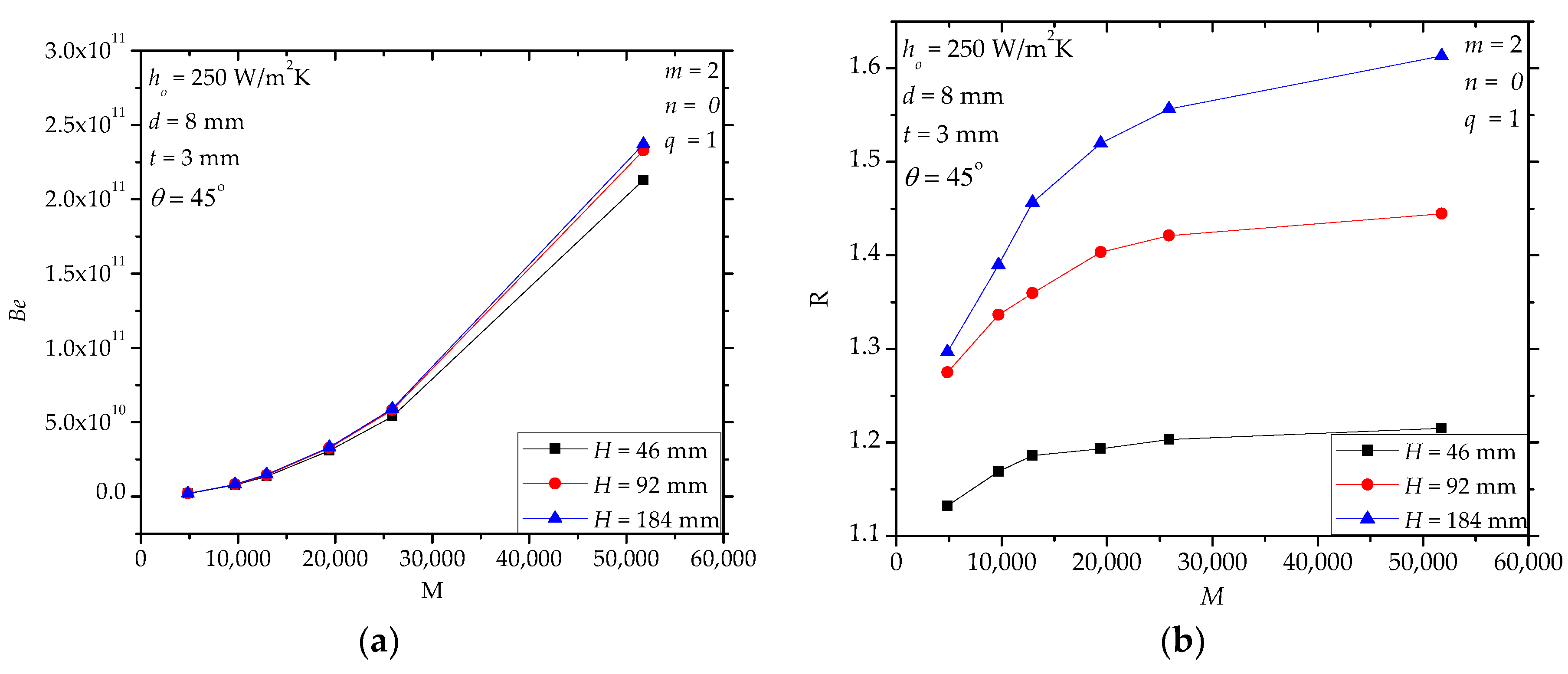
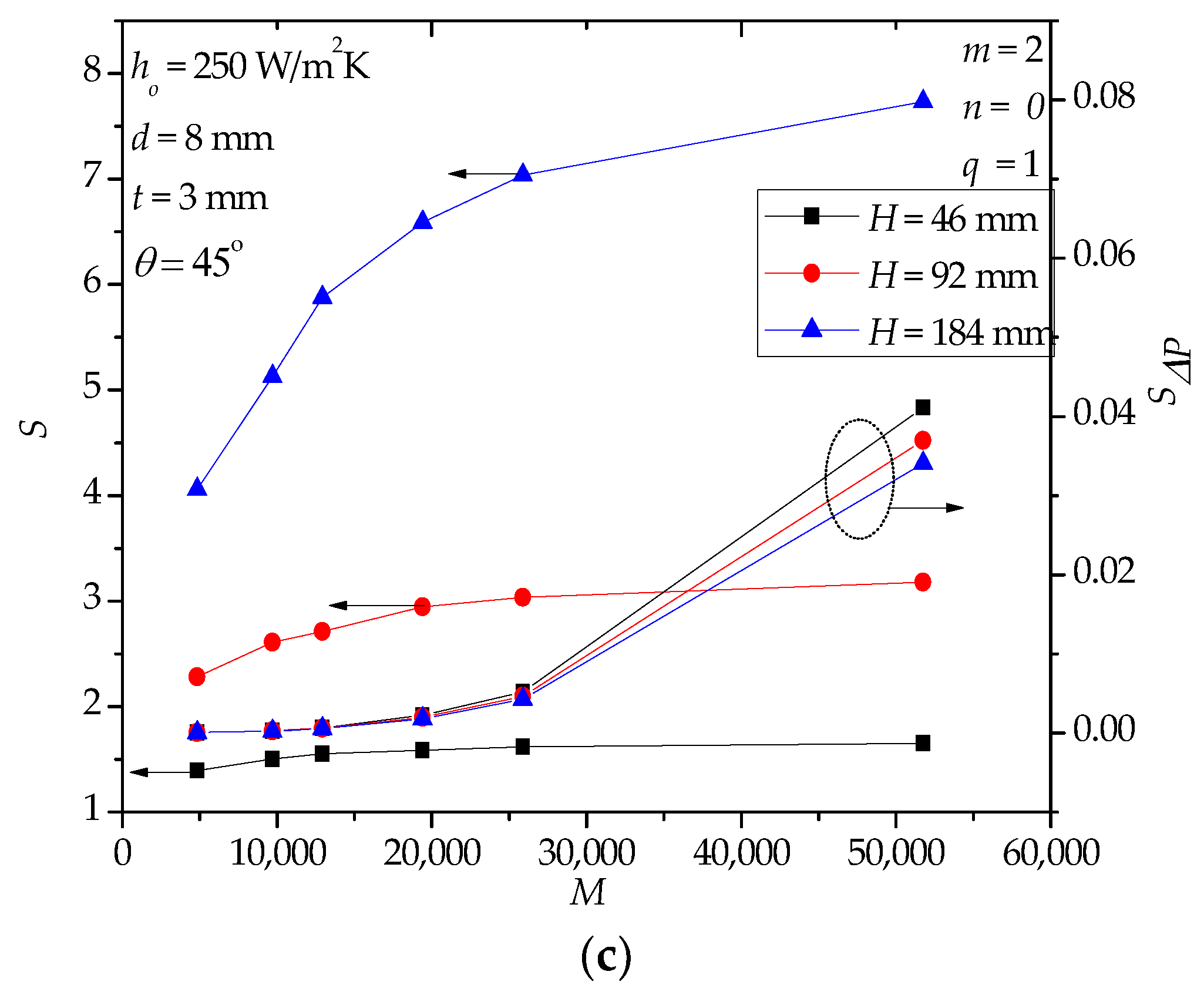
For paddle heat exchangers, the paddle height H determines the heat transfer area and the material driving characteristics. Figure 6a shows that when M is small, e.g., less than 20,000, the effect of H on Be is negligible. When M becomes larger, Be of the design with H = 46 mm is less than that with H = 92 and 184 mm. Figure 6b shows that in the specified range, compared to the solid paddles, the improvement of the heat transfer performance of the hollow paddles is greater when H increases. This is understandable because larger H is equivalent to a longer path or larger thermal resistance of conduction. In this condition, hollow paddles are more favorable. Figure 6c further shows that S increases with the increase of H and the heat transfer-induced irreversibility is dominant.
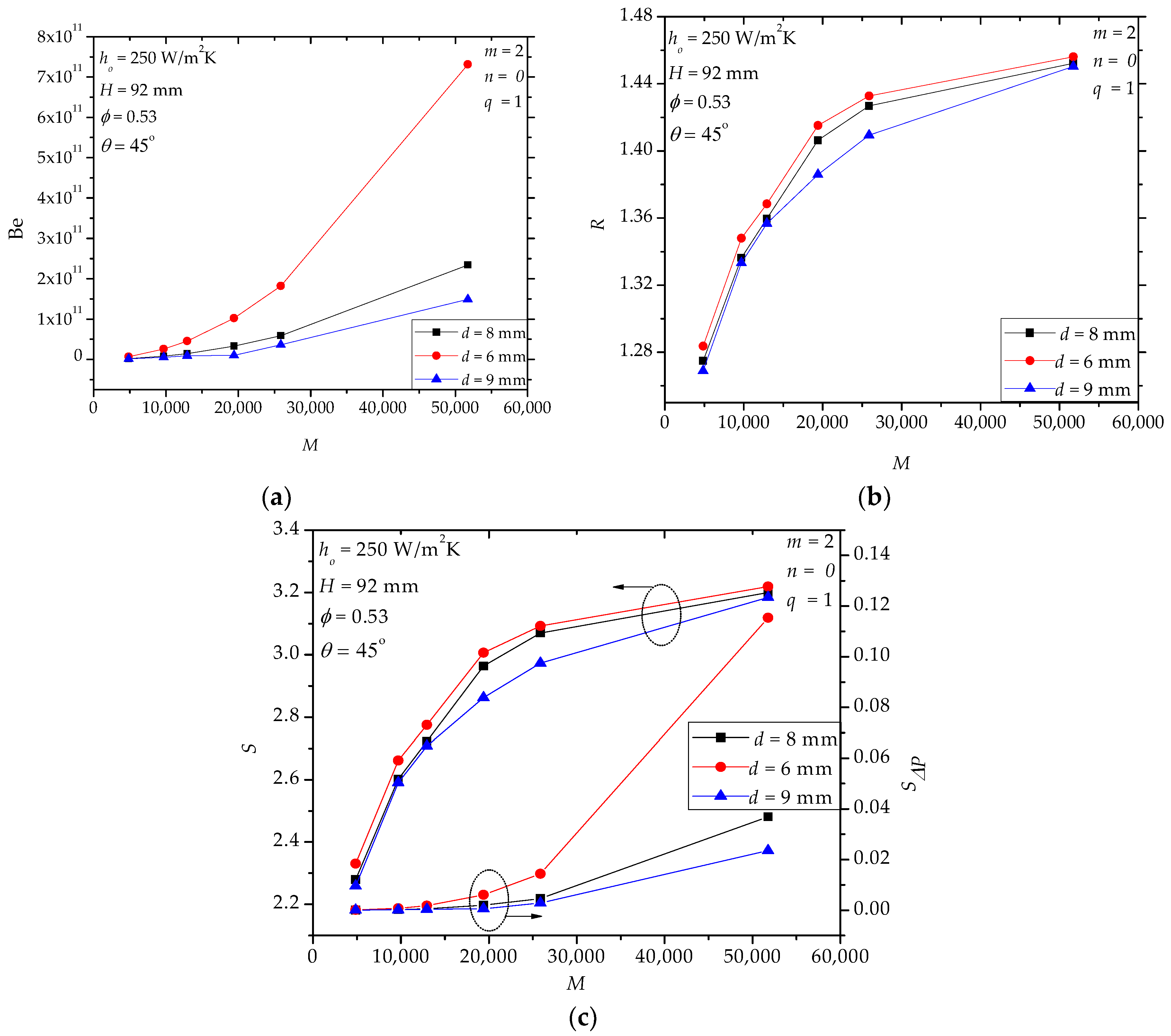
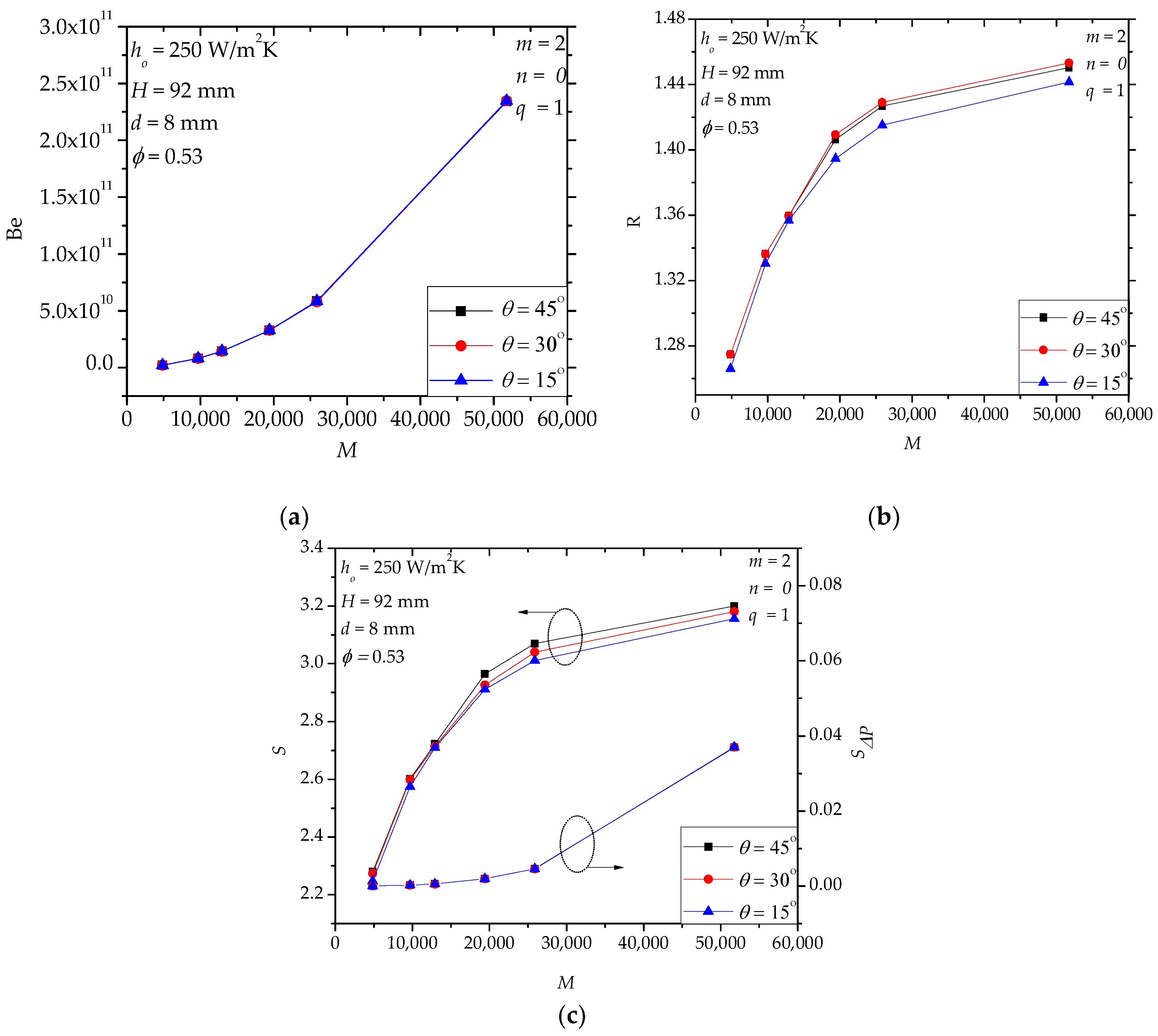
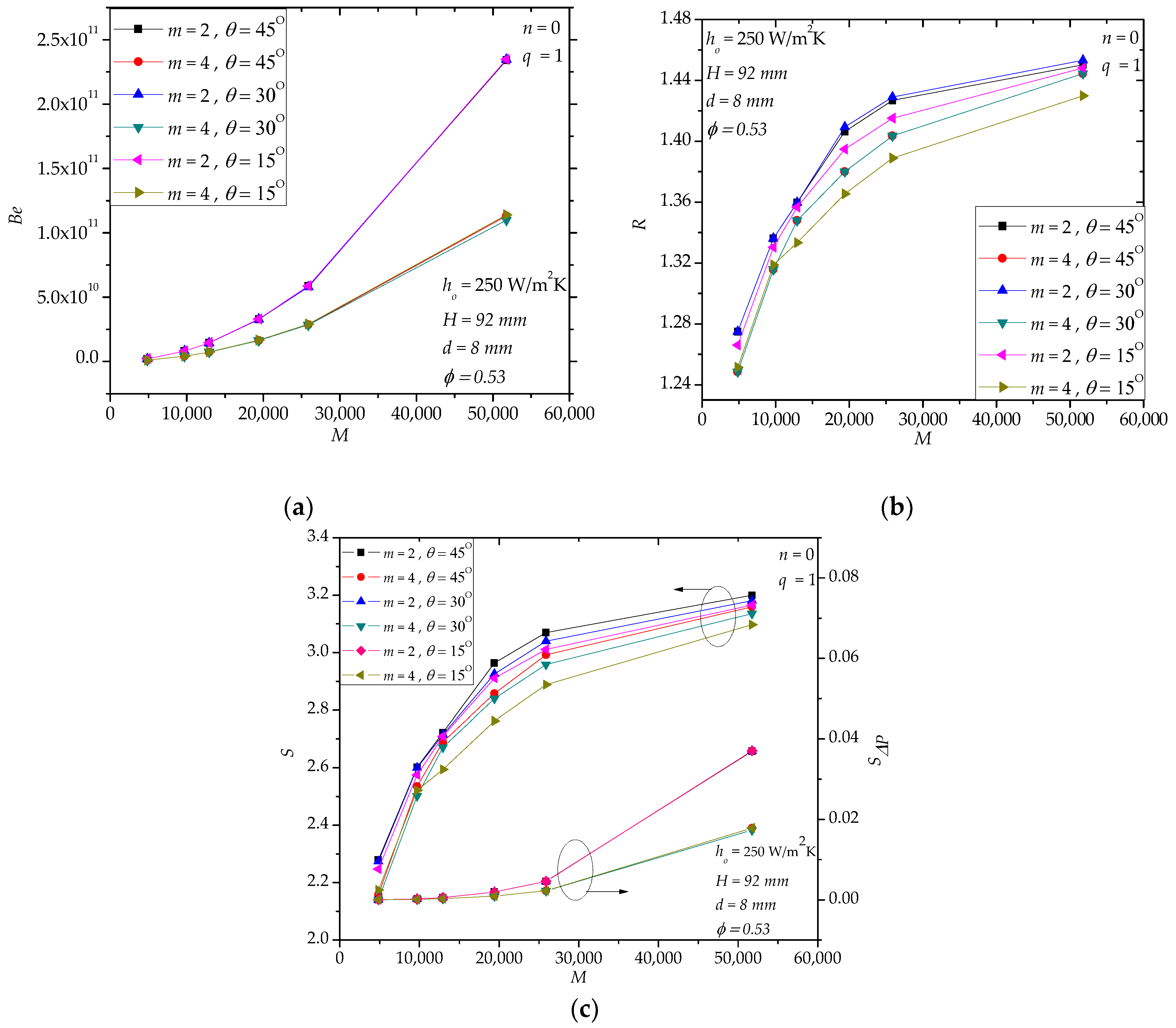
In hollow paddles, the diameter and the position angle of the flow holes influence the flow field and the stress distribution (or mechanical strength) of the shaft. Figure 7a shows that the diameter d affects Be significantly, especially when M is large, which means that the local loss of the molten salt flow is very important in the total pressure drop (also, cf. Figure 5d). Figure 7b shows that d has a weak effect on R. Actually, d only affects the local region near the inlet and outlet holes while the main heat transfer region (i.e., the internal fluid space) is nearly not influenced. In Figure 7c, when d decreases, SΔP/S increases especially for large M. For example, when M = 51,756, SΔP/S= 0.035, 0.011 and 0.007 for d = 6 mm, 8 mm and 9 mm, respectively. For the specified range in Figure 8, we notice that the effect of θ is weak. This observation encourages us to use larger θ to avoid stress concentration in the shaft. Actually, in Figure 8a (or Figure 8c), the curves of Be (or SΔP/S) for different position angles overlap each other.
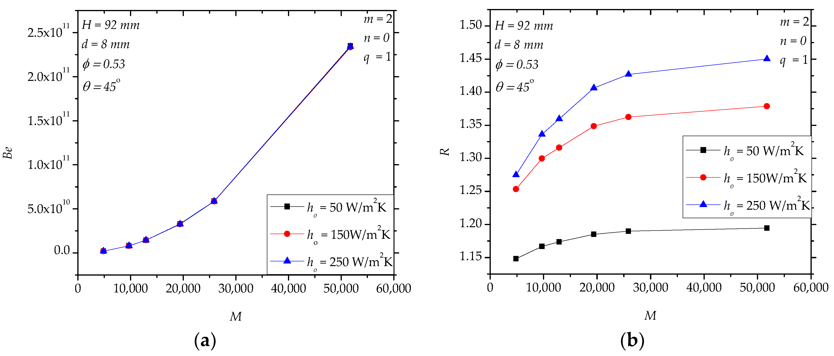
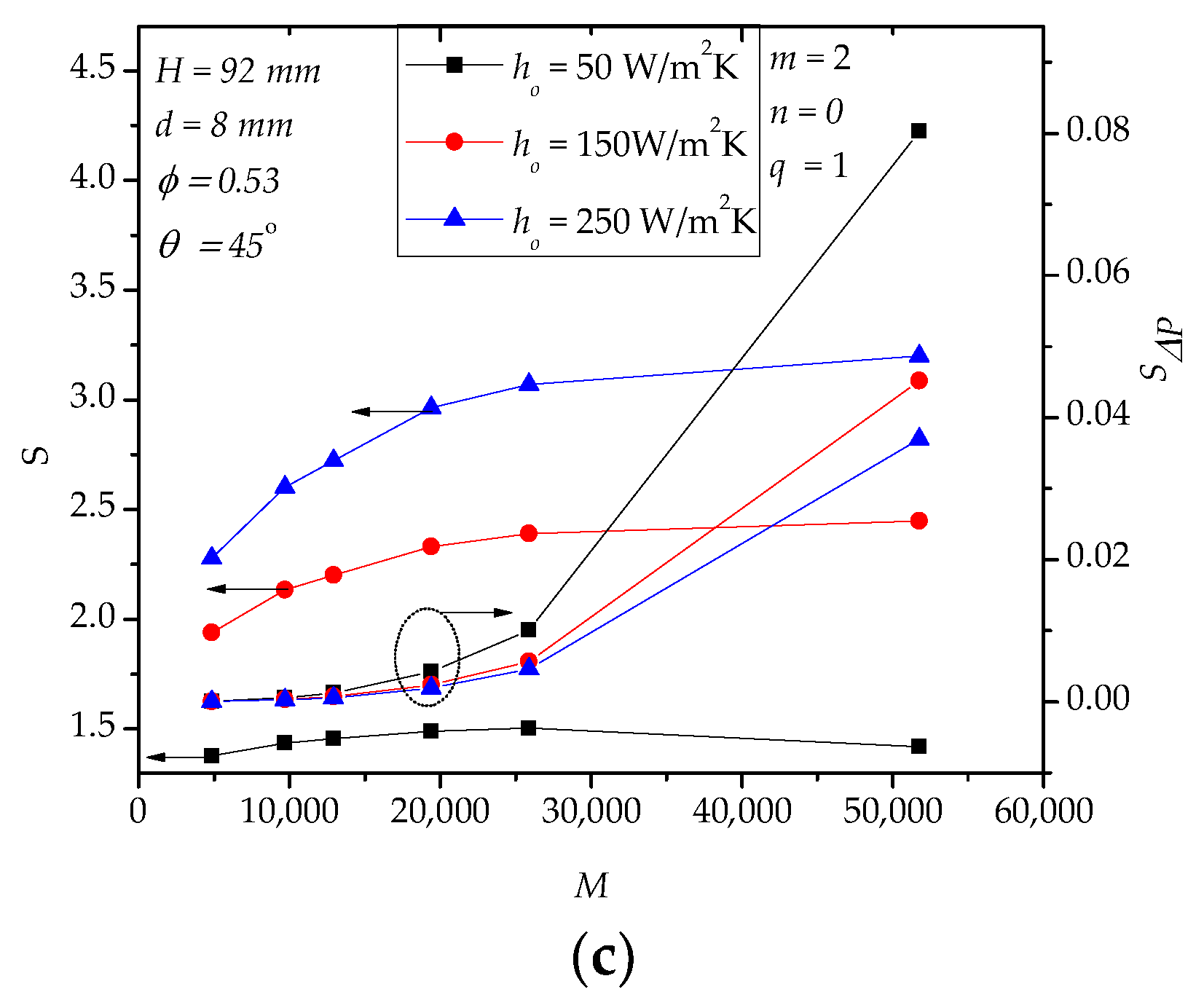
Although the shell-side material convective heat transfer coefficient (ho) does not affect Be (Figure 9a), it does influence R (Figure 9b). For a specified M, R increases with the increasing of ho. Even in the condition ho = 50 W/(m2K), R is greater than 1.15. In theory, when ho increases, the thermal resistance of conduction in the solid paddles becomes more dominant in which case hollow structures are more attractive. Because higher ho corresponds to a greater heat transfer rate, S is also larger (Figure 9c).
4.2. Case III
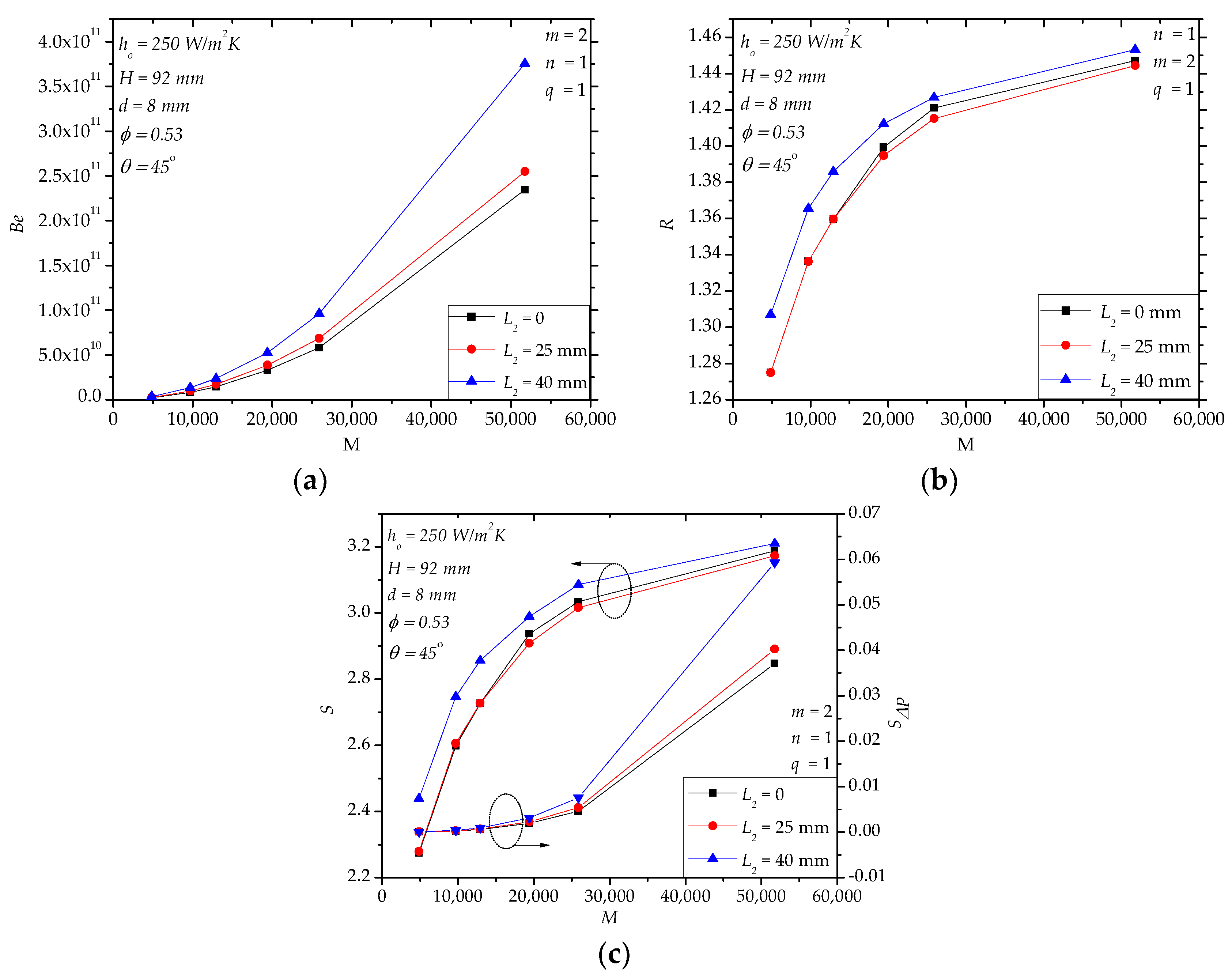
In Section 4.1, we verified the goodness of hollow structures in enhancing the heat transfer of the paddles. In this section, we further explore the flow field modification through internal baffles, aiming to bathe the fluid space as uniformly as possible. One simple way is to introduce one baffle (n = 1) near the outlet of the fluid space in order to narrow the corner region with poor flow near the outlet of the fluid space [23]. Increasing the height of the baffle (L2) obviously leads to higher pressure drop when M > 20,000 (Figure 10a). For L2 = 0 (n = 0, no baffle) and L2 = 25 mm, R is very close in the specified range of M, and for L2 = 40 mm, R is slightly greater (Figure 10b). For example, for M = 4849, R with L2 = 40 mm is 2.5% higher than that of L2 = 0 mm. The entropy generation rate S in Figure 10c displays a similar trend as R in Figure 10b. For large M (e.g., M > 25,000), Be increases with the increasing in L2, so SΔP increases, as well.
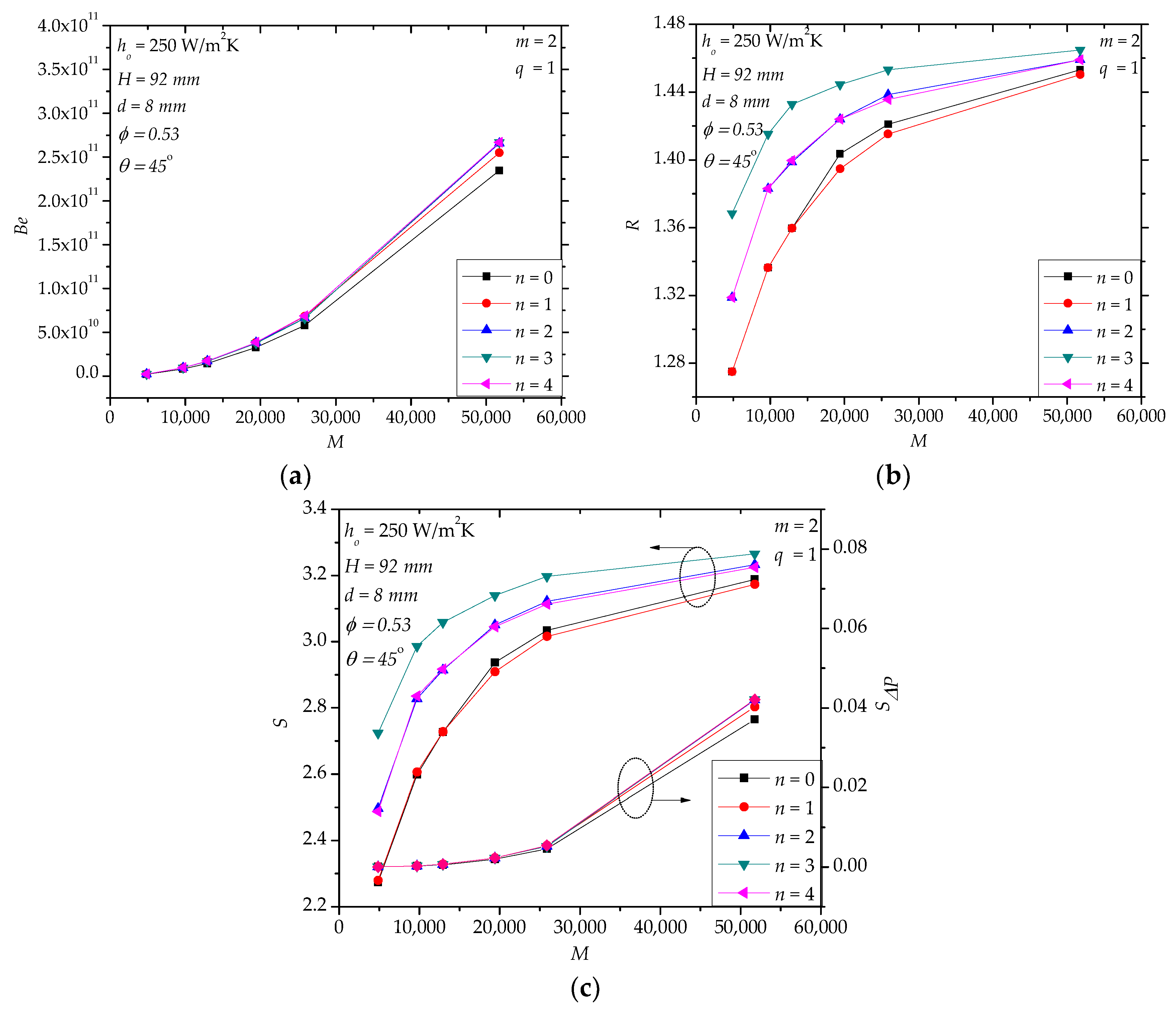
The effects of the number of the internal baffles (n) are shown in Figure 11. Here, we assume that the baffles are arranged uniformly and have a fixed height (L2 = 25 mm). In the range M < 20,000, n does not have a significant effect on Be (Figure 11a). When M > 20,000, there is limited gap in Be for n = 0 and n > 0. For n = 1~4, the gap of Be is small. From Figure 11b,c, we see that the effects of n are not monotonous. For example, for M = 9706, R for n = 3 is the largest and 6% greater than that for n = 0. For M = 9706, S for n = 3 is also the largest and 15% greater than that for n = 0. Realize that the present number of baffles (Figure 11) is few (n < 5). Much more baffles or three-dimensional baffles may generate plug flow that is good for convective heat transfer, but undoubtedly, the price is much higher pressure drop and manufacture cost.
4.3. Case IV
Figure 12 shows the simulation results of the four-hole design, i.e., two inlet flow holes and two outlet flow holes. Seen in Figure 12a, Be of the four-hole design is significantly less than that of the two-hole design in most of the specified range. When M increases, the gap between the two designs becomes larger. This is the obvious advantage of the four-hole design. However, R of the four-hole design reduces only 1.3~2.9% compared to that of the two-hole design in the specified range (Figure 12b). Note that Figure 12b is only a case study. For other conditions, the quantitative effect of the four-hole design may not be the same. Correspondingly, the entropy generation rate (S) of the four-hole design reduces 1.2~5.1% compared to that of the two-hole design in the specified range (Figure 12c). We know that the hollow paddles are welded on the outer surface of the hollow shaft, and the fluid space in the paddles is connected to that in the hollow shaft through the flow holes. More flow holes, corresponding to less pressure drop as shown in Figure 12, mean lower mechanical strength of the shaft. For sure, the four-hole design will weaken the mechanical strength of the shaft more heavily than the two-hole design, so the trade-off between the thermo-fluid design and the mechanical design is necessary. The analysis of the mechanical strength is beyond the scope of the present paper.
Theoretically, more holes (e.g., n = 6) is also possible. Note that in Figure 12a, c, the values of Be and SΔP/S are approximately the same along the range, so the curves cover each other.
4.4. Further Discussion
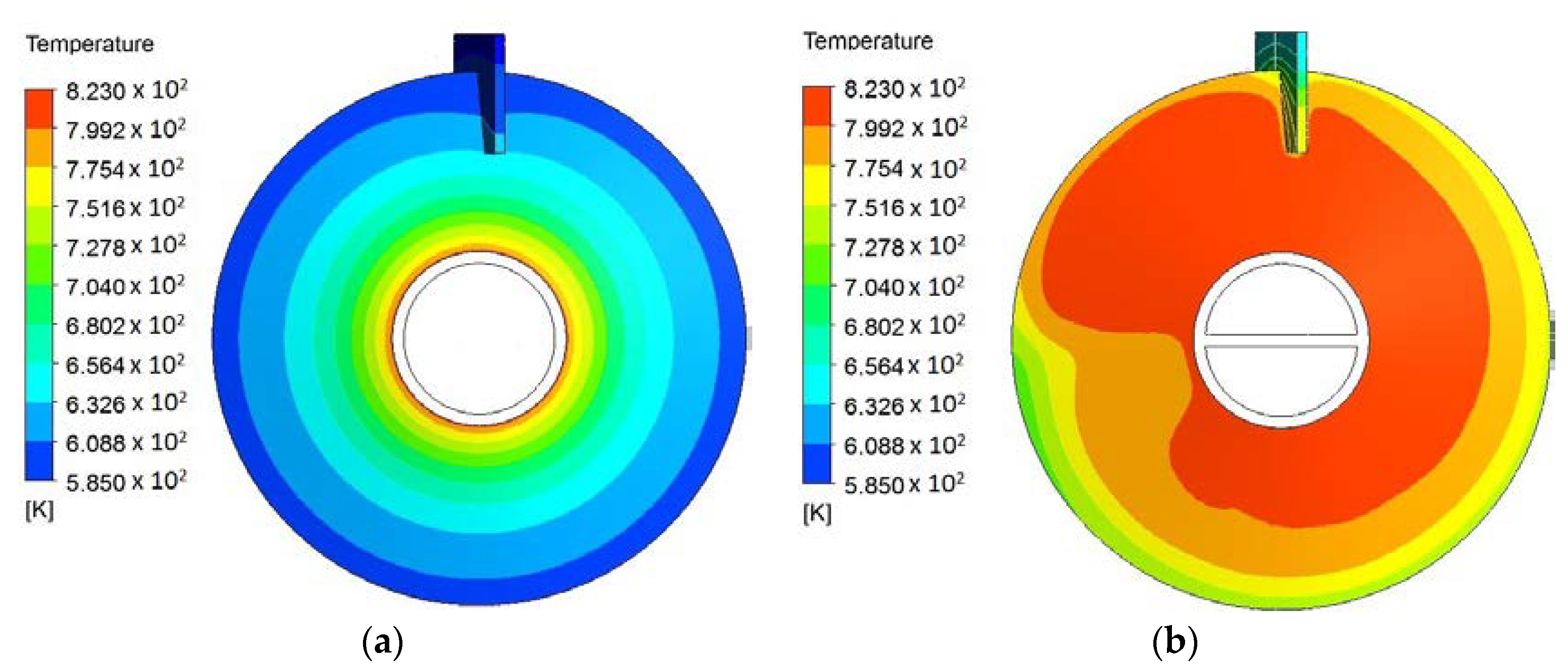
In the above sections, we showed the efficacy of using hollow paddles to enhance heat transfer. At the same time, the temperature uniformity of the paddles is also improved. Figure 13 provides an example of the temperature fields of the outer surfaces of two designs, namely one solid paddle (the reference design) and one hollow paddle. Apparently, the hollow paddle shows better temperature uniformity, and its average temperature approaches the inlet molten salt temperature more closely.
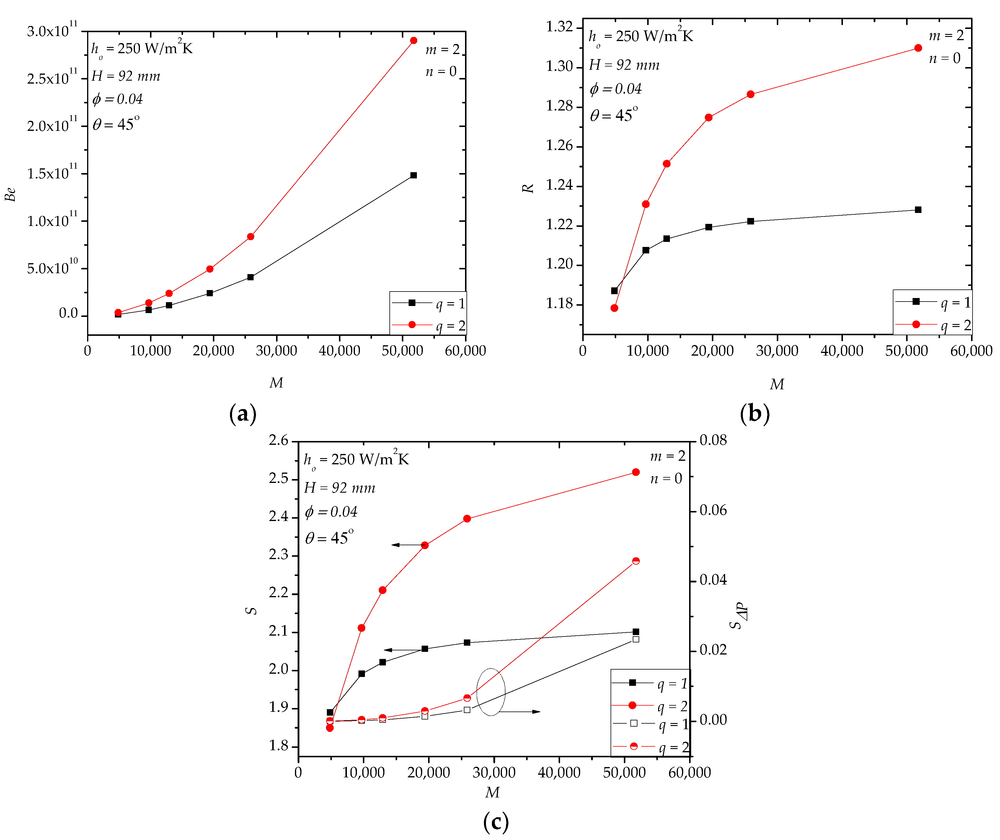
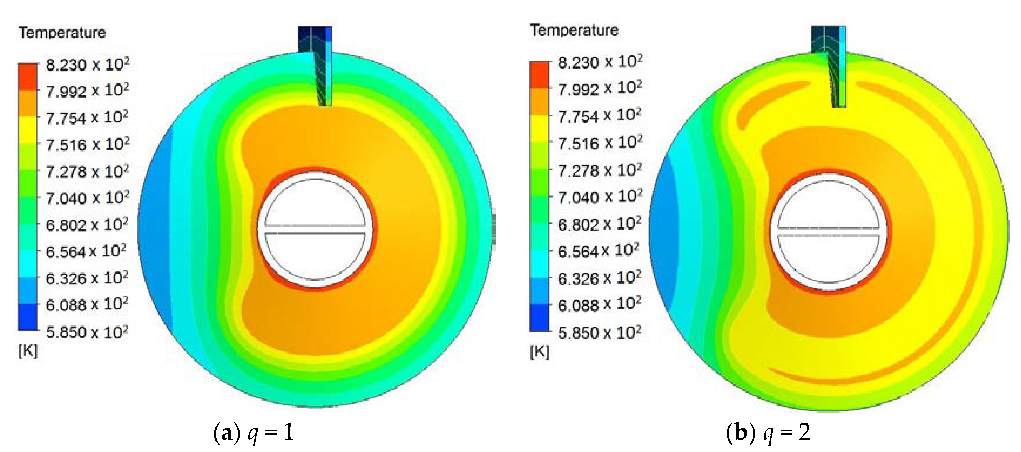
For hollow paddles with a small fluid volume ratio (also called vascular structures [21]), e.g., φ = 0.04, an alternative way of further improving the heat transfer rate is to optimize the distribution of the fluid channels, such as using multiple channels or multi-scale channels. In Section 4.1, for φ = 0.04, we used one tube with a diameter of 8 mm to form the fluid space. Here, in Figure 14, an example with two channels (q = 2) for φ = 0.04 is shown. In Figure 14a, Be for q = 2 is larger than that for q = 1. This is because the diameter of the two channels is less than that with only one channel. When M > 9706, R for q = 2 is greater than that for q = 1. When M < 9706, the gap between the two designs is limited. The entropy generation rate (S) shows a similar trend as R. Figure 15 shows the temperature fields of the designs with different q. The temperature uniformity of the design with q = 2 is better than that with q = 1.
5. Conclusions
In this paper, based on the widely-accepted CFD technique for single-phase flow and heat transfer, we used three-dimensional numerical simulations to investigate the fluid flow and heat transfer characteristics of high temperature molten salt flowing in single-leaf type hollow paddles. First, we showed that the heat transfer rate of the hollow paddles is significantly greater than that of the solid paddles. The heat transfer enhancement of the hollow paddles is attributed to convection replacing conduction partly in the paddles. The price of the heat transfer enhancement is additional pressure drop and a larger total entropy generation rate. The heat transfer-induced irreversibility is much larger than the pressure drop-induced irreversibility under the studied conditions.
Secondly, the effects of the main geometrical parameters and working conditions were revealed. Increasing the volume of the fluid space helps enhance the heat transfer, but there exists an upper limit. For a larger height of the paddles, the hollow paddles are more favorable compared to the solid paddles. The diameter of the flow holes influences the pressure drop strongly, but does not affect the heat transfer rate significantly. In the studied range, the effects of the position angles of the flow holes are weak. A larger material-side heat transfer coefficient corresponds to greater enhancement of heat transfer.
Finally, we discussed other possibilities of modifying the fluid flow and heat transfer, like using internal baffles to organize the flow field, using a four-hole design to replace the two-hole design or adopting multiple channels instead of a single channel for designs with small fluid volume. When the number of baffles is few (n < 5), the effects are limited. More flow holes reduce the pressure drop obviously. For the hollow paddles with small fluid volume, it is possible to increase the heat transfer rate with more fluid channels.
The complexity of the flow in hollow paddles lies on its three dimensionality, both radial and circumferential. Both local losses and distributed losses are important. The design selection depends on the trade-off among three factors, namely fluid flow (pressure drop), heat transfer and mechanical strength, although the mechanical strength was not included in this paper.
The present work reveals the goodness and badness of hollow paddles compared to solid paddles, which can help us make a decision about which will be selected in the real design of molten salt paddle heat exchangers. The research identifies the important factors that influence the pressure drop, the heat transfer rate and the total entropy generation rate and deepens our understanding of the heat transfer process for hollow paddles, e.g., from the viewpoint of irreversibility. It provides useful data (in dimensionless form) for design. The information in this paper is important and necessary for product design, manufacture and testing. Experimental work will be next.
Author Contributions
H.Z. proposed the research. T.R. performed the simulations and wrote the first version of the manuscript. All authors analyzed the results and revised the manuscript.
Funding
This research was funded by Shenzhen Science and Technology Commission Project No.: Z20170619; Taha Rajeh was supported by Chinese Government Scholarship (CSC Scholarship, CSC No.2016GXYG89).
Conflicts of Interest
The authors declare no conflict of interest.
Nomenclature
| Be | Dimensionless pressure drop, i.e., Bejan number |
| cp | Specific heat at constant pressure, J/(kgK) |
| C1ε, C2ε, Cµ | Constants, Equations (7) and (8) |
| d | Diameter of flow holes, mm or m |
| e | Specific total energy, J/kg |
| E | Total energy, J |
| h | Enthalpy, J/kg |
| ho | Shell-side material convective heat transfer coefficient, W/(m2K) |
| H | Paddle height, mm or m |
| k | Turbulent kinetic energy, m2/s2 |
| L, L1, ..., L5 | Dimensions, mm or m, Figure 3 |
| m | Number of flow holes |
| Mass flow rate, kg/s | |
| M | Dimensionless mass flow rate |
| n | Number of baffles |
| P | Pressure, Pa |
| Prt | Turbulent Prandtl number |
| q | Number of channels |
| Heat transfer rate, W | |
| R | Dimensionless heat transfer rate |
| s | Specific entropy, J/(kgK) |
| S | Dimensionless entropy generation rate |
| Entropy generation rate, W/K | |
| t | Paddle thickness, mm or m |
| T | Temperature, K or |
| To | Shell-side material temperature, K or |
| u | Velocity component, m/s |
| Fluctuating velocity component, m/s | |
| v | Velocity, m/s |
| V | Volume of a paddle, m3 |
| Vf | Fluid volume in a paddle, m3 |
| x | Coordinate component, mm or m |
| Greek symbols | |
| α | Thermal diffusivity, m2/s |
| Thermal expansion coefficient, 1/K | |
| δij | Unit tensor |
| ΔP | Pressure drop, Pa |
| ε | Dissipation rate, m2/s3 |
| θ | Position angle of flow holes |
| λ | Thermal conductivity, W/(mK) |
| µ | Dynamic viscosity, kg/(ms) |
| µt | Turbulent viscosity, kg/(ms) |
| ρ | Density, kg/m3 |
| σk, σε | Constants in Equations (6) and (7) |
| τ | Time |
| Volume ratio, Equation (16) | |
| Subscripts | |
| i, j, l | Coordinate direction |
| in | Inlet |
| out | Outlet |
| s | Solid |
| w | Wall |
References
- Arlabosse, P.; Chavez, S.; Lecomte, D. Method for thermal design of paddle dryers: Application to municipal sewage sludge. Dry. Technol. 2004, 22, 2375–2393. [Google Scholar] [CrossRef]
- Arlabosse, P.; Chavez, S.; Prevot, C. Drying of municipal sewage sludge: From a laboratory scale batch indirect dryer to the paddle dryer. Braz. J. Chem. Eng. 2005, 22, 227–232. [Google Scholar] [CrossRef]
- Deng, W.Y.; Yan, J.H.; Li, X.D.; Wang, F.; Lu, S.Y.; Chi, Y.; Cen, K.F. Measurement and simulation of the contact drying of sewage sludge in a Nara-type paddle dryer. Chem. Eng. Sci. 2009, 64, 5117–5124. [Google Scholar] [CrossRef]
- Zhang, H.; Liu, X.; Zhu, S.; Li, B. Sewage sludge flow and drying characteristics in paddle dryers. Defect Diffus. Forum 2013, 334–335, 365–368. [Google Scholar] [CrossRef]
- Charlou, C.; Milhé, M.; Sauceau, M.; Arlabosse, P. A new methodology for measurement of sludge residence time distribution in a paddle dryer using X-ray fluorescence analysis. Water Res. 2015, 69, 1–8. [Google Scholar] [CrossRef] [PubMed] [Green Version]
- Milhé, M.; Charlou, C.; Sauceau, M.; Arlabosse, P. Modeling of sewage sludge flow in a continuous paddle dryer. Dry. Technol. 2015, 33, 1061–1067. [Google Scholar] [CrossRef]
- Milhé, M.; Sauceau, M.; Arlabosse, P. Influence of operating parameters on sewage sludge drying in a paddle dryer: Design of experiments for the determination of hold-up and water content profiles. Dry. Technol. 2015, 33, 1276–1285. [Google Scholar] [CrossRef]
- Milhé, M.; Sauceau, M.; Arlabosse, P. Modeling of a continuous sewage sludge paddle dryer by coupling Markov chains with penetration theory. Appl. Math. Model. 2016, 40, 8201–8216. [Google Scholar] [CrossRef] [Green Version]
- Wu, Y.T.; Chen, C.; Liu, B.; Ma, C.F. Investigation on forced convective in heat transfer of molten salts in circular tubes. Int. Commun. Heat Mass Transf. 2012, 39, 1550–1555. [Google Scholar] [CrossRef]
- Ferng, Y.M.; Lin, K.Y.; Chi, C.W. CFD investigating thermal-hydraulic characteristics of FLiNaK salt as a heat exchange fluid. Appl. Therm. Eng. 2012, 37, 235–240. [Google Scholar] [CrossRef]
- Srivastava, A.K.; Vaidya, A.M.; Maheshwari, N.K.; Vijayan, P.K. Heat transfer and pressure drop characteristics of molten fluoride salt in circular pipe. Appl. Therm. Eng. 2013, 61, 198–205. [Google Scholar] [CrossRef]
- Zhang, Q.; Li, X.; Chang, C.; Wang, Z.; Liu, H. An experimental study: Thermal performance of molten salt cavity receivers. Appl. Therm. Eng. 2013, 50, 334–341. [Google Scholar] [CrossRef]
- Du, B.C.; He, Y.L.; Wang, K.; Zhu, H.H. Convective heat transfer of molten salt in the shell-and-tube heat exchanger with segmental baffles. Int. Commun. Heat Mass Transf. 2017, 113, 456–465. [Google Scholar] [CrossRef]
- Du, B.C.; He, Y.L.; Qiu, Y.; Liang, Q.; Zhou, Y.P. Investigation on heat transfer characteristics of molten salt in a shell-and-tube heat exchanger. Int. Commun. Heat Mass Transf. 2018, 96, 61–68. [Google Scholar] [CrossRef]
- Lu, J.; He, S.; Ding, J.; Yang, J.; Liang, J. Convective heat transfer of high temperature molten salt in vertical annular duct with cooled wall. Appl. Therm. Eng. 2014, 73, 1519–1524. [Google Scholar] [CrossRef]
- Chen, Y.S.; Tian, J.; Fu, Y.; Tang, Z.F.; Zhu, H.H.; Wang, N.X. Experimental study of heat transfer enhancement for molten salt with transversely grooved tube heat exchanger in laminar-transition-turbulent regimes. Appl. Therm. Eng. 2018, 132, 95–101. [Google Scholar] [CrossRef]
- Carasik, L.B.; Shaver, D.R.; Haefner, J.B.; Hassan, Y.A. Steady RANS methodology for calculating pressure drop in an in-line molten salt compact cross flow heat exchanger. Prog. Nuclear Energy 2017, 101, 209–223. [Google Scholar] [CrossRef]
- Chen, X.; Wang, C.; Wu, Y.; Liu, B.; Ma, C. Characteristics of the mixed convection heat transfer of molten salts in horizontal square tubes. Sol. Energy 2017, 147, 248–256. [Google Scholar] [CrossRef]
- Fu, W.; Lin, H.; Liu, X.; Zhang, H. Constructal design of molten salt flow and heat transfer in horizontal hollow disc-shaped heaters. In Proceedings of the Constructal Law & Second Law Conference, Bucharest, Romania, 14–16 May 2017; Morega, A., Lorente, S., Eds.; The Publishing House of the Romanian Academy: Bucharest, Romania, 2017; pp. 171–187. [Google Scholar]
- Du, J.; Shao, F.; Du, W.; Zhang, H.; Liu, X. Review on high temperature molten salt heat exchangers and applications. Sol. Energy 2015, 8, 35–40, 55. (In Chinese) [Google Scholar]
- Bejan, A.; Lorente, S. Design with Constructal Theory, 1st ed.; Wiley & Sons Inc.: Hoboken, NJ, USA; New York, NY, USA, 2008; pp. 329–371. ISBN 978-0-471-99816-7. [Google Scholar]
- Zhang, K.; Du, J.; Liu, X.; Zhang, H. Molten salt flow and heat transfer in paddle heat exchangers. Int. J. Heat Technol. 2016, 34, 43–50. [Google Scholar] [CrossRef]
- Ji, L.; Liu, X.; Zhang, H. Steady and dynamic thermo-fluid performance of molten salt in paddle heat exchangers. Int. J. Fluid Mech. Res. 2016, 43, 472–488. [Google Scholar] [CrossRef]
- Du, J. Research on High Temperature Molten Salt in Paddle Heat Exchangers. Master’s Thesis, Nanjing University of Science and Technology, Nanjing, China, 2015. (In Chinese). [Google Scholar]
- Wang, W.; Zhang, H.; Liu, X. Research and application prospects of coal slime in paddle dryers. Ind. Boil. 2015, 149, 34–36. (In Chinese) [Google Scholar]
- Pope, S.B. Turbulent Flows, 1st ed.; Cambridge University Press & Beijing World Publishing Corporation: Cambridge, UK, 2010; pp. 14–18, 373–385. ISBN 978-7-5100-0573-2. [Google Scholar]
- Tufeu, R.; Petitet, J.P.; Denielou, L.; Le Neindre, B. Experimental determination of the thermal conductivity of molten pure salts and salt mixtures. Int. J. Thermophys. 1985, 6, 315–330. [Google Scholar] [CrossRef]
- ANSYS Fluent. User’s Manual; Version 14.5; Fluent Inc.: Canonsburg, PA, USA, 2012. [Google Scholar]
- Bejan, A. Entropy Generation Minimization, 1st ed.; CRC Press: Boca Raton, FL, USA, 1996; pp. 21–40. ISBN 0-8493-9651-4. [Google Scholar]
- Çengel, Y.A.; Boles, M.A. Thermodynamics: An Engineering Approach, 5th ed.; McGraw-Hill Education: New York, NY, USA, 2006; pp. 378–382, ISBN 0072884959, 9780072884951. [Google Scholar]
Figure 1.
Hollow paddles: (a) single-leaf type; and (b) two-leaf type.

Figure 2.
Cross-section of a single-shaft and single-leaf type paddle heat exchanger.

Figure 3.
Candidate designs: (a) Case I, solid paddle; (b) Case II, hollow paddle with two flow holes, (c) Case III, hollow paddle with two flow holes and internal baffles; (d) Case IV, hollow paddle with four flow holes.
Figure 3.
Candidate designs: (a) Case I, solid paddle; (b) Case II, hollow paddle with two flow holes, (c) Case III, hollow paddle with two flow holes and internal baffles; (d) Case IV, hollow paddle with four flow holes.

Figure 4.
The effects of the fluid volume in hollow paddles. (a): Be; (b): R; (c): S, SΔP.

Figure 5.
Pressure distribution (Case II, m = 2, n = 0, q = 1, ho = 250 W/m2K, H = 92 mm, d = 8 mm, θ = 45°, M = 25,881).
Figure 5.
Pressure distribution (Case II, m = 2, n = 0, q = 1, ho = 250 W/m2K, H = 92 mm, d = 8 mm, θ = 45°, M = 25,881).


Figure 6.
The effects of the paddle height (H). (a): Be; (b): R; (c): S, SΔP.


Figure 7.
The effects of the diameter of the flow holes. (a): Be; (b): R; (c): S, SΔP.

Figure 8.
The effects of the position angle of the flow holes. (a): Be; (b): R; (c): S, SΔP.

Figure 9.
The effects of the shell-side material convective heat transfer coefficient (ho). (a): Be; (b): R; (c): S, SΔP.
Figure 9.
The effects of the shell-side material convective heat transfer coefficient (ho). (a): Be; (b): R; (c): S, SΔP.


Figure 10.
The effects of the geometry of the outlet baffle (L2). (a) Be; (b) R; (c) S, SΔP.

Figure 11.
The effects of the number of baffles. (a) Be; (b) R; (c) S, SΔP.

Figure 12.
The effects of the number of the flow holes (m). (a) Be; (b) R; (c) S, SΔP.

Figure 13.
Temperature fields of outer surfaces: (a) solid paddle; (b) hollow paddle (m = 2, n = 0, q = 1, ho = 250 W/(m2K), H = 92 mm, d = 8 mm, φ = 0.53, θ = 45°, M = 25,881).
Figure 13.
Temperature fields of outer surfaces: (a) solid paddle; (b) hollow paddle (m = 2, n = 0, q = 1, ho = 250 W/(m2K), H = 92 mm, d = 8 mm, φ = 0.53, θ = 45°, M = 25,881).

Figure 14.
Two fluid channels in the paddles. (a) Be; (b) R; (c) S, SΔP.

Figure 15.
Temperature fields of outer surfaces for different channels (m = 2, n = 0, ho = 250 W/m2K, H = 92 mm, d = 8 mm, φ = 0.04, θ = 45°, M = 25,881).
Figure 15.
Temperature fields of outer surfaces for different channels (m = 2, n = 0, ho = 250 W/m2K, H = 92 mm, d = 8 mm, φ = 0.04, θ = 45°, M = 25,881).


Table 1.
The boundary conditions.
| Paddle Structure | Boundary Condition | |
|---|---|---|
| Fluid | Inlet | Tin = 550 °C |
| Outlet | Pout = 0 Pa | |
| Shell-side material | Shell-side material | To = 300 °C, ho = 250 W/(m2K) |
| Solid | Inside surfaces of shaft | Tw = 550 °C |
| End-wall surfaces of shaft | Adiabatic | |
| Property | ρ (kg/m3) | cp (J/(kg K)) | λ (W/(m K)) | μ (kg/(m s)) |
|---|---|---|---|---|
| Molten salt | 1944 | 1559.886 | 0.908 | 0.0012 |
| Stainless steel 316L | 8000 | 500 | 21.5 |
Table 3.
Mesh independence checking (Case II, = 0.39 kg/s, ho = 250 W/(m2K), m = 2, n = 0, q = 1, H = 92 mm, d = 8 mm, φ = 0.53, θ = 45°).
Table 3.
Mesh independence checking (Case II, = 0.39 kg/s, ho = 250 W/(m2K), m = 2, n = 0, q = 1, H = 92 mm, d = 8 mm, φ = 0.53, θ = 45°).
| Number of elements | 7,539,242 | 6,825,664 | 6,094,076 | 5,003,249 | 4,004,098 |
| Number of nodes | 1,866,142 | 1,731,115 | 1,566,281 | 1,318,141 | 1,063,456 |
| Pressure drop ΔP (Pa) | 30,997 | 30,922 | 31,131 | 31,430 | 28,020 |
| Heat transfer rate(W) | 2836 | 2841 | 2848 | 2848 | 2942 |
Table 4.
Cases of hollow paddles with different φ (m = 2, n = 0, q = 1, H = 92 mm, d = 8 mm, θ = 45°).
Table 4.
Cases of hollow paddles with different φ (m = 2, n = 0, q = 1, H = 92 mm, d = 8 mm, θ = 45°).
| φ | Paddle Type | Geometry Description |
|---|---|---|
| 0 | Solid | Reference: no fluid space in the paddle. |
| 0.04 | Hollow | The fluid space is a tube of 8 mm diameter in the paddle. |
| 0.22 | Hollow | t = 20 mm |
| 0.46 | Hollow | t = 6 mm |
| 0.53 | Hollow | t = 3 mm |
© 2018 by the authors. Licensee MDPI, Basel, Switzerland. This article is an open access article distributed under the terms and conditions of the Creative Commons Attribution (CC BY) license (http://creativecommons.org/licenses/by/4.0/).
Share and Cite
MDPI and ACS Style
Rajeh, T.; Tu, P.; Lin, H.; Zhang, H. Thermo-Fluid Characteristics of High Temperature Molten Salt Flowing in Single-Leaf Type Hollow Paddles. Entropy 2018, 20, 581. https://doi.org/10.3390/e20080581
AMA Style
Rajeh T, Tu P, Lin H, Zhang H. Thermo-Fluid Characteristics of High Temperature Molten Salt Flowing in Single-Leaf Type Hollow Paddles. Entropy. 2018; 20(8):581. https://doi.org/10.3390/e20080581
Chicago/Turabian StyleRajeh, Taha, Ping Tu, Hua Lin, and Houlei Zhang. 2018. "Thermo-Fluid Characteristics of High Temperature Molten Salt Flowing in Single-Leaf Type Hollow Paddles" Entropy 20, no. 8: 581. https://doi.org/10.3390/e20080581
Note that from the first issue of 2016, this journal uses article numbers instead of page numbers. See further details here.