Article

Electro‐Quasistatic Analysis of an Electrostatic Induction Micromotor Using the Cell Method

by
José Miguel Monzón-Verona
1,
Francisco Jorge Santana-Martín
1,
Santiago García–Alonso
2 and
Juan Antonio Montiel-Nelson
2,*
1
University of Las Palmas de Gran Canaria, Department of Electrical Engineering, Institute for Applied Microelectronics, Campus Univ. de Tafira s/n, 35017 Las Palmas de Gran Canaria, Spain
2
University of Las Palmas de Gran Canaria, Department of Electronic Engineering and Automatic, Institute for Applied Microelectronics, Campus Univ. de Tafira s/n, 35017 Las Palmas de Gran Canaria, Spain
*
Author to whom correspondence should be addressed.
Sensors 2010, 10(10), 9102-9117; https://doi.org/10.3390/s101009102
Submission received: 16 August 2010 / Revised: 29 September 2010 / Accepted: 30 September 2010 / Published: 11 October 2010
(This article belongs to the Section Chemical Sensors)

Abstract

:
An electro-quasistatic analysis of an induction micromotor has been realized by using the Cell Method. We employed the direct Finite Formulation (FF) of the electromagnetic laws, hence, avoiding a further discretization. The Cell Method (CM) is used for solving the field equations at the entire domain (2D space) of the micromotor. We have reformulated the field laws in a direct FF and analyzed physical quantities to make explicit the relationship between magnitudes and laws. We applied a primal-dual barycentric discretization of the 2D space. The electric potential has been calculated on each node of the primal mesh using CM. For verification purpose, an analytical electric potential equation is introduced as reference. In frequency domain, results demonstrate the error in calculating potential quantity is neglected (<3‰). In time domain, the potential value in transient state tends to the steady state value.

Graphical Abstract

1. Introduction

Electromagnetic laws were formulated ab initio using global quantities, such as charge, current, electric and magnetic flux, electromotive and magnetomotive force. Kirchoff’s network equations were also stated using global quantities, potential and current.
After Maxwell’s publication, electromagnetic laws have been commonly written using differential equations. Because differential formulation is restricted to homogeneous regions—material homogeneity—heterogeneous domains are broken in homogeneous subdomains plus jump conditions. The discrete formulation of differential equations requires a discretization method, such as finite difference, finite element, boundary element, among others.
As an alternative, a direct Finite Formulation (FF) of the electromagnetic laws based on global variables accepts material discontinuities, as is the case of the micromotor interface region, which is the surface of the resistive metal sheet of the mobile part of the micromotor in contact with the air (see Figure 1). In a direct FF [13], an algebraic system of equations is directly written, avoiding the discretization process. The corresponding numerical method is known as the Cell Method (CM) [46]. The present paper applies this method to the simulation and analysis of an electrostatic induction micromotor.
The main benefit of CM is the remarkable simplification of its theoretical formulation, and therefore, the obtained equation system. The CM algebraic equation system is equivalent to the obtained in FEM using affine approximation of the electric potential inside of the triangle mesh. CM simplification is because physical laws of the electrostatic induction micromotor are expressed directly by a set of algebraic equations. However, in FEM, the algebraic equations are obtained after a discretization process using differential equations. Thus, CM requires two steps less than FEM to obtain the same algebraic system of equations.
The fundamental principle of CM is the use of finite or global measurable quantities. In the micromotor analysis, we use the voltage along a line instead of the electric field in a point. Therefore, we don’t use those quantities that are defined through a mathematical limit process as standard operations of gradient, curl and divergence. Note that a mathematical limit process involves operational difficulties in some conditions—such as discontinuities in the electrical field in the interface, due to the superficial conductivity. They are not adequate for numerical processing. Because of this, FEM involves two additional steps: first, Green’s theorem is applied; and second, the first order interpolation function of Whitney elements is used. The last step introduces a tangential continuity of the field magnitudes in the edge of the elements and, however, allows discontinuity in the normal component. The constitutive equations in CM formulation have a deep geometric interpretation based in the geometry of primal and dual meshes. This interpretation facilitates the incorporation of two types of physical properties, volumetric and superficial with electrical conductivity.
Nowadays, the design and implementation of a micromotor using MEMS technology is a great challenge [79]. For this purpose, we have developed some tools based on FF to simulate the electromagnetic fields of an electrostatic induction micromotor. In [10], we introduce the analytical equations for an electrostatic induction micromotor. References [1115] provide state-of-the-art contributions in discrete electromagnetism and electrostatic formulation. In [12], its authors apply CM for computing the capacitance of a transmission line in presence of non homogeneous media. Reference [13] deals with a general application of CM to solve both isotropic and anisotropic electrostatic problem. In [12,13], the dielectric is characterized by a constitutive permittivity matrix—volumetric property—; the electric conductivity is neglected at the whole domain.
In this work, for an electrostatic micromotor, the superficial conductivity at the interface of the mobile part plays a key role. In addition, we consider a volumetric conductivity at the mobile part. Figure 1 illustrates both superficial and volumetric conductivity, σS and σb, respectively. As a consequence, time dependent terms are considered in our finite formulation problem, and therefore, we carry out both frequency and transitory analysis.
The analyzed micromotor is a simple linear electrostatic induction micromachine constituted by two parallel plates—mobile part and stator—isolated by a dielectric [8]. The distance between plates is 6 μm. Figure 1 summarizes the operation mode of the micromachine. Table 1 shows the nomenclature and Table 2 presents the physical and geometrical parameters of the micromachine. Our work is focused in the linear micromachine due to the great simplicity of analytical equations. The linear micromachine is the unfolding of a rotating electric micromachine. Consequently, the conclusions obtained for the linear micromachine are directly generalized to the rotating one [16].
The paper is organized as follows. Section 2 contains the reformulation of the field laws in a direct FF for the micromotor. Initially, we introduce global variables by analyzing physical quantities in order to make explicit the maximum of information. Both topological and constitutive equations are explained in detail. Then, we present the final global equation of the electrostatic induction micromotor. In Section 3, we provide an analytical equation of the electric potential—global variable—at the interface of the micromotor. For verification purpose, electric potential values are calculated by solving field equations with CM. Both frequency and time domain comparisons are introduced. Finally, Section 4 provides conclusions of the work.

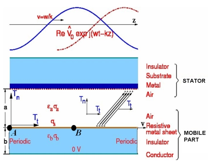
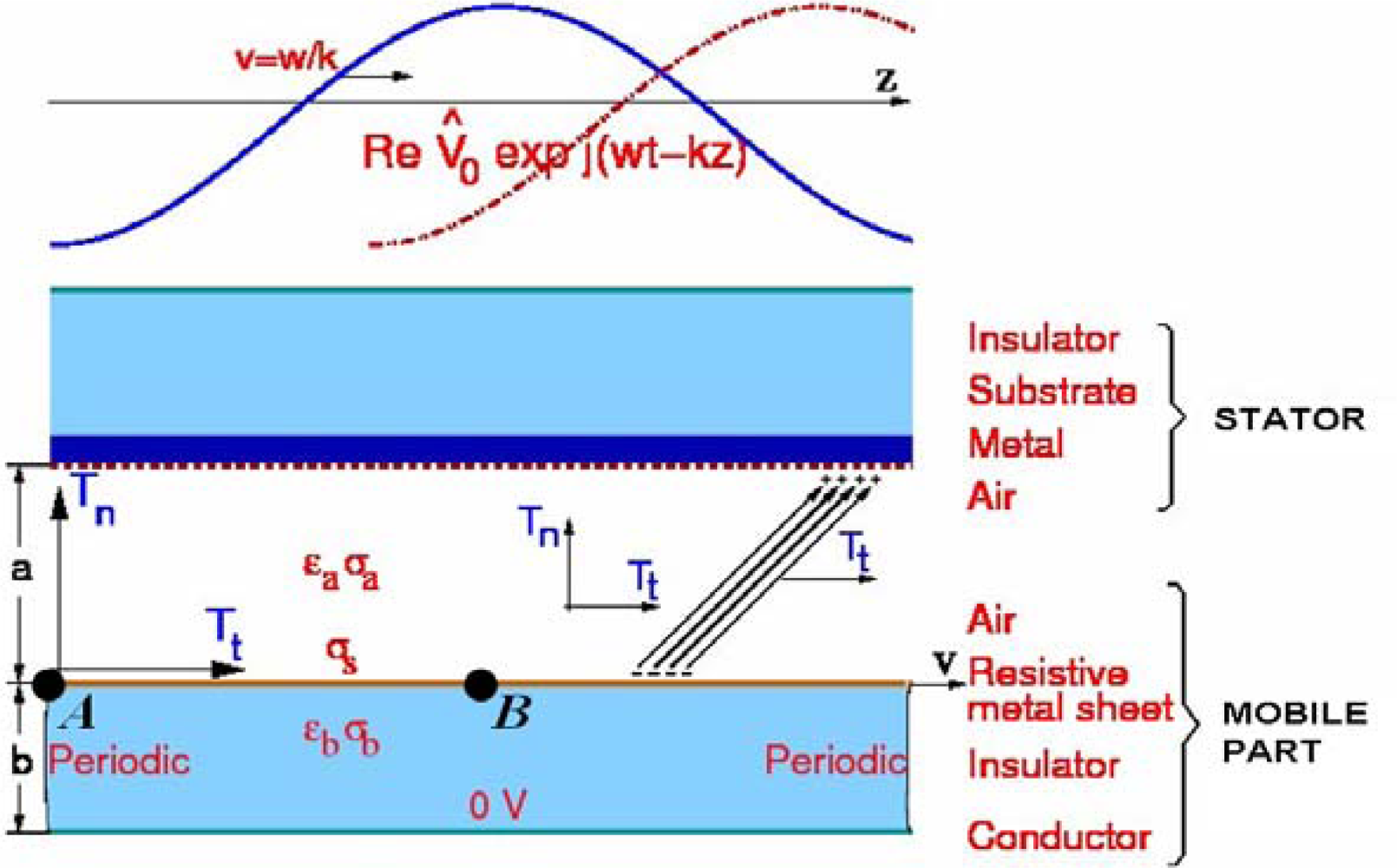
2. Finite Formulation for the Micromotor

The reformulation of field laws in a direct FF begins with an analysis of physical quantities. Physical measurements deal with global variables against field variables. In differential formulation, field variables are utilized because the notion of derivative refers to a point function. Contrariwise, global variables refer to a system, at a space or time element—global variables concern to oriented geometrical elements like points, lines, surfaces, volumes and time elements like instant and interval.
According to FF, global variables are also classified into configuration, source, and energy variables [1]. The configuration variables describe the configuration of the field without the intervention of the material parameters. The source variables describe the source of the field without involving the material parameters. The energy variables are the product between a configuration and source variable.
CM requires the use of a pair of oriented cell complexes, one dual to each other, endowed with inner orientation (see I,J,K cell in Figure 2) and outer orientation (see 1,2,3,...,11 cell in Figure 2). Figure 2 illustrates the corresponding dual cell complexes. They were obtained from the barycentric subdivision [11].
According to electromagnetism FF, the first principle [3] says that the configuration variables are naturally associated with space and time elements of a primal cell complex endowed with inner orientation, while the source variables are associated with space and time elements of a dual cell complex endowed with outer orientation. The second principle [3] says that in every physical theory there are physical laws that link global variables referred to an oriented space-time element with others referred to its oriented boundary.

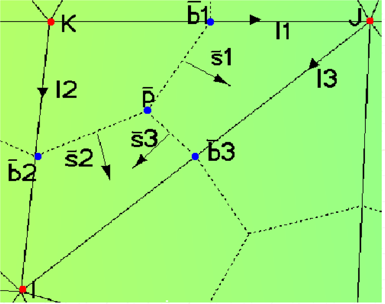
2.1. Topological Equation of the Micromotor in Discrete Form

The field equation of the micromotor is enforced, on the cell complexes, in exact discrete form by using incidence matrices G, C and D. They are denoted as edges-nodes, faces-edges, and volumes-faces, respectively, for the oriented primal cell complex. Let matrices , and denote the node-edges, edges-faces, and faces-volumes, respectively, for the oriented dual cell complex. These matrices are viewed as discrete counterparts of the differential operator gradient, curl, and divergence [5,12,14].
The following equations represent the counterparts of the differential Maxwell′s laws.
Gauss law:
D ˜ ψ ˜ = Q ˜
where ψ͂ is the electric flux vector associated to the dual faces and the electric charge vector associated to the dual volumes.
Faraday law (for quasi–electrostatic conditions):
CU = 0
U = GV
where V is the electric potential associated to the primal nodes and U the voltage vector associated to the primal edges.
Charge conservation law:
D ˜ I ˜ + D ˜ d ψ ˜ dt = 0
where Ĩ is the electric current vector associated to the dual faces.
The duality between the oriented primal and dual space cell complexes leads, in general, to the following relationships [14,17]:
D ˜ = G T
C ˜ = C T
G ˜ = D T

2.2. Constitutive Equation of the Micromotor in Discrete Form

While field equations in direct FF describe the physical laws exactly, the constitutive equations describe the physical laws approximately. For the micromotor the integral potential and flux state variables, which are allocated on two different cell complexes, are related to each other by the constitutive material equations. These equations are matrix equations. They contain the average information of the material and grid dimension [6,11,12,1820].
Since Equations (1)(4) only contain topological information, the discretization error comes from the discrete constitutive material equations.
Volumetric properties—volumetric conductivity and permittivity—and superficial properties—superficial conductivity—are considered constitutive equations of the micromotor. Therefore, two classes of cells for the discrete constitutive material equations rise. For a bidimensional form, the volume cell and face cell are transformed in face cell and edge cell, respectively.
The constitutive equations for a simple primal–dual cell (see Figure 3), are as follows:
I ˜ e = M U σ e e
ψ ˜ e = M U ɛ e e
The expressions for the face element are:
ψ ˜ e = ( ψ ˜ 1 ψ ˜ 2 ψ ˜ 3 ) T
I ˜ e = ( I ˜ 1 I ˜ 2 I ˜ 3 ) T
and for the edge element:
U e = ( U 1 U 2 U 3 ) T
M σ V e and M ɛ V e are the volumetric conductivity and the permittivity matrices, respectively:
M σ V e = 1 / 3 S ˜ e σ e ( A e + B e + C e )
M ɛ V e = 1 / 3 S ˜ e ɛ e ( A e + B e + C e )
Ae, Be and Ce depend on geometry of the primal cell and are expressed as follows:
A e = 1 Δ 1 [ 0 I 3 y I 2 y 0 I 3 x I 2 x ]
B e = 1 Δ 2 [ I 3 y 0 I 1 y I 3 x 0 I 1 x ]
C e = 1 Δ 3 [ I 2 y I 1 y 0 I 2 x I 1 x 0 ]
Δ1, Δ2, and Δ3 expressions are:
Δ 1 = I 2 x I 3 y I 2 y I 3 x
Δ 2 = I 1 x I 3 y I 1 y I 3 x
Δ 3 = I 1 x I 2 y I 1 y I 2 x
(I1x, I1y), (I2x, I2y) and (I3x, I3y), are vectors associated to the primal edges:
( I 1 x , I 1 y ) = ( x j x k , y j y k )
( I 2 x , I 2 y ) = ( x i x k , y i y k )
( I 3 x , I 3 y ) = ( x i x j , y i y j )
where (xi, yi) are the coordinates associated to the nodes of the triangle of reference (see Figure 3). e is expressed as follows:
S ˜ e = ( S ˜ 1 x S ˜ 1 y S ˜ 2 x S ˜ 2 y S ˜ 3 x S ˜ 3 y ) = ( S ˜ 1 S ˜ 2 S ˜ 3 )
The permittivity and conductivity tensors are:
ɛ e = ( ɛ 11 0 0 ɛ 22 )
σ e = ( σ 11 0 0 σ 22 )
where U1, U2 and U3 are the voltage associated to the edges I1, I2 and I3 (see Figure 3), respectively; ψ͂1, ψ͂2, ψ͂3 and Ĩ1, Ĩ2, Ĩ3 are the electric flow and the electric intensity associated to the surfaces 1, 2 and 3, respectively, of the simple dual cell (see Figure 3).
M σ s e is the superficial conductivity matrix, and it is expressed as:
M σ S e = t e σ S e l e
where σ S e is the superficial conductivity and le is the length of an element (i, j).
The components of the vectors associated to the dual surfaces 1, 2 and 3 (see Figure 3), are:
S ˜ 1 = t ( P b 1 y , P b 1 x )
S ˜ 2 = t ( P b 2 y , P b 2 x )
S ˜ 3 = t ( P b 3 y , P b 3 x )
where t stands for the thickness of the model, (Pb1x, Pb1y), (Pb2x, Pb2y) and (Pb3x, Pb3y) are vectors at the barycentric of the reference triangle:
( P b 1 x , P b 1 y ) = ( b 1 x P ˜ x , b 1 y P ˜ y )
( P b 2 x , P b 2 y ) = ( b 2 x P ˜ x , b 2 y P ˜ y )
( P b 3 x , P b 3 y ) = ( b 3 x P ˜ x , b 3 y P ˜ y )
The centers (1, 2 3) of the edges 1, 2, and 3, respectively, are the coordinates:
( b 1 x , b 1 y ) = ( x k + x j 2 , y k + y j 2 )
( b 2 x , b 2 y ) = ( x i + x k 2 , y i + y k 2 )
( b 3 x , b 3 y ) = ( x i + x j 2 , y i + y j 2 )
Point is defined as:
( P ˜ x , P ˜ y ) = ( x i + x j + x k 3 , y i + y j + y k 3 )

2.3. Final Global Equation of the Micromotor

We obtain the local fundamental matrix by substituting in (4) the local constitutive Equations (8) and (9) and Gauss law (1), were U is expressed by means of (2) and (3):
G eT M σ e G e V e + G eT M ɛ e G e d V e dt = 0
where Ge is the incidence matrix of one element and is expressed as follows:
G e = i j k I 1 I 2 I 3 ( 0 1 1 1 0 1 1 1 0 )
and:
V e = ( V i V j V k ) T
For computational purpose, processing cells one by one is convenient. To obtain the global fundamental matrix all the local fundamental matrices on the reference cell are assembled (see Figure 3).
For a bidimensional formulation, in case of triangular elements under the hypothesis of uniform field and using a dual mesh with barycentric subdivision, the resulting matrix for one element is symmetric. Moreover, this matrix is coincident with the element matrix obtained with finite elements with affine approximation of the electric potential within the triangle [4,12]. Therefore, the resulting system of equations is coincident. To solve Equation (38), we have applied the following boundary conditions, one travelling wave on top, 0 V at bottom; and periodic boundary conditions on the left and right side (see Figure 1).

3. Results

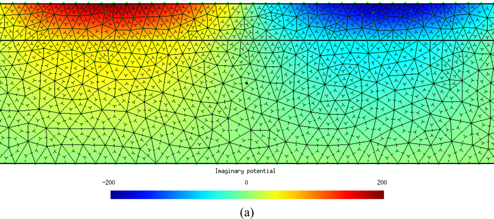
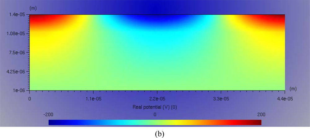
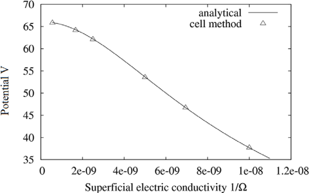
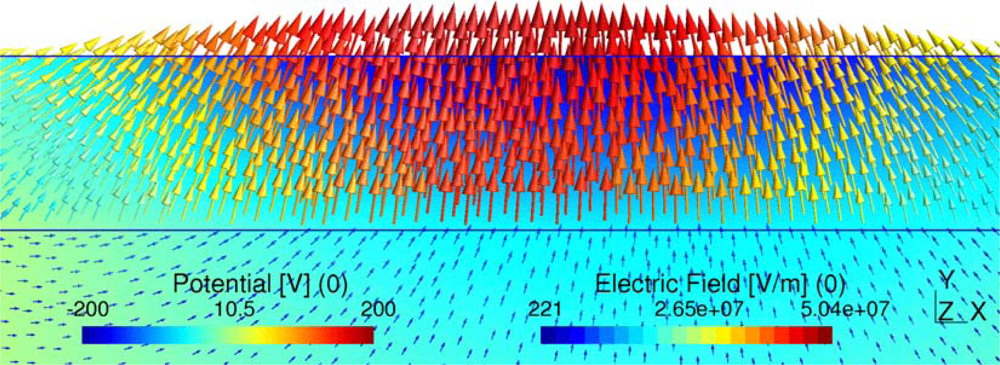
3.1. Discrete Field in Frequency Domain

First, Equation (38) is transformed to the frequency domain. Then, the operator substitutes to the operator ∂/∂t. In this way, Equation (38) is expressed in the following form:
G T M σ GV + jw G T M ɛ GV = 0
Next equation represents the analytical electric potential at the interface of the micromotor [10]. This is the reference equation for the FF verification.
Φ b = V 0 sinh ( k a ) σ a σ eff + ɛ a ɛ eff ω S j ( 1 + ɛ eff σ eff ω S j )
where:
σ eff = σ a coth ( ka ) + coth ( kb ) σ b + σ S k
ɛ eff = ɛ a k coth ( ka ) + ɛ b k coth ( kb )
We have calculated the potential at the interface, applying CM and the analytical equations, for five different values of the conductivity. The mismatch between the results obtained using analytical equations and the CM are neglected, as can be seen in Table 3. Figure 4(a) and 4(b) show the CM results of the potential for a superficial conductivity of 1/(1800·106) 1/Ω. Figure 4(a) and 4(b) represent the imaginary and real components of the scalar electric potential, respectively. Figure 4(a) also illustrates the primal and dual mesh.
Figure 5 represents the potential at the interface versus the conductivity. Typical maximum discrepancies are lower than 0.1%.
We have also calculated the electric field at the interface. CM results and analytical solution results are illustrated in Table 4 and Figure 6 for a superficial conductivity of 1/(600·106) 1/Ω. The error between the results obtained using analytical equations and the CM is neglected.
CM convergence has been guaranteed with the refining of the meshes of the micromotor as can be seen in Table 5. The interfacial electric potential has been obtained for a conductivity of 1/(1800·106) 1/Ω.

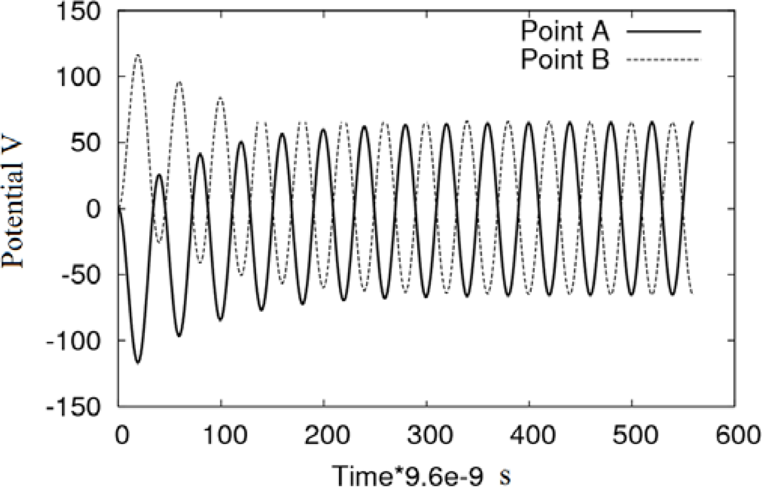
3.1. Discrete Field in Time Domain

In order to perform numerical calculations in time domain it is necessary to discretize the time axis for Equation (38). The θ-method of integration [2123] is widely used to calculate transient fields [24]. The accuracy of this method is usually lower or equal to second order methods. The θ-method is easily implemented and it has found wide application in transient analysis.
Equation (38) is an Ordinary Differential Equation (ODE) system [24] and it has the form:
M V t + NV = f ( t )
M and N are as follows:
M = G T M ɛ G
N = G T M σ G
where f(t) function represent the boundary conditions. In this method the time axis is divided into intervals Δt. The θ–method applied to solve Equation (45) is written as:
M V n + 1 V n Δ t + N ( θ V n + 1 + ( 1 θ ) V n ) = θ f ( t ) n 1 + ( 1 θ ) f ( t ) n
where index n and n + 1 refer to quantities V at time t and t + Δt, respectively. Various choices of parameter θ lead to different classical methods. By θ = 1 the differential equation is solved by implicit Euler method, θ = 0 uses explicit Euler, θ = 0.5 is Crank–Nicholson method, etc. [25]. In this paper we considerate θ = 1.
Figure 7 illustrates the transient state for the interface at z = 0 and z = L/2, i.e., point A and B in Figure 1, respectively. At t = 0 the initial conditions for the electric potential is V = 0 for all the domain. The total time for the transient analysis is 14 cycles of the applied potential with a maximum value of 200 V. The time step used in θ-method is T/40 s, where T is the signal period of the applied potential (see Table 5). Note that the computed potential at the interface in transient state, tends to the value obtained in steady state, 65.9 V. Figure 7 shows that for the same instant, the potential magnitude at the points A and B is equal, but with opposite sign.
Figures 810 show the potential distribution at the interface for three time instants: t1 = 1.92·10−7 s, t2 = 4.81·10−7 s and t3 = 3.85·10−6 s, respectively. As the transient analysis evolves, the maximum value approaches to the value that will be reached in permanent state, as can be seen in Figure 10. We must also consider that in the first cycles of the signal, the traveling wave changes its aspect until it reaches the definitive sinusoidal shape that is represented in Figure 10.

4. Conclusions

As an alternative to the differential formulation of the electromagnetic laws, we have rewritten the field laws of an electrostatic induction micromotor in a direct finite formulation. For solving field equations in direct finite formulation, we applied the Cell Method (CM) and obtained a relationship between volumetric and superficial material properties at the interface of the micromotor. The micromotor was analyzed in both time and frequency domain. The electric potential global variable—configuration variable—has been calculated. For comparison purpose, an analytical solution of the electric potential is utilized as reference. Comparisons against analytical solutions of the electric potential demonstrated the cogency of our proposal. In frequency domain, the error between analytical and CM is less than 0.3‰—for a primal mesh of 2,353 nodes and 4,704 elements. In addition, transient analysis in time domain has been carried out using θ-method. Electric potential at the interface of the micromotor tends to the steady state value validating our approach, also.

References

  1. Tonti, E. On the geometrical structure of the electromagnetism. In Gravitation, Electromagnetism and Geometrical Structures, for the 80th Birthday; Lichnerowicz, A, Ferrarese, G, Eds.; Pitagora Editrice: Bologna, Italy, 1995; pp. 281–308. [Google Scholar]
  2. Tonti, E. A direct discrete formulation for the wave equation. J. Comp. Acoust 2001, 9, 1355–1382. [Google Scholar]
  3. Tonti, E. Finite formulation of the electromagnetic field. Int. Compumag Soc. Newslett 2001, 8, 5–11. [Google Scholar]
  4. Tonti, E. A direct discrete formulation of field laws: The cell method. Comput. Model. Eng. Sci 2001, 2, 237–258. [Google Scholar]
  5. Marrone, M. Computational aspects of the cell method in electrodynamics. J. Electromagn. Wave. Applicat 2001, 15, 407–408. [Google Scholar]
  6. Alotto, P; Perugia, I. Matrix properties of a vector potential cell method for magnetostatics. IEEE Trans. Magn 2004, 40, 1045–1048. [Google Scholar]
  7. Livermore, C; Forte, AR; Lyszczarz, T; Umans, SD; Ayon, AA; Lang, JH. A high–power MEMS electric induction motor. J. Microelectromech. Syst 2004, 13, 465–471. [Google Scholar]
  8. Irudayaraj, SS; Emadi, A. Micromachines: Principles of Operation, Dynamics, and Control. Proceedings of 2005 IEEE Int. Electric Machines and Drives Conference, San Antonio, TX, USA, May 2005; pp. 1108–1115.
  9. Neugebauer, TC; Perreault, DJ; Lang, JH; Livermore, C. A six–phase multilevel inverter for MEMS electrostatic induction machines. IEEE Trans. Circuit. Syst. II 2004, 51, 49–56. [Google Scholar]
  10. Santana, FJ; Monzón, JM; García–Alonso, S; Montiel–Nelson, JA. Analysis and modeling of an electrostatic induction micromotor. Proceedings of IEEE International Conference on Electrical Machines, Villamoura, Portugal, September 2008.
  11. Clemens, M; Weiland, T. Discrete electromagnetism with the finite integration technique. Prog Electromagn Res 2001, Pier 32. 65–87. [Google Scholar]
  12. Bettini, P; Trevisan, F. Electrostatic analysis for plane problems with finite formulation. IEEE Trans. Magn 2003, 39, 1127–1130. [Google Scholar]
  13. Bullo, M; Dughiero, F; Guarnieri, M; Tittonel, E. Isotropic and anisotropic electrostatic field computation by means of the cell method. IEEE Trans. Magn 2004, 20, 1013–1016. [Google Scholar]
  14. Clemens, M. Large Systems of equations in a discrete electromagnetism: formulations and numerical algorithms. IEE Proc. Sci. Meas. Technol 2005, 152, 50–57. [Google Scholar]
  15. Steinmetz, T; Helias, M; Wimmer, G; Fichte, LO; Clemens, M. Electro–quasistatic field simulations based on a discrete electromagnetism formulation. IEEE Trans. Magn 2006, 42, 755–758. [Google Scholar]
  16. Nagle, SF; Livermore, C; Frechette, LG; Ghodssi, R; Lang, JH. An electric induction micromotor. IEEE J. Microelectromech. Syst 2005, 14, 1127–1143. [Google Scholar]
  17. Marrone, M. Properties of constitutive matrices for electrostatic and magnetostatic problems. IEEE Trans. Magn 2004, 40, 1516–1520. [Google Scholar]
  18. Dular, P; Specogna, R; Trevisan, F. Coupling between circuits and A–x discrete geometric approach. IEEE Trans. Magn 2006, 42, 1043–1046. [Google Scholar]
  19. Schreiber, U; Clemens, M; van Rienen, U. Conformal FIT formulation for simulations of electro-quasistatic fields. Int. J. Appl. Electromagn. Mech 2004, 19, 193–197. [Google Scholar]
  20. Dular, P; Specogna, R; Trevisan, F. Constitutive matrices using hexahedra in a discrete approach for eddy currents. IEEE Trans. Magn 2008, 44, 694–697. [Google Scholar]
  21. Steinmetz, T; Wimmer, G; Clemens, M. Numerical simulation of transient electro-quasistatic fields using advanced subspace projection techniques. Adv. Radio Sci 2006, 4, 49–53. [Google Scholar]
  22. Steinmetz, T; Wimmer, G; Clemens, M. Adaptive linear-implicit time integration using subspace projection techniques for electroquasistatic and thermodynamic field simulations. IEEE Trans. Magn 2007, 43, 1273–1276. [Google Scholar]
  23. Steinmetz, T; Wimmer, G; Clemens, M. Acceleration of linear–implicit time integration schemes using subspace projection techniques for electro-quasistatic field simulations. Proceedings of 12th Biennial IEEE Conference on Electromagnetic Field Computation, Miami, FL, USA, April 2006.
  24. Nicolet, A; Delince, F. Implicit Runge–Kutta methods for transient magnetic field computation. IEEE Trans. Magn 1996, 32, 1405–1408. [Google Scholar]
  25. Wang, H; Taylor, S; Simkin, J; Biddlecombe, C; Trowbridge, B. An adaptative-step time integration method applied to transient magnetic field problems. IEEE Trans. Magn 2001, 37, 3478–3481. [Google Scholar]
Figure 1. Linear electrical induction micromachine.
Sensors 10 09102f1
Figure 2. Dual barycentric subdivision.
Sensors 10 09102f2
Figure 3. Simple primal-dual cell for assemble process.
Sensors 10 09102f3
Figure 4. (a). Graphical representation of imaginary potential for a superficial conductivity of 1/(1800·106) 1/Ω. (b). Graphical representation of real potential for a superficial conductivity of 1/(1800·106) 1/Ω.
Sensors 10 09102f4aSensors 10 09102f4b
Figure 5. Graphical representation of maximal potential at the interface versus superficial electric conductivity.
Sensors 10 09102f5
Figure 6. Electric field for a superficial conductivity of 1/(600·106) 1/Ω.
Sensors 10 09102f6
Figure 7. Transitory state of the potential at the interface in points A and B.
Sensors 10 09102f7
Figure 8. Transitory state of the micromotor: potential distribution at the interface for instant t1.
Sensors 10 09102f8
Figure 9. Transitory state of the micromotor: potential distribution at the interface for instant t2.
Sensors 10 09102f9
Figure 10. Transitory state of the micromotor: potential distribution at the interface for instant t3.
Sensors 10 09102f10
Table 1. Nomenclature.
SymbolNameUnity

aHeight of the air gapm
bHeight of insulatorm
kNumber of waves per metre-
lLengthm
jImaginary unity-
JfCurrent densityA/m2
SSlip-
tThicknessm
νLinear speed of mobile partm/s
VInterelectrodic potentialV
V0Supply potentialV
εaElectric permittivity of the airF/m
εbElectric permittivity of the insulatorF/m
εeffEffective permittivityF/m
φElectric scalar potentialV
ωAngular frequency of the signalHz
σaElectric conductivity of the airS/m
σbElectric conductivity of the insulatorS/m
σSSuperficial electric conductivity1/Ω
σeffEffective ConductivityS/m
ΦbPotential at the interfaceV
Table 2. Physical and geometrical parameters of the micromachine.
SymbolNameValueUnit

LLength of the structure44μm
hmHeight of the metal sheet0.01μm
aHeight of dielectric 23μm
bHeight of dielectric 110μm
kNumber of waves per meter2π/Lμm−1
νLinear speed of mobile part0μm/s
fTemporal frequency of excitation2.6 × 106Hz
V0Maximum value of excitation200V
Table 3. Interface electrical potential.
Conductivity 1/ΩAnalytical solution VCM VError %

1/(50·106)21.668821.6947−0.119
1/(100·106)37.790937.72590.172
1/(200·106)53.631153.59040.075
1/(600·106)64.273864.2748−0.001
1/(1800·106)65.890665.9102−0.029
Table 4. Electric field in the steady state at the interface in z = 0.
Conductivity 1/ΩAnalytical solution V/mCM V/mError %

1/(50·106)30943073102000−0.248
1/(100·106)53816415389700−0.149
1/(200·106)76585037665400−0.090
1/(600·106)91782789182800−0.049
1/(1800·106)94091009419900−0.114
Table 5. Effect of the mesh in the convergence.
Number of nodesNumber of elementsAnalytical solution VCM VError %
2353470465.8965.910.030
613122465.8966.020.197
28456665.8966.200.470
17033865.8966.400.774

